


 Loading...
INSTRUCTION MANUAL
MODEL 200EH/EM
NITROGEN OXIDES ANALYZER
© TELEDYNE ADVANCED POLLUTION INSTRUMENTATION
9480 CARROLL PARK DRIVE SAN DIEGO, CA 92121-5201 USA
Toll-free Phone: |
800-324-5190 |
Phone: |
858-657-9800 |
Fax: |
858-657-9816 |
Email: |
api-sales@teledyne.com |
Website: |
http://www.teledyne-api.com/ |
|
04521 |
|
Rev. C |
|
DCN 5731 |
Copyright 2007-2010 |
14 May 2010 |
Teledyne Advanced Pollution Instrumentation |
|
Teledyne API - Model 200EH/EM Operation Manual |
Safety Messages |
SAFETY MESSAGES
Your safety and the safety of others is very important. We have provided many important safety messages in this manual. Please read these messages carefully.
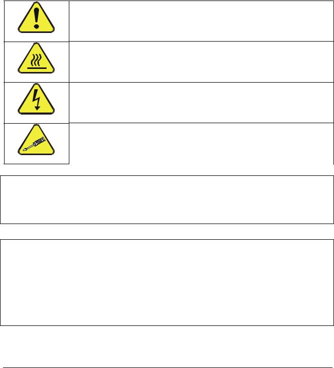
A safety message alerts you to potential hazards that could hurt you or others. Each safety message is associated with a safety alert symbol. These symbols are found in the manual and inside the instrument. The definition of these symbols is described below:
GENERAL SAFETY HAZARD: Refer to the instructions for details on the specific hazard.
CAUTION: Hot Surface Warning.
CAUTION: Electrical Shock Hazard.
TECHNICIAN SYMBOL: All operations marked with this symbol are to be performed by qualified maintenance personnel only.
CAUTION
The analyzer should only be used for the purpose and in the manner described in this manual. If you use the analyzer in a manner other than that for which it was intended, unpredictable behavior could ensue with possible hazardous consequences.
NOTE
Technical Assistance regarding the use and maintenance of the Model 200EH/EM NOx Analyzer or any other Teledyne Instruments product
can be obtained by:
Contacting Teledyne Instruments’ Customer Service Department at 800-324-5190
or
Via the internet at http://www.teledyne-api.com/inquiries.asp
i
04521C (DCN5731)

This page intentionally left blank.
ii
04521C (DCN5731)

Teledyne API - Model 200EH/EM Operation Manual |
Table of Contents |
TABLE OF CONTENTS |
|
1. M200EH/EM Documentation.................................................................................................................................................... |
1 |
1.1. Using This Manual............................................................................................................................................................ |
1 |
2. Specifications, Approvals and Warranty................................................................................................................................... |
3 |
2.1. M200EH/EM Operating Specifications ............................................................................................................................. |
3 |
2.2. CE Mark Compliance ....................................................................................................................................................... |
4 |
2.3. Warranty........................................................................................................................................................................... |
4 |
3. Getting Started ......................................................................................................................................................................... |
7 |
3.1. Unpacking and Initial Setup.............................................................................................................................................. |
7 |
3.1.1. M200EH/EM Layout.................................................................................................................................................. |
8 |
3.1.2. Electrical Connections ............................................................................................................................................ |
10 |
3.1.2.1. Power Connection........................................................................................................................................... |
10 |
3.1.2.2. Analog Output Connections ............................................................................................................................ |
11 |
3.1.2.3. Connecting the Status Outputs ....................................................................................................................... |
12 |
3.1.2.4. Connecting the Control Inputs......................................................................................................................... |
13 |
3.1.2.5. Connecting the Serial Ports ............................................................................................................................ |
14 |
3.1.2.6. Connecting to a LAN or the Internet................................................................................................................ |
14 |
3.1.2.7. Connecting to a Multidrop Network ................................................................................................................. |
14 |
3.1.3. Pneumatic Connections.......................................................................................................................................... |
15 |
3.1.3.1. Calibration Gases ........................................................................................................................................... |
16 |
3.1.3.2. Pneumatic Connections to M200EH/EM Basic Configuration:........................................................................ |
18 |
3.1.3.3. Connections with Internal Valve Options Installed .......................................................................................... |
19 |
3.2. Initial Operation .............................................................................................................................................................. |
20 |
3.2.1. Startup .................................................................................................................................................................... |
20 |
3.2.2. Warm-Up ................................................................................................................................................................ |
22 |
3.2.3. Warning Messages ................................................................................................................................................. |
22 |
3.2.4. Functional Check.................................................................................................................................................... |
24 |
3.3. Calibration ...................................................................................................................................................................... |
25 |
3.3.1. Basic NOx Calibration Procedure............................................................................................................................ |
25 |
3.3.2. Basic O2 Sensor Calibration Procedure.................................................................................................................. |
28 |
3.3.2.1. O2 Calibration Setup ....................................................................................................................................... |
28 |
3.3.2.2. O2 Calibration Method .................................................................................................................................... |
28 |
3.3.3. Interferences for NOX Measurements ..................................................................................................................... |
31 |
4. Frequently Asked Questions & Glossary................................................................................................................................ |
33 |
4.1. Frequently Asked Questions .......................................................................................................................................... |
33 |
4.2. Glossary ......................................................................................................................................................................... |
34 |
5. Optional Hardware and Software ........................................................................................................................................... |
37 |
5.1. External Pumps (OPT 10) .............................................................................................................................................. |
37 |
5.2. Rack Mount Kits (OPTs 20-23)....................................................................................................................................... |
37 |
5.3. Carrying Strap Handle (OPT 29) .................................................................................................................................... |
38 |
5.4. Current Loop Analog Outputs (OPT 41) ......................................................................................................................... |
39 |
5.4.1. Converting Current Loop Analog Outputs to Standard Voltage Outputs................................................................. |
39 |
5.5. Particulate Filter Kit (OPT 42A) ...................................................................................................................................... |
40 |
5.6. Ozone Supply Filter (OPT 49) ........................................................................................................................................ |
40 |
5.7. Calibration Valve Options ............................................................................................................................................... |
40 |
5.7.1. Zero/Span Valves (OPT 50) ................................................................................................................................... |
40 |
5.7.2. Second Range span Valve (OPT 52)...................................................................................................................... |
42 |
5.8. Oxygen Sensor (OPT 65) ............................................................................................................................................... |
45 |
5.8.1. Theory of Operation................................................................................................................................................ |
45 |
5.8.1.1. Paramagnetic measurement of O2 .................................................................................................................. |
45 |
5.8.1.2. Operation Within the M200EH/EM Analyzer ................................................................................................... |
46 |
5.8.1.3. Pneumatic Operation of the O2 Sensor........................................................................................................... |
46 |
5.8.2. Zero Air Scrubber (OPT 64B) ................................................................................................................................. |
48 |
5.8.3. Zero Air Scrubber Maintenance Kit (OPT 43) ......................................................................................................... |
48 |
5.8.4. M200EH/EM Expendables Kit (OPT 42)................................................................................................................. |
48 |
5.8.5. M200EH/EM Spare Parts Kit (OPT 43)................................................................................................................... |
48 |
5.9. Communication Options ................................................................................................................................................. |
48 |
5.9.1. RS232 Modem Cables (OPTs 60 and 60A)............................................................................................................ |
48 |
5.9.2. RS-232 Multidrop (OPT 62) .................................................................................................................................... |
49 |
5.9.3. Ethernet (OPT 63) .................................................................................................................................................. |
49 |
5.10. Sample Gas Conditioners (OPTs 86 & 88)................................................................................................................... |
50 |
|
iii |
04521C (DCN5731)

5.11. Alarm Relay Option (OPT 67)....................................................................................................................................... |
51 |
5.12. Special Software Features ........................................................................................................................................... |
53 |
5.12.1. Maintenance Mode Switch.................................................................................................................................... |
53 |
5.12.2. Second Language Switch ..................................................................................................................................... |
53 |
5.12.3. Dilution Ratio Option............................................................................................................................................. |
53 |
5.13. Additional Manual (OPT 70) ......................................................................................................................................... |
53 |
5.14. Extended Warranty (OPTs 92 & 93)............................................................................................................................. |
54 |
6. Operating Instructions ............................................................................................................................................................ |
55 |
6.1. Overview of Operating Modes ........................................................................................................................................ |
55 |
6.2. Sample Mode ................................................................................................................................................................. |
57 |
6.2.1. Test Functions ........................................................................................................................................................ |
57 |
6.2.2. Warning Messages ................................................................................................................................................. |
59 |
6.3. Calibration Mode ............................................................................................................................................................ |
60 |
6.3.1. Calibration Functions .............................................................................................................................................. |
60 |
6.4. SETUP MODE................................................................................................................................................................ |
61 |
6.5. SETUP CFG: Viewing the Analyzer’s Configuration Information ............................................................................... |
62 |
6.6. SETUP ACAL: Automatic Calibration......................................................................................................................... |
62 |
6.7. SETUP DAS - Using the Data Acquisition System (iDAS) ........................................................................................ |
63 |
6.7.1. iDAS Structure........................................................................................................................................................ |
64 |
6.7.1.1. iDAS Channels................................................................................................................................................ |
64 |
6.7.1.2. iDAS Parameters ............................................................................................................................................ |
65 |
6.7.1.3. iDAS Triggering Events................................................................................................................................... |
65 |
6.7.2. Default iDAS Channels ........................................................................................................................................... |
66 |
6.7.2.1. Viewing iDAS Data and Settings..................................................................................................................... |
68 |
6.7.2.2. Editing iDAS Data Channels ........................................................................................................................... |
69 |
6.7.2.3. Trigger Events................................................................................................................................................. |
70 |
6.7.2.4. Editing iDAS Parameters ................................................................................................................................ |
71 |
6.7.2.5. Sample Period and Report Period .................................................................................................................. |
73 |
6.7.2.6. Number of Records......................................................................................................................................... |
75 |
6.7.2.7. RS-232 Report Function ................................................................................................................................. |
76 |
6.7.2.8. Compact Report.............................................................................................................................................. |
76 |
6.7.2.9. Starting Date................................................................................................................................................... |
76 |
6.7.2.10. Disabling/Enabling Data Channels................................................................................................................ |
77 |
6.7.2.11. HOLDOFF Feature ....................................................................................................................................... |
77 |
6.7.3. Remote iDAS Configuration.................................................................................................................................... |
78 |
6.8. SETUP RNGE: Range Units and Dilution Configuration............................................................................................ |
80 |
6.8.1. Range Units............................................................................................................................................................ |
80 |
6.8.2. Dilution Ratio .......................................................................................................................................................... |
81 |
6.9. SETUP PASS: Password Feature ............................................................................................................................. |
82 |
6.10. SETUP CLK: Setting the Internal Time-of-Day Clock .............................................................................................. |
84 |
6.11. SETUP MORE COMM: Setting Up the Analyser’s Communication Ports ........................................................... |
86 |
6.11.1. Analyzer ID ........................................................................................................................................................... |
86 |
6.11.2. COM Port Default Settings ................................................................................................................................... |
87 |
6.11.3. RS-232 COM Port Cable Connections ................................................................................................................. |
87 |
6.11.4. RS-485 Configuration of COM2............................................................................................................................ |
89 |
6.11.5. DTE and DCE Communication ............................................................................................................................. |
90 |
6.11.6. Ethernet Card Configuration ................................................................................................................................. |
91 |
6.11.6.1. Ethernet Card COM2 Communication Modes and Baud Rate...................................................................... |
91 |
6.11.6.2. Configuring the Ethernet Interface Option using DHCP ................................................................................ |
91 |
6.11.6.3. Manually Configuring the Network IP Addresses .......................................................................................... |
94 |
6.11.6.4. Changing the Analyzer’s HOSTNAME.......................................................................................................... |
96 |
6.11.7. Multidrop RS-232 Set Up...................................................................................................................................... |
97 |
6.11.8. COM Port Communication Modes ........................................................................................................................ |
99 |
6.11.9. COM Port Baud Rate.......................................................................................................................................... |
101 |
6.11.10. COM Port Testing ............................................................................................................................................. |
102 |
6.12. SETUP MORE VARS: Internal Variables (VARS) ............................................................................................. |
103 |
6.12.1. Setting the Gas Measurement Mode .................................................................................................................. |
105 |
6.13. SETUP MORE DIAG: Diagnostics MENU ........................................................................................................ |
106 |
6.13.1. Accessing the Diagnostic Features..................................................................................................................... |
107 |
6.13.2. Signal I/O............................................................................................................................................................ |
108 |
6.13.3. Analog Output Step Test .................................................................................................................................... |
109 |
6.13.4. ANALOG OUTPUTS and Reporting Ranges...................................................................................................... |
110 |
6.13.4.1. Analog Output Signals Available on the M200EH/EM................................................................................. |
110 |
6.13.4.2. Physical Range versus Analog Output Reporting Ranges.......................................................................... |
111 |
6.13.5. ANALOG I/O CONFIGURATION........................................................................................................................ |
113 |
iv |
|
|
04521C (DCN5731) |

Teledyne API - Model 200EH/EM Operation Manual |
Table of Contents |
6.13.5.1. The Analog I/O Configuration Submenu. .................................................................................................... |
113 |
6.13.5.2. Analog Output Signal Type and Range Selection....................................................................................... |
115 |
6.13.5.3. Turning the Analog Output Over-Range Feature ON/OFF.......................................................................... |
116 |
6.13.5.4. Adding a Recorder Offset to an Analog Output........................................................................................... |
117 |
6.13.5.5. Assigning an iDAS parameter to an Analog Output Channel...................................................................... |
118 |
Reporting Gas Concentrations via the M200EH/EM Analog Output Channels ........................................ |
118 |
6.13.5.6. Setting the Reporting Range Scale for an Analog Output........................................................................... |
121 |
6.13.5.7. Setting Data Update Rate for an Analog Output ......................................................................................... |
123 |
6.13.5.8. Turning an Analog Output On or Off ........................................................................................................... |
124 |
6.13.6. ANALOG OUTPUT CALIBRATION .................................................................................................................... |
125 |
6.13.6.1. Automatic Analog Output Calibration .......................................................................................................... |
126 |
6.13.6.2. Manual Calibration of Analog Output configured for Voltage Ranges......................................................... |
127 |
6.13.6.3. Manual Calibration of Analog Outputs configured for Current Loop Ranges .............................................. |
128 |
6.13.6.4. AIN Calibration............................................................................................................................................ |
131 |
6.13.7. OTHER DIAG MENU FUNCTIONS .................................................................................................................... |
132 |
6.13.7.1. Display Sequence Configuration................................................................................................................. |
132 |
6.13.7.2. Optic Test ................................................................................................................................................... |
135 |
6.13.7.3. Electrical Test ............................................................................................................................................. |
136 |
6.13.7.4. Ozone Generator Override ......................................................................................................................... |
137 |
6.13.7.5. Flow Calibration .......................................................................................................................................... |
138 |
6.14. SETUP – ALRM: Using the optional Gas Concentration Alarms (OPT 67) ................................................................ |
139 |
6.15. REMOTE OPERATION OF THE ANALYZER ............................................................................................................ |
140 |
6.15.1. Remote Operation Using the External Digital I/O ............................................................................................... |
140 |
6.15.1.1. Status Outputs ............................................................................................................................................ |
140 |
6.15.1.2. Control Inputs.............................................................................................................................................. |
141 |
6.15.2. Remote Operation Using the External Serial I/O ................................................................................................ |
142 |
6.15.2.1. Terminal Operating Modes ......................................................................................................................... |
142 |
6.15.2.2. Help Commands in Terminal Mode............................................................................................................. |
143 |
6.15.2.3. Command Syntax ....................................................................................................................................... |
143 |
6.15.2.4. Data Types.................................................................................................................................................. |
144 |
6.15.2.5. Status Reporting ......................................................................................................................................... |
145 |
6.15.2.6. Remote Access by Modem ......................................................................................................................... |
145 |
6.15.2.7. COM Port Password Security ..................................................................................................................... |
147 |
6.15.2.8. APICOM Remote Control Program ............................................................................................................. |
148 |
6.15.3. Additional Communications Documentation ....................................................................................................... |
148 |
6.15.4. Using the M200EH/EM with a Hessen Protocol Network.................................................................................... |
149 |
6.15.4.1. General Overview of Hessen Protocol ........................................................................................................ |
149 |
6.15.4.2. Hessen COMM Port Configuration.............................................................................................................. |
149 |
6.15.4.3. Selecting a Hessen Protocol Type .............................................................................................................. |
150 |
6.15.4.4. Setting The Hessen Protocol Response Mode ........................................................................................... |
151 |
6.15.4.5. Hessen Protocol Gas ID ............................................................................................................................. |
152 |
6.15.4.6. Setting Hessen Protocol Status Flags......................................................................................................... |
153 |
6.15.4.7. Instrument ID Code..................................................................................................................................... |
154 |
7. Calibration Procedures......................................................................................................................................................... |
155 |
7.1. Calibration Preparations ............................................................................................................................................... |
155 |
7.1.1. Required Equipment, Supplies, and Expendables................................................................................................ |
155 |
7.1.2. Zero Air................................................................................................................................................................. |
155 |
7.1.3. Span Calibration Gas Standards & Traceability.................................................................................................... |
156 |
7.1.3.1. Traceability ................................................................................................................................................... |
156 |
7.1.4. Data Recording Devices ....................................................................................................................................... |
157 |
7.1.5. NO2 Conversion Efficiency ................................................................................................................................... |
157 |
7.1.5.1. Determining / Updating the NO2 Converter Efficiency................................................................................... |
157 |
7.2. Manual Calibration ....................................................................................................................................................... |
160 |
7.3. Calibration Checks ....................................................................................................................................................... |
163 |
7.4. Manual Calibration with Zero/Span Valves................................................................................................................... |
164 |
7.5. Calibration Checks with Zero/Span Valves................................................................................................................... |
167 |
7.6. Calibration With Remote Contact Closures .................................................................................................................. |
168 |
7.7. Automatic Calibration (AutoCal) ................................................................................................................................... |
169 |
7.8. Calibration Quality Analysis.......................................................................................................................................... |
172 |
8. EPA Protocol Calibration...................................................................................................................................................... |
173 |
9. Instrument Maintenance....................................................................................................................................................... |
175 |
9.1. Maintenance Schedule................................................................................................................................................. |
175 |
9.2. Predictive Diagnostics .................................................................................................................................................. |
177 |
9.3. Maintenance Procedures.............................................................................................................................................. |
177 |
9.3.1. Changing the Sample Particulate Filter ................................................................................................................ |
178 |
|
v |
04521C (DCN5731)

9.3.2. Changing the O3 Dryer Particulate Filter............................................................................................................... |
179 |
9.3.3. Maintaining the External Sample Pump................................................................................................................ |
180 |
9.3.3.1. Rebuilding the Pump..................................................................................................................................... |
180 |
9.3.3.2. Changing the Inline Exhaust Scrubber.......................................................................................................... |
180 |
9.3.4. Changing the Pump and IZS Dust Filters ............................................................................................................. |
180 |
9.3.5. Changing the External Zero Air Scrubber ............................................................................................................. |
182 |
9.3.6. Changing the NO2 converter................................................................................................................................. |
183 |
9.3.7. Cleaning the Reaction Cell ................................................................................................................................... |
184 |
9.3.8. Changing Critical Flow Orifices............................................................................................................................. |
185 |
9.3.9. Checking for Light Leaks ...................................................................................................................................... |
186 |
10. Theory of Operation ........................................................................................................................................................... |
189 |
10.1. Measurement Principle............................................................................................................................................... |
189 |
10.1.1. Chemiluminescence ........................................................................................................................................... |
189 |
10.1.2. NOX and NO2 Determination ............................................................................................................................... |
190 |
10.2. Chemiluminescence Detection ................................................................................................................................... |
191 |
10.2.1. The Photo Multiplier Tube................................................................................................................................... |
191 |
10.2.2. Optical Filter ....................................................................................................................................................... |
192 |
10.2.3. Auto Zero............................................................................................................................................................ |
192 |
10.2.4. Measurement Interferences................................................................................................................................ |
193 |
10.2.4.1. Direct Interference ...................................................................................................................................... |
193 |
10.2.4.2. Third Body Quenching ................................................................................................................................ |
193 |
10.2.4.3. Light Leaks.................................................................................................................................................. |
194 |
10.3. Pneumatic Operation.................................................................................................................................................. |
195 |
10.3.1. Pump and Exhaust Manifold............................................................................................................................... |
195 |
10.3.2. Sample Gas Flow ............................................................................................................................................... |
196 |
10.3.2.1. NO/NOx and AutoZero cycles ..................................................................................................................... |
196 |
10.3.3. Flow Rate Control - Critical Flow Orifices ........................................................................................................... |
197 |
10.3.3.1. Critical Flow Orifice ..................................................................................................................................... |
199 |
10.3.4. Sample Particulate Filter..................................................................................................................................... |
201 |
10.3.5. Ozone Gas Air Flow............................................................................................................................................ |
201 |
10.3.6. O3 Generator...................................................................................................................................................... |
202 |
10.3.7. Perma Pure® Dryer ............................................................................................................................................. |
203 |
10.3.8. Ozone Supply Air Filter....................................................................................................................................... |
205 |
10.3.9. Ozone Scrubber ................................................................................................................................................. |
205 |
10.3.10. Pneumatic Sensors........................................................................................................................................... |
206 |
10.3.10.1. Vacuum Manifold ...................................................................................................................................... |
206 |
10.3.10.2. Sample Pressure Sensor .......................................................................................................................... |
206 |
10.3.10.3. Vacuum Pressure Sensor ......................................................................................................................... |
207 |
10.3.10.4. O3 Supply Air Flow Sensor........................................................................................................................ |
207 |
10.3.11. Dilution Manifold ............................................................................................................................................... |
207 |
10.4. Electronic Operation................................................................................................................................................... |
209 |
10.4.1. CPU .................................................................................................................................................................... |
210 |
10.4.1.1. Disk On Chip............................................................................................................................................... |
211 |
10.4.1.2. Flash Chip................................................................................................................................................... |
211 |
10.4.2. Sensor Module, Reaction Cell ............................................................................................................................ |
211 |
10.4.2.1. Reaction Cell Heating Circuit ...................................................................................................................... |
211 |
10.4.3. Photo Multiplier Tube (PMT)............................................................................................................................... |
212 |
10.4.4. PMT Cooling System. ......................................................................................................................................... |
213 |
10.4.4.1. TEC Control Board...................................................................................................................................... |
213 |
10.4.5. PMT Preamplifier ................................................................................................................................................ |
214 |
10.4.6. Pneumatic Sensor Board.................................................................................................................................... |
215 |
10.4.7. Relay Board........................................................................................................................................................ |
215 |
10.4.7.1. Relay PCA Location and Layout ................................................................................................................. |
215 |
10.4.7.2. Heater Control............................................................................................................................................. |
215 |
10.4.7.3. Thermocouple Inputs and Configuration Jumper (JP5)............................................................................... |
216 |
10.4.7.4. Valve Control .............................................................................................................................................. |
217 |
10.4.8. Status LEDs & Watch Dog Circuitry.................................................................................................................... |
218 |
10.4.8.1. Watchdog Indicator (D1) ............................................................................................................................. |
218 |
10.4.9. Motherboard ....................................................................................................................................................... |
219 |
10.4.9.1. A to D Conversion....................................................................................................................................... |
219 |
10.4.9.2. Sensor Inputs.............................................................................................................................................. |
219 |
10.4.9.3. Thermistor Interface.................................................................................................................................... |
220 |
10.4.10. Analog Outputs................................................................................................................................................. |
220 |
10.4.11. External Digital I/O............................................................................................................................................ |
221 |
10.4.12. I2C Data Bus ..................................................................................................................................................... |
221 |
vi |
|
|
04521C (DCN5731) |

Teledyne API - Model 200EH/EM Operation Manual |
Table of Contents |
10.4.13. Power-up Circuit ............................................................................................................................................... |
221 |
10.5. Power Distribution &Circuit Breaker ........................................................................................................................... |
222 |
10.6. Communications Interface.......................................................................................................................................... |
223 |
10.6.1. Front Panel Interface .......................................................................................................................................... |
224 |
10.6.1.1. Analyzer Status LED’s ................................................................................................................................ |
224 |
10.6.1.2. Keyboard .................................................................................................................................................... |
224 |
10.6.1.3. Display ........................................................................................................................................................ |
225 |
10.6.1.4. Keyboard/Display Interface Electronics ...................................................................................................... |
225 |
10.7. Software Operation .................................................................................................................................................... |
227 |
10.7.1. Adaptive Filter..................................................................................................................................................... |
228 |
10.7.2. Calibration - Slope and Offset............................................................................................................................. |
228 |
10.7.3. Temperature/Pressure Compensation (TPC) ..................................................................................................... |
229 |
10.7.4. NO2 Converter Efficiency Compensation............................................................................................................ |
230 |
10.7.5. Internal Data Acquisition System (iDAS) ............................................................................................................ |
230 |
11. Troubleshooting & Repair .................................................................................................................................................. |
231 |
11.1. General Troubleshooting ............................................................................................................................................ |
231 |
11.1.1. Warning Messages ............................................................................................................................................. |
232 |
11.1.2. Fault Diagnosis with Test Functions ................................................................................................................... |
232 |
11.1.3. Using the Diagnostic Signal I/O Function ........................................................................................................... |
233 |
11.1.4. Status LED’s....................................................................................................................................................... |
235 |
11.1.4.1. Motherboard Status Indicator (Watchdog) .................................................................................................. |
235 |
11.1.4.2. CPU Status Indicator .................................................................................................................................. |
235 |
11.1.4.3. Relay Board and Status LEDs .................................................................................................................... |
235 |
11.2. Gas Flow Problems .................................................................................................................................................... |
238 |
11.2.1. M200EH Internal Gas Flow Diagrams ................................................................................................................ |
238 |
11.2.2. M200EM Internal Gas Flow Diagrams ................................................................................................................ |
241 |
11.2.3. Zero or Low Flow Problems................................................................................................................................ |
243 |
11.2.3.1. Sample Flow is Zero or Low........................................................................................................................ |
243 |
11.2.3.2. Ozone Flow is Zero or Low ......................................................................................................................... |
244 |
11.2.4. High Flow............................................................................................................................................................ |
245 |
11.2.5. Sample Flow is Zero or Low But Analyzer Reports Correct Flow ....................................................................... |
245 |
11.3. Calibration Problems .................................................................................................................................................. |
246 |
11.3.1. Negative Concentrations .................................................................................................................................... |
246 |
11.3.2. No Response...................................................................................................................................................... |
246 |
11.3.3. Unstable Zero and Span..................................................................................................................................... |
247 |
11.3.4. Inability to Span - No SPAN Key ........................................................................................................................ |
247 |
11.3.5. Inability to Zero - No ZERO Key ......................................................................................................................... |
248 |
11.3.6. Non-Linear Response......................................................................................................................................... |
248 |
11.3.7. Discrepancy Between Analog Output and Display ............................................................................................. |
249 |
11.3.8. Discrepancy between NO and NOX slopes......................................................................................................... |
249 |
11.4. Other Performance Problems..................................................................................................................................... |
249 |
11.4.1. Excessive noise.................................................................................................................................................. |
249 |
11.4.2. Slow Response................................................................................................................................................... |
249 |
11.4.3. Auto-zero Warnings ............................................................................................................................................ |
250 |
11.5. Subsystem Checkout.................................................................................................................................................. |
251 |
11.5.1. Simple Vacuum Leak and Pump Check ............................................................................................................. |
251 |
11.5.2. Detailed Pressure Leak Check ........................................................................................................................... |
251 |
11.5.3. Performing a Sample Flow Check ...................................................................................................................... |
252 |
11.5.4. AC Power Configuration ..................................................................................................................................... |
253 |
11.5.4.1. AC configuration – Internal Pump (JP7)...................................................................................................... |
254 |
11.5.4.2. AC Configuration – Standard Heaters (JP2) ............................................................................................... |
255 |
11.5.4.3. AC Configuration –Heaters for Option Packages (JP6) .............................................................................. |
256 |
11.5.5. DC Power Supply Test Points ............................................................................................................................ |
257 |
11.5.6. I2C Bus ............................................................................................................................................................... |
257 |
11.5.7. Keyboard / Display Interface............................................................................................................................... |
258 |
11.5.8. Genreal Relay Board Diagnostic ........................................................................................................................ |
258 |
11.5.9. Motherboard ....................................................................................................................................................... |
259 |
11.5.9.1. A/D functions............................................................................................................................................... |
259 |
11.5.9.2. Analog Output Voltages .............................................................................................................................. |
259 |
11.5.9.3. Status Outputs ............................................................................................................................................ |
260 |
11.5.9.4. Control Inputs.............................................................................................................................................. |
261 |
11.5.10. CPU .................................................................................................................................................................. |
261 |
11.5.11. RS-232 Communication.................................................................................................................................... |
262 |
11.5.11.1. General RS-232 Troubleshooting ............................................................................................................. |
262 |
11.5.11.2. Modem or Terminal Operation .................................................................................................................. |
262 |
|
vii |
04521C (DCN5731)

11.5.12. PMT Sensor...................................................................................................................................................... |
263 |
|
11.5.13. PMT Preamplifier Board ................................................................................................................................... |
263 |
|
11.5.14. High Voltage Power Supply .............................................................................................................................. |
263 |
|
11.5.15. Pneumatic Sensor Assembly............................................................................................................................ |
264 |
|
11.5.15.1. Reaction Cell Pressure ............................................................................................................................. |
264 |
|
11.5.15.2. Sample Pressure ...................................................................................................................................... |
264 |
|
11.5.15.3. Ozone Flow............................................................................................................................................... |
265 |
|
11.5.16. NO2 Converter .................................................................................................................................................. |
265 |
|
11.5.17. O3 Generator .................................................................................................................................................... |
266 |
|
11.5.18. Box Temperature.............................................................................................................................................. |
266 |
|
11.5.19. PMT Temperature............................................................................................................................................. |
266 |
|
11.6. Repair Procedures ..................................................................................................................................................... |
267 |
|
11.6.1. Disk-on-Chip Replacement................................................................................................................................. |
267 |
|
11.6.2. Flash Chip Replacement or Upgrade.................................................................................................................. |
268 |
|
11.6.3. O3 Generator Replacement ................................................................................................................................ |
268 |
|
11.6.4. Sample and Ozone Dryer Replacement ............................................................................................................. |
269 |
|
11.6.5. PMT Sensor Hardware Calibration ..................................................................................................................... |
270 |
|
11.6.6. Replacing the PMT, HVPS or TEC ..................................................................................................................... |
271 |
|
11.7. Removing / Replacing the Relay PCA from the Instrument ........................................................................................ |
274 |
|
11.8. Technical Assistance.................................................................................................................................................. |
275 |
|
12. A Primer on Electro-Static Discharge................................................................................................................................. |
277 |
|
12.1. How Static Charges are Created................................................................................................................................ |
277 |
|
12.2. How Electro-Static Charges Cause Damage.............................................................................................................. |
278 |
|
12.3. Common Myths About ESD Damage ......................................................................................................................... |
279 |
|
12.4. Basic Principles of Static Control................................................................................................................................ |
279 |
|
12.4.1. General Rules..................................................................................................................................................... |
280 |
|
12.4.2. Basic anti-ESD Procedures for Analyzer Repair and Maintenance .................................................................... |
281 |
|
12.4.2.1. Working at the Instrument Rack.................................................................................................................. |
281 |
|
12.4.2.2. Working at an Anti-ESD Work Bench.......................................................................................................... |
281 |
|
12.4.2.3. Transferring Components from Rack to Bench and Back ........................................................................... |
282 |
|
12.4.2.4. Opening Shipments from Teledyne Instruments Customer Service............................................................ |
282 |
|
12.4.2.5. Packing Components for Return to Teledyne Instruments Customer Service. ........................................... |
283 |
|
LIST OF FIGURES |
|
|
Figure 3-1: |
M200EH/EM Layout....................................................................................................................... |
8 |
Figure 3-2: |
M200EH/EM Rear Panel Layout.................................................................................................... |
9 |
Figure 3-3: |
M200EH/EM Front Panel Layout ................................................................................................... |
9 |
Figure 3-4: |
Analog Output Connector ............................................................................................................ |
11 |
Figure 3-5: |
Status Output Connector ............................................................................................................. |
12 |
Figure 3-6: |
Control Input Connector............................................................................................................... |
13 |
Figure 3-7: |
M200EH Internal Pneumatic Block Diagram - Standard Configuration....................................... |
15 |
Figure 3-8: |
M200EM Internal Pneumatic Block Diagram - Standard Configuration ...................................... |
16 |
Figure 3-9: |
Pneumatic Connections–Basic Configuration–Using Gas Dilution Calibrator............................. |
18 |
Figure 3-10: |
Pneumatic Connections–Basic Configuration–Using Bottled Span Gas..................................... |
18 |
Figure 3-11: |
Pneumatic Connections–With Zero/Span Valve Option (50) ...................................................... |
19 |
Figure 3-12: |
Pneumatic Connections–With 2-Span point Option (52) –Using Bottled Span Gas ................... |
20 |
Figure 3-13: |
Front Panel Display During Startup Sequence............................................................................ |
21 |
Figure 3-14: |
O2 Sensor Calibration Set Up ...................................................................................................... |
28 |
Figure 5-1: |
M200EH/EM with Carrying Strap Handle and Rack Mount Brackets.......................................... |
38 |
Figure 5-2: |
Current Loop Option Installed on the Motherboard ..................................................................... |
39 |
Figure 5-3: |
M200EH – Internal Pneumatics with Zero-Span Valve Option 50............................................... |
41 |
Figure 5-4: |
M200EM – Internal Pneumatics with Zero-Span Valve Option 50 .............................................. |
41 |
Figure 5-5: |
M200EH – Internal Pneumatics with Second Span Point Valve Option 52................................. |
44 |
Figure 5-6: |
M200EM – Internal Pneumatics with Second Span Point Valve Option 52 ................................ |
45 |
Figure 5-7: |
Oxygen Sensor - Principle of Operation ...................................................................................... |
46 |
Figure 5-8: |
M200EH – Internal Pneumatics with O2 Sensor Option 65 ......................................................... |
47 |
Figure 5-9: |
M200EM – Internal Pneumatics with O2 Sensor Option 65......................................................... |
47 |
Figure 5-10: |
M200EH/EM Multidrop Card........................................................................................................ |
49 |
viii |
|
|
|
04521C (DCN5731) |
|
Teledyne API - Model 200EH/EM Operation Manual |
List of Figures |
|
|||
Figure 5-11: |
M200EH/EM Ethernet Card ......................................................................................................... |
|
50 |
||
Figure 5-12: |
M200EH/EM Rear Panel with Ethernet Installed......................................................................... |
50 |
|||
Figure 5-13: |
Alarm Relay Output Pin Assignments.......................................................................................... |
|
52 |
||
Figure 6-6-1: |
Front Panel Display...................................................................................................................... |
|
55 |
||
Figure 6-6-2: |
Viewing M200EH/EM TEST Functions........................................................................................ |
|
58 |
||
Figure 6-6-3: |
Viewing and Clearing M200EH/EM WARNING Messages ......................................................... |
59 |
|||
Figure 6-6-4: |
APICOM Graphical User Interface for Configuring the iDAS ...................................................... |
78 |
|||
Figure 6-6-5: |
iDAS Configuration Through a Terminal Emulation Program...................................................... |
79 |
|||
Figure 6-6-6: |
Back Panel connector Pin-Outs for COM1 & COM2 in RS-232 mode........................................ |
87 |
|||
Figure 6-6-7: |
CPU connector Pin-Outs for COM1 & COM2 in RS-232 mode................................................... |
88 |
|||
Figure 6-6-8: |
CPU card Locations of RS-232/486 Switches, Connectors and Jumpers................................... |
89 |
|||
Figure 6-6-9: |
Back Panel connector Pin-Outs for COM2 in RS-485 mode....................................................... |
90 |
|||
Figure 6-6-10: |
CPU connector Pin-Outs for COM2 in RS-485 mode.................................................................. |
90 |
|||
Figure 6-6-11: |
Location of JP2 on RS232-Multidrop PCA |
(option 62) ............................................................... |
97 |
||
Figure 6-6-12: |
RS232-Multidrop PCA Host/Analyzer Interconnect Diagram ...................................................... |
98 |
|||
Figure 6-6-13: |
Analog Output Connector Key .................................................................................................. |
|
110 |
||
Figure 6-6-14: |
Setup for Calibrating Analog Outputs ....................................................................................... |
|
127 |
||
Figure 6-6-15: |
Setup for Calibrating Current Outputs ...................................................................................... |
|
129 |
||
Figure 6-6-16: |
Alternative Setup for Calibrating Current Outputs .................................................................... |
129 |
|||
Figure 6-6-17: |
Status Output ConnectorTable 6-29: Status Output Pin Assignments..................................... |
140 |
|||
Table 6-29: |
Status Output Pin Assignments ................................................................................................ |
|
141 |
||
Figure 6-6-18: |
Control Inputs with local 5 V power supply............................................................................... |
|
142 |
||
Figure 6-6-19: |
Control Inputs with external 5 V power supply ......................................................................... |
142 |
|||
Figure 6-6-20: |
APICOM Remote Control Program Interface ........................................................................... |
148 |
|||
Figure 7-1: |
Gas Supply Setup for Determination of NO2 Conversion Efficiency......................................... |
157 |
|||
Figure 7-2: |
Pneumatic Connections–With Zero/Span Valve Option (50) ................................................... |
160 |
|||
Figure 7-3: |
Pneumatic Connections–With 2-Span point Option (52) –Using Bottled Span Gas ................ |
160 |
|||
Figure7-4: |
Pneumatic Connections–With Zero/Span Valve Option (50) ................................................... |
164 |
|||
Figure 9-1: |
Sample Particulate Filter Assembly.......................................................................................... |
|
178 |
||
Figure |
9-2: |
Particle Filter on O3 Supply Air Dryer ....................................................................................... |
|
179 |
|
Figure 9-3: |
Zero Air Scrubber Assembly..................................................................................................... |
|
182 |
||
Figure 9-4: |
NO2 Converter Assembly.......................................................................................................... |
|
183 |
||
Figure |
9-5: |
Reaction Cell Assembly............................................................................................................ |
|
184 |
|
Figure |
9-6: |
Critical Flow Orifice Assembly .................................................................................................. |
|
186 |
|
Figure 10-10-1: |
M200EH/EM Sensitivity Spectrum............................................................................................ |
|
190 |
||
Figure 10-10-2: |
NO2 Conversion Principle ......................................................................................................... |
|
191 |
||
Figure 10-10-3: |
Reaction Cell with PMT Tube ................................................................................................... |
|
192 |
||
Figure 10-10-4: |
Reaction Cell During the AutoZero Cycle................................................................................. |
|
193 |
||
Figure 10-10-5: |
External Pump Pack ................................................................................................................. |
|
195 |
||
Figure 10-10-6: |
Location of Gas Flow Control Assemblies for M200EH............................................................ |
197 |
|||
Figure 10-10-7: |
Location of Gas Flow Control Assemblies for M200EM ........................................................... |
198 |
|||
Figure 10-10-8: |
Location of Gas Flow Control Assemblies for M200EH with O2 sensor Option 65 .................. |
198 |
|||
Figure 10-10-9: |
Location of Gas Flow Control Assemblies for M200EH with Second Span Point Option 52 ... |
199 |
|||
Figure 10-10-10: |
Flow Control Assembly & Critical Flow Orifice ......................................................................... |
200 |
|||
Figure 10-10-11: |
Ozone Generator Principle ....................................................................................................... |
|
202 |
||
Figure 10-10-12: |
Semi-Permeable Membrane Drying Process ........................................................................... |
203 |
|||
Figure 10-10-13: |
M200EH/EM Perma Pure® Dryer.............................................................................................. |
|
204 |
||
Figure 10-10-14: |
Vacuum Manifold ...................................................................................................................... |
|
206 |
||
Figure 10-10-15: |
Dilution Manifold ....................................................................................................................... |
|
208 |
||
Figure 10-10-16: |
M200EH/EM Electronic Block Diagram .................................................................................... |
|
209 |
||
Figure 10-10-17: |
M200EH/EM CPU Board Annotated......................................................................................... |
|
210 |
||
Figure 10-10-18: |
PMT Housing Assembly ........................................................................................................... |
|
212 |
||
Figure 10-10-19: |
Basic PMT Design .................................................................................................................... |
|
212 |
||
Figure 10-10-20: |
PMT Cooling System ................................................................................................................ |
|
213 |
||
Figure 10-10-21: |
PMT Preamp Block Diagram .................................................................................................... |
|
214 |
||
Figure 10-10-22: |
Heater Control Loop Block Diagram......................................................................................... |
|
215 |
||
Figure 10-10-23: |
Thermocouple Configuration Jumper (JP5) Pin-Outs............................................................... |
216 |
|||
Figure 10-10-24: |
Status LED Locations – Relay PCA......................................................................................... |
|
218 |
||
ix
04521C (DCN5731)

Figure 10-10-25: Power Distribution Block Diagram ........................................................................................... |
222 |
|
Figure 10-10-26: Interface Block Diagram ........................................................................................................... |
223 |
|
Figure 10-10-27: M200EH/EM Front Panel Layout .............................................................................................. |
224 |
|
Figure 10-10-28: Keyboard and Display Interface Block Diagram ....................................................................... |
225 |
|
Figure 10-10-29: Schematic of Basic Software Operation ................................................................................... |
227 |
|
Figure 11-1: |
Viewing and Clearing Warning Messages................................................................................ |
232 |
Figure 11-2: |
Switching Signal I/O Functions ................................................................................................. |
234 |
Figure 11-3: |
Motherboard Watchdog Status Indicator .................................................................................. |
235 |
Figure 11-4: |
Relay Board PCA...................................................................................................................... |
236 |
Figure 11-5: |
M200EH – Basic Internal Gas Flow.......................................................................................... |
238 |
Figure 11-6: |
M200EH – Internal Gas Flow With OPT 50.............................................................................. |
239 |
Figure 11-7: |
M200EH – Internal Gas Flow With OPT 52.............................................................................. |
239 |
Figure 11-8: |
M200EH – Internal Gas Flow With OPT 65.............................................................................. |
240 |
Figure 11-9: |
M200EH – Internal Gas Flow With OPT 50 + OPT 65 ............................................................. |
240 |
Figure 11-10: |
M200EM – Basic Internal Gas Flow ......................................................................................... |
241 |
Figure 11-11: |
M200EM – Internal Gas Flow With OPT 50 ............................................................................. |
241 |
Figure 11-12: |
M200EM – Internal Gas Flow With OPT 52 ............................................................................. |
242 |
Figure 11-13: |
M200EM – Internal Gas Flow With OPT 65 ............................................................................. |
242 |
Figure 11-14: |
M200EM – Internal Gas Flow With OPT 50 + OPT 65............................................................. |
243 |
Figure 11-15: |
Location of AC power Configuration Jumpers .......................................................................... |
253 |
Figure 11-16: |
Pump AC Power Jumpers (JP7)............................................................................................... |
254 |
Figure 11-17: |
Typical Set Up of AC Heater Jumper Set (JP2) ....................................................................... |
255 |
Figure 11-18: |
Typical Set Up of AC Heater Jumper Set (JP2) ....................................................................... |
256 |
Figure 11-19: |
Typical Set Up of Status Output Test ....................................................................................... |
260 |
Figure 11-20: |
Pressure / Flow Sensor Assembly............................................................................................ |
264 |
Figure 11-22: |
Pre-Amplifier Board Layout....................................................................................................... |
270 |
Figure 11-22: |
M200EH/EM Sensor Assembly ................................................................................................ |
272 |
Figure 11-23: |
Relay PCA with AC Relay Retainer In Place............................................................................ |
274 |
Figure 11-24: |
Relay PCA Mounting Screw Locations.................................................................................... |
274 |
Figure 12-1: Triboelectric Charging....................................................................................................................... |
277 |
|
Figure 12-2: Basic anti-ESD Work Station ............................................................................................................ |
280 |
|
LIST OF TABLES |
|
|
|
Table 2-1: |
Model 200EH/EM Basic Unit Specifications .................................................................................. |
|
3 |
Table 3-1: |
Analog Output Data Type Default Settings.................................................................................. |
|
11 |
Table 3-2: |
Analog Output Pin-Outs............................................................................................................... |
|
11 |
Table 3-3: |
Status Output Signals .................................................................................................................. |
|
12 |
Table 3-4: |
Control Input Signals ................................................................................................................... |
|
13 |
Table 3-5: |
Inlet / Outlet Connector Nomenclature ........................................................................................ |
|
15 |
Table 3-6: |
NIST-SRM's Available for Traceability of NOx |
Calibration Gases |
................................................17 |
Table 3-7: |
Front Panel Display During System Warm-Up ............................................................................ |
22 |
|
Table 3-8: |
Possible Warning Messages at Start-Up..................................................................................... |
|
23 |
Table 5-1: |
Zero/Span Valve States............................................................................................................... |
|
42 |
Table 5-2: |
Two-Point Span Valve Operating States ..................................................................................... |
|
43 |
Table 5-3: |
Contents of Zero Air Scrubber Maintenance Kit .......................................................................... |
48 |
|
Table 5-4: |
Dryer and NH3 Removal Options................................................................................................. |
|
51 |
Table 5-5: |
Alarm Relay Output Assignments................................................................................................ |
|
51 |
Table 5-6 |
Concentration Alarm Relay Output Operation ............................................................................. |
|
52 |
Table 6-1: |
Analyzer Operating modes .......................................................................................................... |
|
56 |
Table 6-2: |
Test Functions Defined................................................................................................................ |
|
57 |
Table 6-3: |
List of Warning Messages Revision F.0 ...................................................................................... |
|
59 |
Table 6-4: |
Primary Setup Mode Features and Functions ............................................................................. |
|
61 |
Table 6-5: |
Secondary Setup Mode Features and Functions ........................................................................ |
61 |
|
x |
|
|
|
|
|
|
04521C (DCN5731) |

Teledyne API - Model 200EH/EM Operation Manual |
List of Tables |
|
Table 6-6: |
Front Panel LED Status Indicators for iDAS................................................................................ |
63 |
Table 6-7: |
iDAS Data Channel Properties .................................................................................................... |
64 |
Table 6-8: |
iDAS Data Parameter Functions.................................................................................................. |
65 |
Table 6-9: |
M200EH/EM Default iDAS Configuration .................................................................................... |
67 |
Table 6-10: |
Password Levels.......................................................................................................................... |
82 |
Table 6-11: |
Ethernet Status Indicators ........................................................................................................... |
91 |
Table 6-12: |
LAN/Internet Configuration Properties......................................................................................... |
92 |
Table 6-13: |
Internet Configuration Keypad Functions .................................................................................... |
96 |
Table 6-14: |
COMM Port Communication modes ............................................................................................ |
99 |
Table 6-15: |
Variable Names (VARS) ........................................................................................................... |
103 |
Table 6-16: |
M200EH/EM Diagnostic (DIAG) Functions............................................................................... |
106 |
Table 6-17: |
Analog Output Voltage Ranges with Over-Range Active ......................................................... |
110 |
Table 6-18: |
Analog Output Pin Assignments ............................................................................................... |
110 |
Table 6-19: |
Analog Output Current Loop Range ......................................................................................... |
111 |
Table 6-20: |
Example of Analog Output configuration for M200EH/EM ....................................................... |
111 |
Table 6-21: |
DIAG - Analog I/O Functions .................................................................................................... |
113 |
Table 6-22: |
Analog Output Data Type Default Settings............................................................................... |
118 |
Table 6-23: |
Analog Output iDAS Parameters Related to Gas Concentration Data..................................... |
119 |
Table 6-24: |
Voltage Tolerances for Analog Output Calibration ................................................................... |
127 |
Table 6-25: |
Current Loop Output Calibration with Resistor ......................................................................... |
130 |
Table 6-26: |
M200EH/EM Available Concentration Display Values ............................................................. |
132 |
Table 6-27: |
M200EH/EM Concentration Display Default Values................................................................. |
133 |
Table 6-28: |
Concentration Alarm Default Settings....................................................................................... |
139 |
Table 6-30: |
Control Input Pin Assignments ................................................................................................. |
141 |
Table 6-31: |
Terminal Mode Software Commands ....................................................................................... |
143 |
Table 6-32: |
Command Types....................................................................................................................... |
143 |
Table 6-33: |
Serial Interface Documents ...................................................................................................... |
148 |
Table 6-34: |
RS-232 Communication Parameters for Hessen Protocol ....................................................... |
149 |
Table 6-28: |
M200EH/EM Hessen Protocol Response Modes..................................................................... |
151 |
Table 6-35: |
M200EH/EM Hessen GAS ID List ............................................................................................ |
152 |
Table 6-36: |
Default Hessen Status Bit Assignments ................................................................................... |
153 |
Table 7-1: |
NIST-SRM's Available for Traceability of NOx Calibration Gases ............................................. |
156 |
Table 7-2: |
AutoCal Modes ......................................................................................................................... |
169 |
Table 7-3: |
AutoCal Attribute Setup Parameters......................................................................................... |
169 |
Table 7-4: |
Example Auto-Cal Sequence.................................................................................................... |
170 |
Table 7-5: |
Calibration Data Quality Evaluation .......................................................................................... |
172 |
Table 9-1: |
M200EH/EM Preventive Maintenance Schedule...................................................................... |
176 |
Table 9-2: |
Predictive Uses for Test Functions ........................................................................................... |
177 |
Table 10-1: |
List of Interferents ..................................................................................................................... |
194 |
Table 10-2: |
M200EH/EM Valve Cycle Phases ............................................................................................ |
196 |
Table 10-3: |
M200EH/EM Critical Flow Orifice Diameters and Gas Flow Rates .......................................... |
200 |
Table 10-4: |
Thermocouple Configuration Jumper (JP5) Pin-Outs............................................................... |
216 |
Table 10-5: |
Typical Thermocouple Settings For M200E Series Analyzers ................................................. |
217 |
Table 10-6: |
Front Panel Status LED’s ......................................................................................................... |
224 |
Table 11-1: |
Test Functions - Possible Causes for Out-Of-Range Values ................................................... |
233 |
Table 11-2: |
Relay Board Status LEDs ......................................................................................................... |
237 |
Table 11-3: |
AC Power Configuration for Internal Pumps (JP7) ................................................................... |
254 |
Table 11-4: |
Power Configuration for Standard AC Heaters (JP2) ............................................................... |
255 |
Table 11-5: |
Power Configuration for Optional AC Heaters (JP6) ................................................................ |
256 |
Table 11-6: |
DC Power Test Point and Wiring Color Code........................................................................... |
257 |
Table 11-7: |
DC Power Supply Acceptable Levels ....................................................................................... |
257 |
Table 11-8: |
Relay Board Control Devices.................................................................................................... |
258 |
Table 11-9: |
Analog Output Test Function - Nominal Values ....................................................................... |
259 |
Table 11-10: |
Status Outputs Pin Assignments ............................................................................................. |
260 |
Table 11-11: |
Example of HVPS Power Supply Outputs ................................................................................ |
263 |
Table 12-1: |
Static Generation Voltages for Typical Activities ...................................................................... |
277 |
Table 12-2: |
Sensitivity of Electronic Devices to Damage by ESD ............................................................... |
278 |
xi
04521C (DCN5731)

LIST OF APPENDICES
APPENDIX A - VERSION SPECIFIC SOFTWARE DOCUMENTATION
APPENDIX A-1: M200EH/EM Software Menu Trees, Revision F.0
APPENDIX A-2: Setup Variables For Serial I/O, Revision F.0
APPENDIX A-3: Warnings and Test Functions, Revision F.0
APPENDIX A-4: M200EH/EM Signal I/O Definitions, Revision F.0
APPENDIX A-5: M200EH/EM iDAS Functions, Revision F.0
APPENDIX A-6: Terminal Command Designators, Revision F.0
APPENDIX B - M200EH/EM SPARE PARTS LIST
APPENDIX C - REPAIR QUESTIONNAIRE - M200EH/EM
APPENDIX D - ELECTRONIC SCHEMATICS
xii
04521C (DCN5731)

Teledyne API - Model 200EH/EM Operation Manual |
M200EH/EM Documentation |
1. M200EH/EM DOCUMENTATION
Thank you for purchasing the Model 200EH/EM Nitrogen Oxides Analyzer!
The documentation (part number 04521) for this instrument is available in several different formats:
Printed format, or;
Electronic format on a CD-ROM.
The electronic manual is in Adobe® Systems Inc. “Portable Document Format” (PDF). The Adobe® Acrobat Reader® software, which is necessary to view these files, can be downloaded for free from the internet at http://www.adobe.com/.
The electronic version of the manual has many advantages:
Keyword and phrase search feature
Figures, tables and internet addresses are linked so that clicking on the item will display the associated feature or open the website.
A list of chapters and sections as well as thumbnails of each page are displayed to the left of the text.
Entries in the table of contents are linked to the corresponding locations in the manual.
Ability to print sections (or all) of the manual
Additional documentation for the Model 200EH/EM Nitrogen Oxides Analyzer is available from Teledyne Instruments’ website at http://www.teledyne-api.com/manuals/
APICOM software manual, part number 03945
Multi-drop manual, part number 02179
DAS manual, part number 02837.
1.1. USING THIS MANUAL
This manual has the following data structures:
1.0 Table of Contents:
Outlines the contents of the manual in the order the information is presented. This is a good overview of the topics covered in the manual. There is also a list of appendices, figures and tables. In the electronic version of the manual, clicking on a any of these table entries automatically views that section.
2.0 Specifications and Warranty
A list of the analyzer’s performance specifications, a description of the conditions and configuration under which EPA equivalency was approved and Teledyne Instruments’ warranty statement.
3.0 Getting Started
Concise instructions for setting up, installing and running your analyzer for the first time.
4.0 FAQ & Glossary:
Answers to the most frequently asked questions about operating the analyzer and a glossary of acronyms and technical terms.
5.0 Optional Hardware & Software
A description of optional equipment to add functionality to your analyzer.
1
04521C (DCN5731)

M200EH/EM Documentation |
Teledyne API - Model 200EH/EM Operation Manual |
6.0 Operation Instructions
Step by step instructions for operating the analyzer.
7.0 Calibration Procedures
General information and step by step instructions for calibrating your analyzer.
8.0 EPA Protocol Calibration
Because there is no single, standard method for EPA equivalency in application where high concentrations of NOx are measured, no specific EPA calibration/validation method is included in this manual.
9.0 Instrument Maintenance
Description of preventative maintenance procedures that should be regularly performed on you instrument to assure good operating condition. This includes information on using the iDAS to predict possible component failures before they happen.
10.0 Theory of Operation
An in-depth look at the various principals by which your analyzer operates as well as a description of how the various electronic, mechanical and pneumatic components of the instrument work and interact with each other. A close reading of this section is invaluable for understanding the instrument’s operation.
11.0 Troubleshooting & Repair
This section includes pointers and instructions for diagnosing problems with the instrument, such as excessive noise or drift, as well as instructions on performing repairs of the instrument’s major subsystems.
12.0 Electro-static Discharge Primer
This section describes how static electricity occurs; why it is a significant concern and; how to avoid it and avoid allowing ESD to affect the reliable and accurate operation of your analyzer.
Appendices
For easier access and better updating, some information has been separated out of the manual and placed in a series of appendices at the end of this manual. These include version-specific software menu trees, warning messages, definitions of iDAS & serial I/O variables as well as spare part listings, repair questionnaire, interconnect drawing, detailed pneumatic and electronic schematics.
NOTE
Throughout this manual, words printed in capital, bold letters, such as SETUP or ENTR represent messages as they appear on the analyzer’s front panel display.
NOTE
The flowcharts in this manual contain typical representations of the analyzer’s display during the various operations being described. These representations are not intended to be exact and may differ slightly from the actual display of your instrument.
USER NOTES:
2
04521C (DCN5731)

Teledyne API - Model 200EH/EM Operation Manual |
Specifications, Approvals and Warranty |
2. SPECIFICATIONS, APPROVALS AND WARRANTY
2.1. M200EH/EM OPERATING SPECIFICATIONS
|
Table 2-1: Model 200EH/EM Basic Unit Specifications |
|
|
|
|
Min/Max Range |
|
200EH: Min: 0-5 ppm; Max: 0-5000 ppm |
(Physical Analog Output) |
|
200EM: Min: 0-1 ppm; Max: 0-200 ppm |
Measurement Units |
|
ppm, mg/m3 (user selectable) |
Zero Noise |
|
<20 ppb (RMS) |
|
|
|
Span Noise |
|
<0.2% of reading above 20 ppm |
|
|
|
Lower Detectable Limit |
|
40 ppb (2x noise as per USEPA) |
|
|
|
Zero Drift (24 hours) |
|
<20 ppb (at constant temperature and voltage.) |
Zero Drift (7 days) |
|
<20 ppb (at constant temperature and voltage.) |
Span Drift (7 Days) |
|
<1% of reading (at constant temperature and voltage.) |
|
|
|
Linearity |
|
1% of full scale |
|
|
|
Precision |
|
0.5% of reading |
|
|
|
Lag Time |
|
20 s |
Rise/Fall Time |
|
95% in <60 s (~10 s in NO only or NOX only modes) |
|
|
200EH: -40 cm³/min sample gas through NO2 converter & sensor module |
|
|
-250 cm3/min ± 10% though bypass manifold; |
Gas Flow Rates |
|
-290 cm³/min total flow |
|
200EM: -250 cm³/min sample gas through NO2 converter & sensor module |
|
|
|
|
|
|
O2 Sensor option adds 80 cm³/min to total flow though M200EH/EM when installed; |
Temperature Range |
|
5 - 40 C operating range |
|
|
|
Humidity Range |
|
0-95% RH non-condensing |
|
|
|
Dimensions H x W x D |
|
18 cm x 43 cm x 61 cm (7" x 17" x 23.6") |
|
|
|
Weight, Analyzer |
|
18 kg (40 lbs) without options |
Weight, Ext Pump Pack |
|
7 kg (16 lbs) |
|
|
|
|
|
100 V, 50/60 Hz (3.25A); |
AC Power Rating |
|
115 V, 60 Hz (3.0 A); |
|
|
220 - 240 V, 50/60 Hz (2.5 A) |
Power, Ext Pump |
|
100 V, 50/60 Hz (3.25A); 115 V, 60 Hz (3.0 A); |
|
220 - 240 V, 50/60 Hz (2.5 A) |
|
|
|
|
Environmental |
|
Installation category (over-voltage category) II; Pollution degree 2 |
|
|
|
Analog Outputs |
|
4 user configurable outputs |
|
|
|
|
|
All Outputs: 0.1 V, 1 V, 5 V or 10 V |
Analog Output Ranges |
|
Three outputs convertible to 4-20 mA isolated current loop. |
|
|
All Ranges with 5% under/over-range |
Analog Output Resolution |
|
1 part in 4096 of selected full-scale voltage (12 bit) |
|
|
|
Status Outputs |
|
8 Status outputs from opto-isolators, 7 defined, 1 spare |
Control Inputs |
|
6 Control inputs, 4 defined, 2 spare |
|
|
|
Alarm outputs |
|
2 relay alarms outputs (Optional equipment) with user settable alarm limits |
|
- 1 Form C: SPDT; 3 Amp @ 125 VAC |
|
|
|
|
Serial I/O |
|
1x RS-232; 1x RS-485 or RS-232 (configurable) |
|
Communication speed: 300 - 115200 baud (user selectable) |
|
|
|
|
Certifications |
|
CE: EN61326 (1997 w/A1: 98) Class A, FCC Part 15 Subpart B Section 15.107 Class A, |
|
ICES-003 Class A (ANSI C63.4 1992) & AS/NZS 3548 (w/A1 & A2; 97) Class A. |
|
|
|
|
3
04521C (DCN5731)

Specifications, Approvals and Warranty |
Teledyne API - Model 200EH/EM Operation Manual |
2.2. CE MARK COMPLIANCE
Emissions Compliance
The Teledyne-Advanced Pollution Instrumentation Nitrogen Oxides Analyzers M200EH/EM, M200EH/EMH and M200EH/EMM were tested and found to be fully compliant with:
EN61326 (1997 w/A1: 98) Class A, FCC Part 15 Subpart B Section 15.107 Class A, ICES-003 Class A (ANSI C63.4 1992) & AS/NZS 3548 (w/A1 & A2; 97) Class A.
Tested on January 02-06, 2003 at CKC Laboratories, Inc., Report Number CE03-005.
Safety Compliance
The Teledyne-Advanced Pollution Instrumentation Nitrogen Oxides Analyzers M200EH/EM, M200EH/EMH and M200EH/EMM were tested and found to be fully compliant with:
IEC 61010-1:90 + A1:92 + A2:95,
Tested on January 27-20, 2003.
2.3. WARRANTY
Warranty Policy (02024D)
Prior to shipment, T-API equipment is thoroughly inspected and tested. Should equipment failure occur, T-API assures its customers that prompt service and support will be available.
COVERAGE
After the warranty period and throughout the equipment lifetime, T-API stands ready to provide on-site or in-plant service at reasonable rates similar to those of other manufacturers in the industry. All maintenance and the first level of field troubleshooting is to be performed by the customer.
NON-API MANUFACTURED EQUIPMENT
Equipment provided but not manufactured by T-API is warranted and will be repaired to the extent and according to the current terms and conditions of the respective equipment manufacturers warranty.
GENERAL
During the warranty period, T-API warrants each Product manufactured by T-API to be free from defects in material and workmanship under normal use and service. Expendable parts are excluded.
If a Product fails to conform to its specifications within the warranty period, API shall correct such defect by, in API's discretion, repairing or replacing such defective Product or refunding the purchase price of such Product.
The warranties set forth in this section shall be of no force or effect with respect to any Product: (i) that has been altered or subjected to misuse, negligence or accident, or (ii) that has been used in any manner other than in accordance with the instruction provided by T-API, or (iii) not properly maintained.
4
04521C (DCN5731)

Teledyne API - Model 200EH/EM Operation Manual |
Specifications, Approvals and Warranty |
THE WARRANTIES SET FORTH IN THIS SECTION AND THE REMEDIES THEREFORE ARE EXCLUSIVE AND IN LIEU OF ANY IMPLIED WARRANTIES OF MERCHANTABILITY, FITNESS FOR PARTICULAR PURPOSE OR OTHER WARRANTY OF QUALITY, WHETHER EXPRESSED OR IMPLIED. THE REMEDIES SET FORTH IN THIS SECTION ARE THE EXCLUSIVE REMEDIES FOR BREACH OF ANY WARRANTY CONTAINED HEREIN. API SHALL NOT BE LIABLE FOR ANY INCIDENTAL OR CONSEQUENTIAL DAMAGES ARISING OUT OF OR RELATED TO THIS AGREEMENT OF T-API'S PERFORMANCE HEREUNDER, WHETHER FOR BREACH OF WARRANTY OR OTHERWISE
Terms and Conditions
All units or components returned to Teledyne Instruments should be properly packed for handling and returned freight prepaid to the nearest designated Service Center. After the repair, the equipment will be returned, freight prepaid.
USER NOTES:
5
04521C (DCN5731)
04521C (DCN5731)
Teledyne API - Model 200EH/EM Operation Manual |
Getting Started |
3. GETTING STARTED
3.1. UNPACKING AND INITIAL SETUP
CAUTION
THE M200EH/EM WEIGHS ABOUT 17 KG (40 POUNDS) WITHOUT OPTIONS
INSTALLED. TO AVOID PERSONAL INJURY, WE RECOMMEND TO USE TWO
PERSONS TO LIFT AND CARRY THE ANALYZER.
1.Inspect the received packages for external shipping damage. If damaged, please advise the shipper first, then Teledyne Instruments.
2.Included with your analyzer is a printed record of the final performance characterization performed on your instrument at the factory. This record, titled Final Test and Validation Data Sheet (P/N 04413) is an important quality assurance and calibration record for this instrument. It should be placed in the quality records file for this instrument.
3.Carefully remove the top cover of the analyzer and check for internal shipping damage.
Remove the set-screw located in the top, center of the Front panel.
Remove the 2 screws fastening the top cover to the unit (one per side towards the rear).
Slide the cover backwards until it clears the analyzer’s front bezel.
Lift the cover straight up.
NOTE
Printed circuit assemblies (PCAs) are sensitive to electro-static discharges too small to be felt by the human nervous system. Failure to use ESD protection when working with electronic assemblies will void the instrument warranty.
See Chapter 12 for more information on preventing ESD damage.
CAUTION
NEVER DISCONNECT ELECTRONIC CIRCUIT BOARDS, WIRING HARNESSES OR ELECTRONIC SUBASSEMBLIES WHILE THE UNIT IS UNDER POWER.
4.Inspect the interior of the instrument to make sure all circuit boards and other components are in good shape and properly seated.
5.Check the connectors of the various internal wiring harnesses and pneumatic hoses to make sure they are firmly and properly seated.
6.Verify that all of the optional hardware ordered with the unit has been installed. These are checked on the paperwork (Form 04490) accompanying the analyzer.
7
04521C (DCN5731)
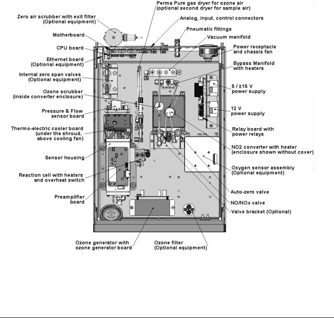
Getting Started |
Teledyne API - Model 200EH/EM Operation Manual |
VENTILATION CLEARANCE: Whether the analyzer is set up on a bench or installed into an instrument rack, be sure to leave sufficient ventilation clearance.
AREA |
MINIMUM REQUIRED CLEARANCE |
Back of the instrument |
10 cm / 4 inches |
Sides of the instrument |
2.5 cm / 1 inch |
Above and below the instrument. |
2.5 cm / 1 inch |
|
|
Various rack mount kits are available for this analyzer. See Chapter 5 of this manual for more information.
3.1.1. M200EH/EM LAYOUT
Figure 3-1 shows a top-down view of the analyzer. The shown configuration includes the Ethernet board, IZS option, zero-air scrubber and an additional sample dryer. See Chapter 5 for optional equipment. Figure 3-2 shows the rear panel configuration with optional zero-air scrubber mounted to it and two optional fittings for the IZS option. Figure 3-3, finally shows the front panel layout of the analyzer.
Figure 3-1: M200EH/EM Layout
8
04521C (DCN5731)

Teledyne API - Model 200EH/EM Operation Manual |
Getting Started |
ALARM OUT
AL1 AL2 AL3 AL4
NO C NC NO C NC NO C |
NC |
Figure 3-2: M200EH/EM Rear Panel Layout
Figure 3-3: M200EH/EM Front Panel Layout
9
04521C (DCN5731)
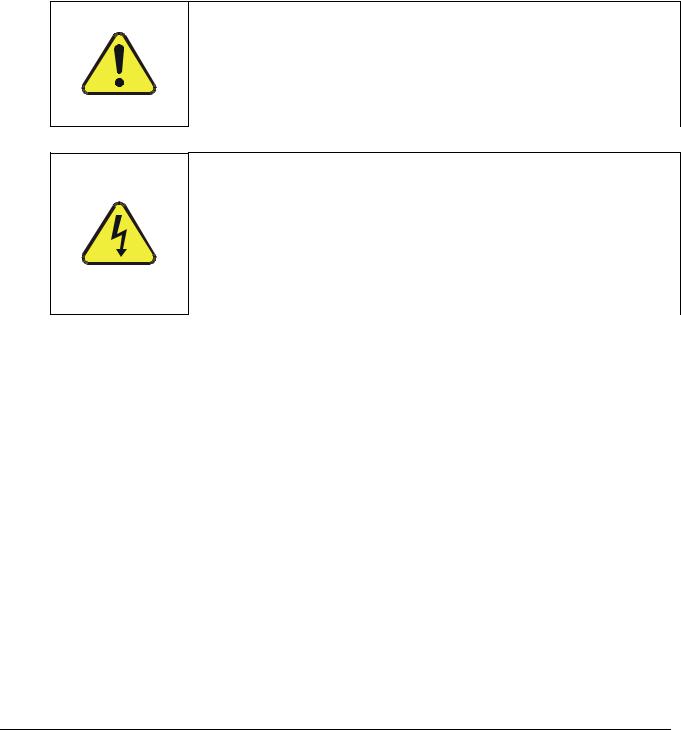
Getting Started |
Teledyne API - Model 200EH/EM Operation Manual |
3.1.2. ELECTRICAL CONNECTIONS
Refer to Figure 3-2 for the location of the rear panel electrical and pneumatic connections.
3.1.2.1. Power Connection
Attach the power cord to the analyzer and plug it into a power outlet capable of carrying at least 10 A current at your AC voltage and that it is equipped with a functioning earth ground.
CAUTION
CHECK THE VOLTAGE AND FREQUENCY LABEL ON THE REAR PANEL OF THE INSTRUMENT (SEE FIGURE 3-2 FOR COMPATIBILITY WITH THE LOCAL POWER BEFORE PLUGGING THE M200EH/EM INTO LINE POWER.
Do not plug in the power cord if the voltage or frequency is incorrect.
CAUTION
POWER CONNECTION MUST HAVE FUNCTIONING GROUND
CONNECTION.
DO NOT DEFEAT THE GROUND WIRE ON POWER PLUG.
TURN OFF ANALYZER POWER BEFORE DISCONNECTING OR
CONNECTING ELECTRICAL SUBASSEMBLIES.
DO NOT OPERATE WITH COVER OFF.
The M200EH/EM analyzer can be configured for both 100-130 V and 210-240 V at either 50 or 60 Hz., To avoid damage to your analyzer, make sure that the AC power voltage matches the voltage indicated on the rear panel serial number label and that the frequency is between 47 and 63 Hz.
10
04521C (DCN5731)

Teledyne API - Model 200EH/EM Operation Manual |
Getting Started |
3.1.2.2. Analog Output Connections
The M200H/EM is equipped with four analog output channels accessible through a connector on the back panel of the instrument. Each of these outputs may be set to reflect the value of any of the instrument’s iDAS data types. (see Table A-6 of M200EH/EM Appendix A – P/N 05147).
The following table lists the default settings for each of these channels. To change these settings, see Sections 6.13.4
Table 3-1: Analog Output Data Type Default Settings
PARAMETER |
|
CHANNEL DEFAULT SETTING |
|
|||
A1 |
A2 |
|
A3 |
A43 |
||
|
|
|
||||
|
DATA TYPE1 |
NXCNC1 |
NOCNC1 |
|
N2CNC1 |
NXCNC2 |
|
RANGE |
|
0 - 5 VDC2 |
|
|
|
|
REC OFS |
|
0 mVDC |
|
|
|
|
|
|
|
|
|
|
|
AUTO CAL. |
|
ON |
|
|
|
|
|
|
|
|
||
CALIBRATED |
|
NO |
|
|
||
|
OUTPUT |
|
ON |
|
|
|
|
SCALE |
|
100 ppm |
|
|
|
|
|
|
|
|
|
|
|
UPDATE |
|
5 sec |
|
|
|
|
|
|
|
|
|
|
1 |
See Table A-6 of M200EH/EM Appendix A for definitions of these iDAS data types |
|
||||
2 |
Optional current loop outputs are available for analog output channels A1-A3. |
|
||||
3 |
On analyzers with O2 sensor options installed, iDAS parameter O2CONC is assigned to output A4. |
|||||
To access these signals attach a strip chart recorder and/or data-logger to the appropriate contacts of the analog output connecter on the rear panel of the analyzer.
|
|
|
ANALOG OUT |
|
|
|
|
|
|
A1 |
A2 |
A3 |
A4 |
||
|
+ - |
+ - |
+ - |
+ - |
|
|
|
|
|
||||||
|
|
|
|
|
|
|
|
|
|
|
|
|
|
|
|
|
|
|
|
|
|
|
|
|
Figure 3-4: |
Analog Output Connector |
|||
|
Table 3-2: Analog Output Pin-Outs |
|
|||
|
|
|
|
|
|
PIN |
ANALOG OUTPUT |
|
VOLTAGE SIGNAL |
|
CURRENT SIGNAL |
1 |
A1 |
|
V Out |
|
I Out + |
2 |
|
|
Ground |
|
I Out - |
3 |
A2 |
|
V Out |
|
I Out + |
4 |
|
|
Ground |
|
I Out - |
|
|
|
|
|
|
5 |
A3 |
|
V Out |
|
I Out + |
|
|
|
|
|
|
6 |
|
|
Ground |
|
I Out - |
7 |
A4 |
|
V Out |
|
I Out + |
8 |
|
|
Ground |
|
I Out - |
|
|
|
|
|
|
11
04521C (DCN5731)
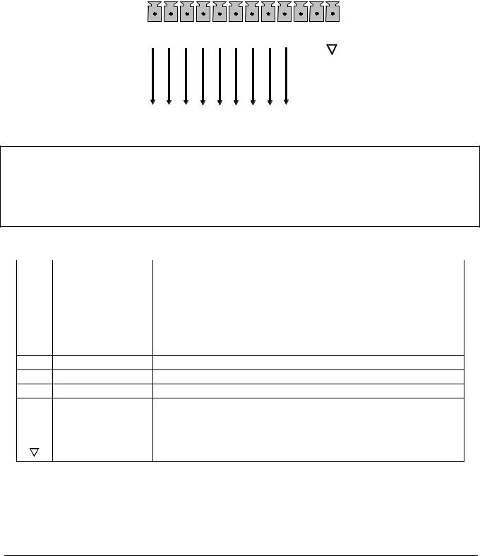
Getting Started |
Teledyne API - Model 200EH/EM Operation Manual |
3.1.2.3. Connecting the Status Outputs
If you wish to utilize the analyzer’s status outputs to interface with a device that accepts logic-level digital inputs, such as programmable logic controller (PLC) chips, you can access them through a 12 pin connector on the analyzer’s rear panel labeled STATUS.
STATUS
|
|
|
|
|
|
|
|
|
|
|
|
|
|
|
|
|
|
|
|
|
|
|
|
|
|
|
|
|
|
|
|
|
|
|
|
|
|
|
|
|
|
|
1 |
2 |
3 |
|
4 |
5 |
6 |
7 |
8 |
D |
+ |
|
|
|
|
|
|
||||||||||
|
|
|
|
||||||||||
|
SYSTEM OK |
CONC VALID |
HIGH RANGE |
ZERO CAL |
SPAN CAL |
|
DIAGNOSTIC MODE |
LOW SPAN |
|
EMITTER BUS FOR PINS 1-8 |
|
|
|
Figure 3-5: Status Output Connector
NOTE
Most PLC’s have internal provisions for limiting the current the input will draw. When connecting to a unit that does not have this feature, external resistors must be used to limit the current through the individual transistor outputs to ≤50mA (120 Ω for 5V supply).
|
|
Table 3-3: Status Output Signals |
|
|
|
|
|
PIN # |
STATUS |
CONDITION (ON = CONDUCTING) |
|
1 |
SYSTEM OK |
ON if no faults are present. |
|
2 |
CONC VALID |
ON if concentration measurement (NO, NO2 or NOx) is valid. |
|
OFF any time the hold-off feature is active. |
|||
|
|
||
3 |
HIGH RANGE |
ON if unit is in high range of the Auto Range Mode. |
|
4 |
ZERO CAL |
ON whenever the instrument is in ZERO point calibration mode. |
|
5 |
SPAN CAL |
ON whenever the instrument is in SPAN point calibration mode. |
6DIAG MODE ON whenever the instrument is in diagnostic mode.
7LOW SPAN CAL ON when in low span calibration (optional equipment necessary)
8Unused
D |
EMITTER BUS |
The emitters of the transistors on pins 1-8 are tied together. |
|
|
|
Unused |
|
+ |
DC POWER |
+ 5 VDC, 300 mA (combined rating with Control Output, if used). |
|
|
|
Digital Ground |
The ground level from the analyzer’s internal DC power supplies |
|
|
||
|
|
||
12
04521C (DCN5731)
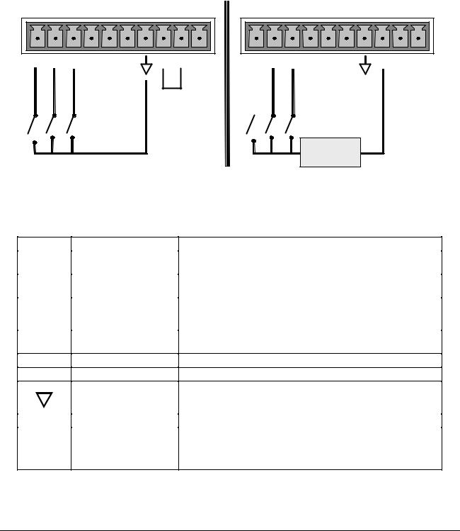
Teledyne API - Model 200EH/EM Operation Manual |
Getting Started |
3.1.2.4. Connecting the Control Inputs
If you wish to use the analyzer to remotely activate the zero and span calibration modes, several digital control inputs are provided through a 10-pin connector labeled CONTROL IN on the analyzer’s rear panel.
There are two methods for energizing the control inputs. The internal +5V available from the pin labeled “+” is the most convenient method. However, if full isolation is required, an external 5 VDC power supply should be used.
CONTROL IN
A |
B |
C |
D |
E |
F |
U |
+ |
CAL |
CAL |
ZERO |
|
CONTROL IN
A |
B |
C |
D |
E |
F |
U |
+ |
ZERO CAL
5 VDC Power
- Supply +
Local Power Connections |
External Power Connections |
Figure 3-6: Control Input Connector
Table 3-4: Control Input Signals
INPUT # |
STATUS DEFINITION |
ON CONDITION |
|
A |
REMOTE ZERO CAL |
The analyzer is placed in Zero Calibration mode. The mode field of |
|
the display will read ZERO CAL R. |
|||
|
|
||
B |
REMOTE SPAN CAL |
The analyzer is placed in Span Calibration mode. The mode field of |
|
the display will read SPAN CAL R. |
|||
|
|
||
|
|
The analyzer is placed in low span calibration mode as part of |
|
C |
REMOTE LO SPAN CAL |
performing a low span (midpoint) calibration. The mode field of the |
|
|
|
display will read LO CAL R. |
|
D |
REMOTE RANGE HI |
The analyzer is placed into high range when configured for dual |
|
ranges.. |
|||
|
|
ESPARE
FSPARE
|
|
Digital Ground |
The ground level from the analyzer’s internal DC power supplies |
|
|
|
|||
|
|
(same as chassis ground). |
||
|
|
|
||
|
|
|
||
U |
External Power input |
Input pin for +5 VDC required to activate pins A - F. |
||
|
|
|
Internally generated 5V DC power. To activate inputs A - F, place a |
|
+ |
5 VDC output |
jumper between this pin and the “U” pin. The maximum amperage |
||
through this port is 300 mA (combined with the analog output supply, |
||||
|
|
|
||
|
|
|
if used). |
|
13
04521C (DCN5731)

Getting Started |
Teledyne API - Model 200EH/EM Operation Manual |
3.1.2.5. Connecting the Serial Ports
If you wish to utilize either of the analyzer’s two serial interfaces, refer to Section 6.11 and 6.15 of this manual for instructions on configuration and usage.
3.1.2.6. Connecting to a LAN or the Internet
If your unit has a Teledyne Instruments Ethernet card (Option 63), plug one end of a 7’ CAT5 cable into the appropriate place on the back of the analyzer (see Figure 5-11 in Section 5.9.3) and the other end into any nearby Ethernet access port.
NOTE:
The M200EH/EM firmware supports dynamic IP addressing or DHCP.
If your network also supports DHCP, the analyzer will automatically configure its LAN connection appropriately,
If your network does not support DHCP, see Section 6.11.6.3 for instructions on manually configuring the LAN connection.
3.1.2.7. Connecting to a Multidrop Network
If your unit has a Teledyne Instruments RS-232 multidrop card (Option 62), see Section 6.11.7 for instructions on setting it up.
CAUTION
To prevent dust from getting into the analyzer, it was shipped with small plugs inserted into each of the pneumatic fittings on the rear panel. Make sure that all dust plugs are removed before attaching exhaust and supply gas lines.
14
04521C (DCN5731)
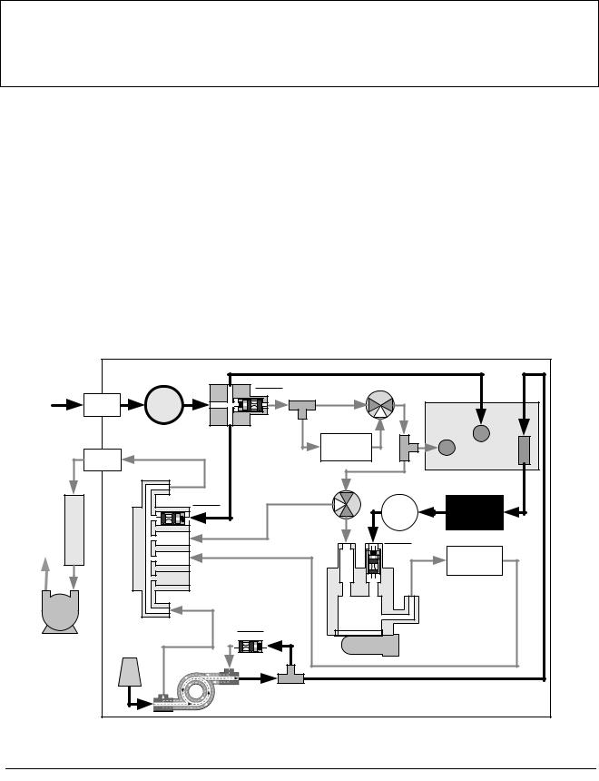
Teledyne API - Model 200EH/EM Operation Manual |
Getting Started |
3.1.3. PNEUMATIC CONNECTIONS
NOTE
To prevent dust from getting into the analyzer, it was shipped with small plugs inserted into each of the pneumatic fittings on the rear panel. Make sure that all dust plugs are removed before attaching exhaust and supply gas lines.
Table 3-5: Inlet / Outlet Connector Nomenclature
REAR PANEL LABEL |
FUNCTION |
|
SAMPLE |
Connects the sample gas to the analyzer. When operating the analyzer |
|
without zero span option, this is also the inlet for any calibration gases. |
||
|
||
EXHAUST |
Connects the exhaust of the analyzer with the external vacuum pump. |
|
SPAN |
On Units with zero/span valve or IZS option installed, this port connects the |
|
external calibration gas to the analyzer. |
||
|
||
ZERO AIR |
On Units with zero/span valve or IZS option installed, this port connects the |
|
zero air gas or the zero air cartridge to the analyzer. |
||
|
Figure 3-7 and 3.8 show the internal pneumatic flow of the standard configuration of the M200EH and M200EM respectively.
Figure 3-7: M200EH Internal Pneumatic Block Diagram - Standard Configuration
15
04521C (DCN5731)
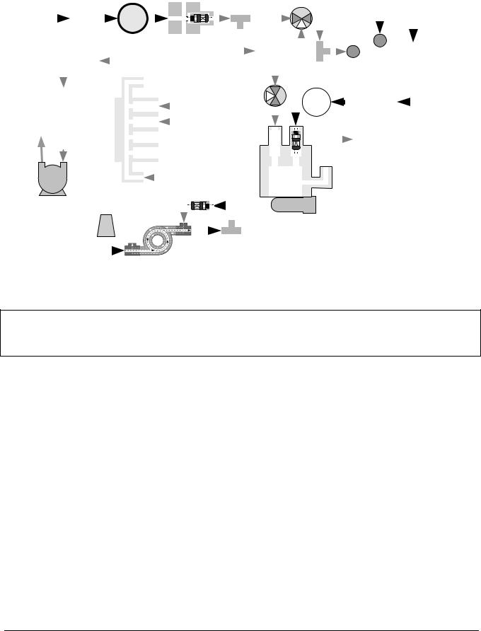
Getting Started |
|
|
|
|
|
|
|
|
|
|
|
|
|
|
|
|
|
|
|
Teledyne API - Model 200EH/EM Operation Manual |
|||||||||||||||||||||||||||||||||||||||||||||||||||
|
|
|
|
|
|
|
|
|
|
|
|
|
|
|
|
|
|
|
|
|
|
|
|
|
|
|
|
|
|
|
|
|
|
|
|
|
|
|
|
|
|
|
|
|
|
|
|
|
|
|
|
|
|
|
|
|
|
|
|
|
|
|
|
|
|
|
|
|
|
|
|
|
|
|
|
|
|
|
|
|
|
|
|
|
|
|
|
|
|
|
|
|
|
|
|
|
|
|
|
|
|
|
|
|
|
|
|
|
|
|
|
|
|
|
|
|
|
|
|
|
|
|
|
|
|
|
|
|
|
|
|
|
|
|
|
|
|
|
|
|
|
|
|
|
|
|
|
|
|
|
|
|
|
|
|
|
|
|
|
|
|
|
|
|
|
|
|
|
|
|
|
|
|
|
|
|
|
|
|
|
|
|
|
|
|
|
|
|
|
|
|
|
|
|
|
|
|
|
|
|
|
|
|
|
|
|
|
|
|
|
|
|
|
|
|
|
|
|
|
|
|
|
|
|
|
|
|
|
|
|
|
|
|
|
|
|
|
|
|
|
|
|
|
|
|
|
|
|
|
|
|
|
|
|
|
|
|
|
|
|
|
|
|
|
|
|
|
|
|
|
|
|
|
|
|
|
|
|
|
|
|
|
|
|
|
|
|
|
|
|
|
|
|
|
|
|
|
|
|
|
|
|
|
|
|
|
|
|
|
|
|
|
|
|
|
|
|
|
|
|
|
|
|
|
|
|
|
|
|
|
|
|
|
|
|
|
|
|
|
|
|
|
|
|
|
|
|
|
|
|
|
|
|
|
|
|
|
|
|
|
|
|
|
|
|
|
|
|
|
|
|
|
|
|
|
|
|
|
|
|
|
|
|
|
|
|
|
|
|
|
|
|
|
|
|
|
|
|
|
|
|
|
|
|
|
|
|
|
|
|
|
|
|
|
|
|
|
|
|
|
|
|
|
|
|
|
|
|
|
|
|
|
|
|
|
|
|
|
|
|
|
|
|
|
|
|
|
|
|
|
|
|
|
|
|
|
|
|
|
|
|
|
|
|
|
|
|
|
|
|
|
|
|
|
|
|
|
|
|
|
|
|
|
|
|
|
|
|
|
|
|
|
|
|
|
|
|
|
|
|
|
|
|
|
|
|
|
|
|
|
|
|
|
|
|
|
|
|
|
|
|
|
|
|
|
|
|
|
|
|
|
|
|
|
|
|
|
|
|
|
|
|
|
|
|
|
|
|
|
|
|
|
|
|
|
|
|
|
|
|
|
|
|
|
|
|
|
|
|
|
|
|
|
|
|
|
|
|
|
|
|
|
|
|
|
|
|
|
|
|
|
|
|
|
|
|
|
|
|
|
|
|
|
|
|
|
|
|
|
|
|
|
|
|
|
|
|
|
|
|
|
|
|
|
|
|
|
|
|
|
|
|
|
|
|
|
|
|
|
|
|
|
|
|
|
|
|
|
|
|
|
|
|
|
|
|
|
|
|
|
|
|
|
|
|
|
|
|
|
|
|
|
|
|
|
|
|
|
|
|
|
|
|
|
|
|
|
|
|
|
|
|
|
|
|
|
|
|
|
|
|
|
|
|
|
|
|
|
|
|
|
|
|
|
|
|
|
|
|
|
|
|
|
|
|
|
|
|
|
|
|
|
|
|
|
|
|
|
|
|
|
|
|
|
|
|
|
|
|
|
|
|
|
|
|
|
|
|
|
|
|
|
|
|
|
|
|
|
|
|
|
|
|
|
|
|
|
|
|
|
|
|
|
|
|
|
|
|
|
|
|
|
|
|
|
|
|
|
|
|
|
|
|
|
|
|
|
|
|
|
|
|
|
|
|
|
|
|
|
|
|
|
|
|
|
|
|
|
|
|
|
|
|
|
|
|
|
|
|
|
|
|
|
|
|
|
|
|
|
|
|
|
|
|
|
|
|
|
|
|
|
|
|
|
|
|
|
|
|
|
|
|
|
|
|
|
|
|
|
|
|
|
|
|
|
|
|
|
|
|
|
|
|
|
|
|
|
|
|
|
|
|
|
|
|
|
|
|
|
|
|
|
|
|
|
|
|
|
|
|
|
|
|
|
|
|
|
|
|
|
|
|
|
|
|
|
|
|
|
|
|
|
|
|
|
|
|
|
|
|
|
|
|
|
|
|
|
|
|
|
|
|
|
|
|
|
|
|
|
|
|
|
|
|
|
|
|
|
|
|
|
|
|
|
|
|
|
|
|
|
|
|
|
|
|
|
|
|
|
|
|
|
|
|
|
|
|
|
|
|
|
|
|
|
|
|
|
|
|
|
|
|
|
|
|
|
|
|
|
|
|
|
|
|
|
|
|
|
|
|
|
|
|
|
|
|
|
|
|
|
|
|
|
|
|
|
|
|
|
|
|
|
|
|
|
|
|
|
|
|
|
|
|
|
|
|
|
|
|
|
|
|
|
|
|
|
|
|
|
|
|
|
|
|
|
|
|
|
|
|
|
|
|
|
|
|
|
|
|
|
|
|
|
|
|
|
|
|
|
|
|
|
|
|
|
|
|
|
|
|
|
|
|
|
|
|
|
|
|
|
|
|
|
|
|
|
|
|
|
|
|
|
|
|
|
|
|
|
|
|
|
|
|
|
|
|
|
|
|
|
|
|
|
|
|
|
|
|
|
|
|
|
|
|
|
|
|
|
|
|
|
|
|
|
|
|
|
|
|
|
|
|
|
|
|
|
|
|
|
|
|
|
|
|
|
|
|
|
|
|
|
|
|
|
|
|
|
|
|
|
|
|
|
|
|
|
|
|
|
|
|
|
|
|
|
|
|
|
|
|
|
|
|
|
|
|
|
|
|
|
|
|
|
|
|
|
|
|
|
|
|
|
|
|
|
|
|
|
|
|
|
|
|
|
|
|
|
|
|
|
|
|
|
|
|
|
|
|
|
|
|
|
|
|
|
|
|
|
|
|
|
|
|
|
|
|
|
|
|
|
|
|
|
|
|
|
|
|
|
|
|
|
|
|
|
|
|
|
|
|
|
|
|
|
|
|
|
|
|
|
|
|
|
|
|
|
|
|
|
|
|
|
|
|
|
|
|
|
|
|
|
|
|
|
|
|
|
|
|
|
|
|
|
|
|
|
|
|
|
|
|
|
|
|
|
|
|
|
|
|
|
|
|
|
|
|
|
|
|
|
|
|
|
|
|
|
|
|
|
|
|
|
|
|
|
|
|
|
|
|
|
|
|
|
|
|
|
|
|
|
|
|
|
|
|
|
|
|
|
|
|
|
|
|
|
|
|
|
|
|
|
|
|
|
|
|
|
|
|
|
|
|
|
|
|
|
|
|
|
|
|
|
|
|
|
|
|
|
|
|
|
|
|
|
|
|
|
|
|
|
|
|
|
|
|
|
|
|
|
|
|
|
|
|
|
|
|
|
|
|
|
|
|
|
|
|
|
|
|
|
|
|
|
|
|
|
|
|
|
|
|
|
|
|
|
|
|
|
|
|
|
|
|
|
|
|
|
|
|
|
|
|
|
|
|
|
|
|
|
|
|
|
|
|
|
|
|
|
|
|
|
|
|
|
|
|
|
|
|
|
|
|
|
|
|
|
|
|
|
|
|
|
|
|
|
|
|
|
|
|
|
|
|
|
|
|
|
|
|
|
|
|
|
|
|
|
|
|
|
|
|
|
|
|
|
|
|
|
|
|
|
|
|
|
|
|
|
|
|
|
|
|
|
|
|
|
|
|
|
|
|
|
|
|
|
|
|
|
|
|
|
|
|
|
|
|
|
|
|
|
|
|
|
|
|
|
|
|
|
|
|
|
|
|
|
|
|
|
|
|
|
|
|
|
|
|
|
|
|
|
|
|
|
|
|
|
|
|
|
|
|
|
|
|
|
|
|
|
|
|
|
|
|
|
|
|
|
|
|
|
|
|
|
|
|
|
|
|
|
|
|
|
|
|
|
|
|
|
|
|
|
|
|
|
|
|
|
|
|
|
|
|
|
|
|
|
|
|
|
|
|
|
|
|
|
|
|
|
|
|
|
|
|
|
|
|
|
|
|
|
|
|
|
|
|
|
|
|
|
|
|
|
|
|
|
|
|
|
|
|
|
|
|
|
|
|
|
|
|
|
|
|
|
|
|
|
|
|
|
|
|
|
|
|
|
|
|
|
|
|
|
|
|
|
|
|
|
|
|
|
|
|
|
|
|
|
|
|
|
|
|
|
|
|
|
|
|
|
|
|
|
|
|
|
|
|
|
|
|
|
|
|
|
|
|
|
|
|
|
|
|
|
|
|
|
|
|
|
|
|
|
|
|
|
|
|
|
|
|
|
|
|
|
|
|
|
|
|
|
|
|
|
|
|
|
|
|
|
|
|
|
|
|
|
|
|
|
|
|
|
|
|
|
|
|
|
|
|
|
|
|
|
|
|
|
|
|
|
|
|
|
|
|
|
|
|
|
|
|
|
|
|
|
|
|
|
|
|
|
|
|
|
|
|
|
|
|
|
|
|
|
|
|
|
|
|
|
|
|
|
|
|
|
|
|
|
|
|
|
|
|
|
|
|
|
|
|
|
|
|
|
|
|
|
|
|
|
|
|
|
|
|
|
|
|
|
|
|
|
|
|
|
|
|
|
|
|
|
|
|
|
|
|
|
|
|
|
|
|
|
|
|
|
|
|
|
|
|
|
|
|
|
|
|
|
|
|
|
|
|
|
|
|
|
|
|
|
|
|
|
|
|
|
|
|
|
|
|
|
|
|
|
|
|
|
|
|
|
|
|
|
|
|
|
|
|
|
|
|
|
|
|
|
|
|
|
|
|
|
|
|
|
|
|
|
|
|
|
|
|
|
|
|
|
|
|
|
|
|
|
|
|
|
|
|
|
|
|
|
|
|
|
|
|
|
|
|
|
|
|
|
|
|
|
|
|
|
|
|
|
|
|
|
|
|
|
|
|
|
|
|
|
|
|
|
|
|
|
|
|
|
|
|
|
|
|
|
|
|
|
|
|
|
|
|
|
|
|
|
|
|
|
|
|
|
|
|
|
|
|
|
|
|
|
|
|
|
|
|
|
|
|
|
|
|
|
|
|
|
|
|
|
|
|
|
|
|
|
|
|
|
|
|
|
|
|
|
|
|
|
|
|
|
|
|
|
|
|
|
|
|
|
|
|
|
|
|
|
|
|
|
|
|
|
|
|
|
|
|
|
|
|
|
|
|
|
|
|
|
|
|
|
|
|
|
|
|
|
|
|
|
|
|
|
|
|
|
|
|
|
|
|
|
|
|
|
|
|
|
|
|
|
|
|
|
|
|
|
|
|
|
|
|
|
|
|
|
|
|
|
|
|
|
|
|
Figure 3-8: M200EM Internal Pneumatic Block Diagram - Standard Configuration
Note:
Pneumatic Diagrams do not reflect the physical layout of the instrument.
The most significant differences between the M200EH and M200 EM versions in regards to pneumatic flow are:
A bypass line leading directly from the bypass manifold to the exhaust manifold is present on the M200EH, but not in the M200EM.
The Diameter of the critical flow orifice controlling the gas flow into the sample chamber is smaller and therefore the flow rate of sample gas through the instrument is lower.
See Section 10.3.2 for more information on these differences
See Chapter 5 for or information on the pneumatic flow though instruments with one of the M200Eh/Em’available options installed.
3.1.3.1. Calibration Gases
Zero Air
Zero air or zero calibration gas is defined as a gas that is similar in chemical composition to the measured medium but without the gas to be measured by the analyzer, in this case NO and NO2. If your analyzer is equipped with an external zero air scrubber option, it is capable of creating zero air from ambient air.
16
04521C (DCN5731)
Loading...