


System Component
Operating Instructions
Model No. SC-HD510
SC-HD310
The illustrations show SC-HD510 for areas except Australia and N.Z.
EB 
 EP
EP 
 GN
GN
Note:
The “EB” indication shown on the outside packing case indicates United Kingdom.
Before connecting, operating or adjusting this product, please read these instructions completely. Please keep this manual for future reference.
RQT5296-B
Dear Customer
Thank you for purchasing this product.
For optimum performance and safety, please read these instructions carefully.
These operating instructions are applicable to the following systems.
These operating instructions, however, fundamentally explain the operation of system SC-HD510.
use |
|
|
|
|
System |
SC-HD510 |
SC-HD310 |
||
Before |
||||
Amplifier |
SE-HD510 |
SE-HD310 |
||
|
||||
|
|
|
|
|
|
Tuner |
ST-HD510 |
ST-HD310 |
|
|
|
|
|
|
|
CD player |
SL-HD510 |
SL-HD310 |
|
|
|
|
|
|
|
Cassette deck |
RS-HDA710 |
RS-HD310 |
|
|
|
|
|
|
|
Speakers |
SB-HD510 |
SB-HD310 |
|
|
|
|
|
CAUTION!
THIS PRODUCT UTILIZES A LASER.
USE OF CONTROLS OR ADJUSTMENTS OR PERFORMANCE OF PROCEDURES OTHER THAN THOSE SPECIFIED HEREIN MAY RESULT IN HAZARDOUS RADIATION EXPOSURE.
DO NOT OPEN COVERS AND DO NOT REPAIR YOURSELF. REFER SERVICING TO QUALIFIED PERSONNEL.
CAUTION!
DO NOT INSTALL OR PLACE THIS UNIT IN A BOOKCASE, BUILT IN CABINET OR IN ANOTHER CONFINED SPACE. ENSURE THE UNIT IS WELL VENTILATED. ENSURE THAT CURTAINS AND ANY OTHER MATERIALS DO NOT OBSTRUCT THE VENTILATION TO PREVENT RISK OF ELECTRIC SHOCK OR FIRE HAZARD DUE TO OVERHEATING.
CLASS 1
LASER PRODUCT
(Back of product)
(CD player)
DANGER |
INVISIBLE LASER RADIATION WHEN OPEN. |
|
AVOID DIRECT EXPOSURE TO BEAM. |
||
|
||
ADVARSEL |
USYNLIG LASERSTRÅLING VED ÅBNING, NÅR SIKKERHEDSAFBRYDERE |
|
|
ER UDE AF FUNKTION. UNDGÅ UDSÆTTELSE FOR STRÅLING. |
|
VARO! |
AVATTAESSA JA SUOJALUKITUS OHITETTAESSA OLET ALTTIINA |
|
NÄKYMÄTÖNTÄ LASERSÄTEILYLLE. ÄLÄ KATSO SÄTEESEEN. |
||
|
||
VARNING |
OSYNLIG LASERSTRÅLNING NÄR DENNA DEL ÄR ÖPPNAD OCH |
|
SPÄRREN ÄR URKOPPLAD. BETRAKTA EJ STRÅLEN. |
||
|
||
ADVARSEL |
USYNLIG LASERSTRÅLING NÅR DEKSEL ÅPNES OG SIKKERHEDSLÅS |
|
|
BRYTES. UNNGÅ EKSPONERING FOR STRÅLEN. |
|
VORSICHT |
UNSICHTBARE LASERSTRAHLUNG, WENN ABDECKUNG GEÖFFNET. |
|
|
NICHT DEM STRAHL AUSSETZEN. |
(Inside of product)
(Indersiden at apparatet)
(Tuotteen sisällä)
(Apparatens insida)
(Produktets innside)
(Im Inneren des Gerätes)
2
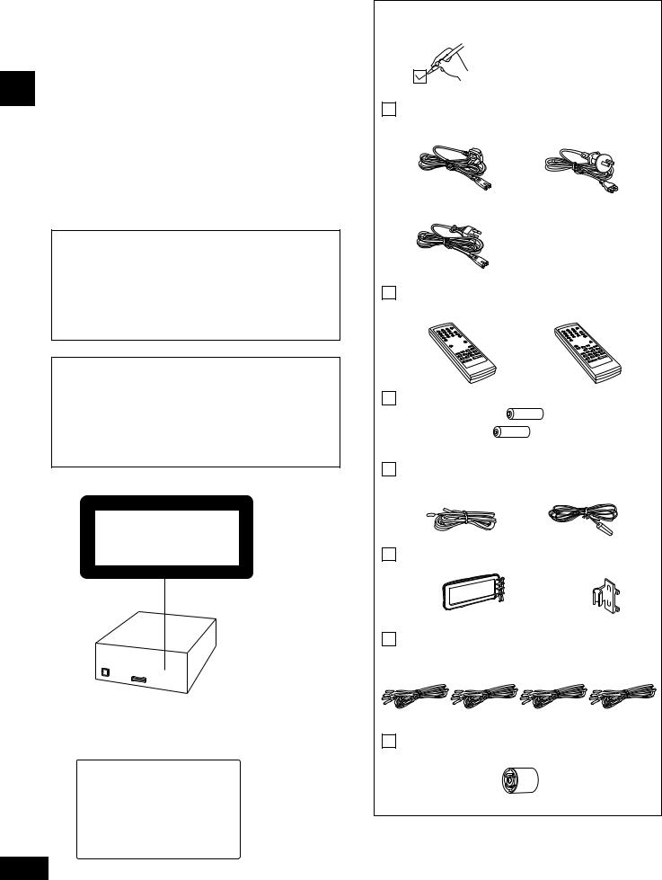
Supplied accessories
Please check and identify the supplied accessories.
AC mains lead............................................................. |
1 pc. |
For United Kingdom |
For Australia and N.Z. |
(RJA0053-2X) |
(RJA0035-K) |
For others (RJA0019-X)
Remote control ........................................................... |
1 pc. |
For Australia and N.Z. |
For others |
(RAK-HDA26WH) |
(RAK-HDA25WH) |
Remote control batteries ......................................... |
2 pcs. |
FM indoor antenna .................................................... |
1 pc. |
For Australia and N.Z. |
For others |
(RSA0006) |
(RSA0007) |
AM loop antenna set (RSA0022-J) ............................ |
1 pc. |
Speaker cords |
|
|
● Red and black (REE0499) ....................................... |
2 pcs. |
|
● Blue and gray (REE0853) |
|
2 pcs. |
SC-HD510 only |
||
Antenna plug adapter (SJP9009) |
..............................1 pc. |
(United Kingdom only) |
|
Use numbers indicated in parentheses when asking for replacement parts.
RQT5296

Table of contents |
|
Safety precautions |
|
|
|
Before use |
|
Safety precautions..................................................................... |
3 |
Caution for AC Mains Lead ..................................................... |
4 |
The remote control .................................................................... |
5 |
Installation.................................................................................... |
5 |
Connections ................................................................................ |
6 |
Front panel controls.................................................................. |
9 |
Turning the DEMO function off............................................ |
10 |
Setting the time ........................................................................ |
11 |
Saving power in standby mode ........................................... |
11 |
Radio operations |
|
The Radio: manual tuning ..................................................... |
12 |
The Radio: preset tuning ....................................................... |
13 |
Placement
Set the unit up on an even surface away from direct sunlight, high temperatures, high humidity, and excessive vibration. These conditions can damage the cabinet and other components, thereby shortening the unit’s service life.
Place it at least 15 cm away from wall surfaces to avoid distortion and unwanted acoustical effects.
Do not place heavy items on the unit.
Voltage
Do not use high voltage power sources. This can overload the unit and cause a fire.
Do not use a DC power source. Check the source carefully when setting the unit up on a ship or other place where DC is used.
Before use
Cassette deck operations |
|
Cassette tapes .......................................................................... |
14 |
Compact disc operations |
|
CDs |
|
Normal play ................................................................................. |
16 |
Other modes of play .................................................................... |
17 |
Recording operations |
|
Before recording ...................................................................... |
19 |
Preparatory steps ........................................................................ |
19 |
Recording the radio................................................................. |
20 |
Recording CDs |
|
Normal recording ......................................................................... |
20 |
One touch CD editing (AI EDIT) .................................................. |
21 |
Timer operations |
|
Using the timers |
|
The play timer.............................................................................. |
22 |
The record timer .......................................................................... |
23 |
The play and record timers.......................................................... |
24 |
The sleep timer............................................................................ |
24 |
Using the timers together ............................................................ |
24 |
Reference |
|
Using other equipment........................................................... |
25 |
Convenient functions ............................................................. |
26 |
Maintenance .............................................................................. |
26 |
Troubleshooting guide ........................................................... |
27 |
Technical specifications....................................... |
Back cover |
AC mains lead protection
Ensure the AC mains lead is connected correctly and not damaged. Poor connection and lead damage can cause fire or electric shock. Do not pull, bend, or place heavy items on the lead.
Grasp the plug firmly when unplugging the lead. Pulling the AC mains lead can cause electric shock.
Do not handle the plug with wet hands. This can cause electric shock.
Foreign matter
Do not let metal objects fall inside the unit. This can cause electric shock or malfunction.
Do not let liquids get into the unit. This can cause electric shock or malfunction. If this occurs, immediately disconnect the unit from the power supply and contact your dealer.
Do not spray insecticides onto or into the unit. They contain flammable gases which can ignite if sprayed into the unit.
Service
Do not attempt to repair this unit by yourself. If sound is interrupted, indicators fail to light, smoke appears, or any other problem that is not covered in these operating instructions occurs, disconnect the AC mains lead and contact your dealer or an authorized service center. Electric shock or damage to the unit can occur if the unit is repaired, disassembled or reconstructed by unqualified persons.
Extend operating life by disconnecting the unit from the power source if it is not to be used for a long time.
3
RQT5296
Before use
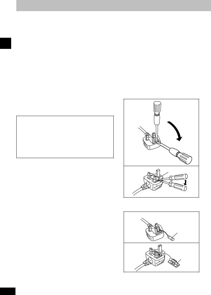
Caution for AC Mains Lead
(For United Kingdom)
(“EB” area code model only)
For your safety, please read the following text carefully.
This appliance is supplied with a moulded three pin mains plug for your safety and convenience.
A 5-ampere fuse is fitted in this plug.
Should the fuse need to be replaced please ensure that the replacement fuse has a rating of 5-ampere and that it is approved by ASTA or BSI to BS1362.
Check for the ASTA mark  or the BSI mark
  on the body of the fuse.
If the plug contains a removable fuse cover you must ensure that it is refitted when the fuse is replaced.
If you lose the fuse cover the plug must not be used until a replacement cover is obtained.
A replacement fuse cover can be purchased from your local dealer.
CAUTION!
IF THE FITTED MOULDED PLUG IS UNSUITABLE FOR THE SOCKET OUTLET IN YOUR HOME THEN THE FUSE SHOULD BE REMOVED AND THE PLUG CUT OFF AND DISPOSED OF SAFELY.
THERE IS A DANGER OF SEVERE ELECTRICAL SHOCK IF THE CUT OFF PLUG IS INSERTED INTO ANY 13-AMPERE SOCKET.
If a new plug is to be fitted please observe the wiring code as stated below.
If in any doubt please consult a qualified electrician.
IMPORTANT
The wires in this mains lead are coloured in accordance with the following code:
Blue: Neutral, Brown: Live.
As these colours may not correspond with the coloured markings identifying the terminals in your plug, proceed as follows:
The wire which is coloured Blue must be connected to the terminal which is marked with the letter N or coloured Black or Blue.
The wire which is coloured Brown must be connected to the terminal which is marked with the letter L or coloured Brown or Red.
WARNING: DO NOT CONNECT EITHER WIRE TO THE EARTH TERMINAL WHICH IS MARKED WITH THE LETTER E, BY THE EARTH SYMBOL  OR COLOURED GREEN OR GREEN/YELLOW.
THIS PLUG IS NOT WATERPROOF–KEEP DRY.
Before use
Remove the connector cover.
How to replace the fuse
The location of the fuse differ according to the type of AC mains plug (figures A and B). Confirm the AC mains plug fitted and follow the instructions below.
Illustrations may differ from actual AC mains plug.
1.Open the fuse cover with a screwdriver.
Figure A
Figure B |
Fuse cover |
2.Replace the fuse and close or attach the fuse cover.
Figure A
Fuse
(5 ampere)
Figure B
Fuse
(5 ampere)
4
RQT5296
A |
|
|
|
|
|
|
|
|
R6/LR6 |
|
|
|
1 |
(AA, UM-3) |
|
|
|
|
|
|
|
|
|
|
|
|
|
2 |
|
|
|
|
|
|
|
|
|
|
|
B |
|
|
|
|
|
|
30˚ |
30˚ |
|
|
7 m |
|
|
|
C |
|
|
|
|
aSL-HD510 bST-HD510 |
|
|||
|
/310 |
/310 |
|
|
cRS-HDA710/ |
|
fSB-HD510/310 |
||
|
RS-HD310 |
|
|
|
eSB-HD510/310 |
dSE-HD510/310 |
|
||
|
|
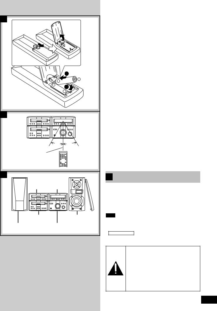
The remote control |
|
|
|
|
|
|
|
||
A |
|
Batteries |
|
|
|
Insert so the poles (+ and –) match those in the remote control. |
|
||||
Do not use rechargeable type batteries. |
|
||||
Do not; |
|
|
|
||
● mix old and new batteries. |
|
||||
|
|||||
● use different types at the same time. |
|
||||
● heat or expose to flame. |
|
||||
● take apart. |
|
||||
use |
|||||
● short circuit. |
|||||
● attempt to recharge alkaline or manganese batteries. |
|||||
Mishandling of batteries can cause electrolyte leakage which can |
Before |
||||
|
|||||
damage items the fluid contacts and may cause a fire. |
|
||||
If electrolyte leaks from the batteries, consult your dealer. |
|
||||
Wash thoroughly with water if electrolyte comes in contact with any |
|
||||
part of your body. |
|
||||
Remove if the remote control is not going to be used for a long |
|
||||
period of time. Store in a cool, dark place. |
|
||||
Replace if the unit does not respond to the remote control even |
|
||||
when held close to the front panel. |
|
||||
If the battery lid comes loose, slide it back into place horizontally. |
|
||||
|
|
|
|||
B |
|
Use |
|
|
|
|
|
|
|
|
|
Aim at the sensor, avoiding obstacles, at a maximum range of 7 meters directly in front of the unit.
●Keep the transmission window and the unit’s sensor free from dust.
●Operation can be affected by strong light sources, such as direct sunlight, and the glass doors on cabinets.
Do not;
●put heavy objects on the remote control.
●take the remote control apart.
●spill liquids onto the remote control.
C Installation
a CD player b Tuner
c Cassette deck d Amplifier
e Left speaker f Right speaker
Note
●These speakers do not have magnetic shielding. Do not place them near televisions, personal computers or other devices easily influenced by magnetism.
●SC-HD310 only
Left and right speakers are exactly the same.
Caution
●Use the speakers only with the recommended system. Failure to do so can damage the amplifier and speakers, and can cause fire. Consult a qualified service person if damage occurs or if a sudden change in performance is apparent.
●Do not attach these speakers to walls or ceilings.
5
RQT5296
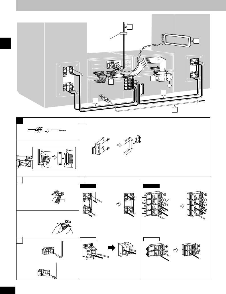
Connections
Unless otherwise marked, the illustrations show SC-HD510 sold outside Australia and New Zealand.
2
Adhesive tape
Before use
 1
1
(Right) |
4 |
A |
3 |
a |
c |
b |
|
1 To connect cables |
4 |
Speaker |
|
SC-HD510 |
|
|
|
Blue (–) |
|
White line |
Gray (+) |
|
|
|
To unplug cables |
|
Red (+) |
Hold the connector from |
|
Black (–) |
|
|
|
both ends and pull it out. |
|
|
2 (For Australia and N.Z.) |
SC-HD310 |
|
|
|
|
FM ANT |
|
|
75Ω |
|
|
|
|
Red (+) |
(For others) |
|
Black (–) |
|
|
|
FM ANT |
|
|
75Ω |
|
|
6
3
1
c (Left)
4
To household 5 mains socket
Amplifier
SC-HD510
HIGH |
Gray (+) |
HIGH |
|
||
|
|
W |
|
Blue (–) |
|
|
Black (–) |
|
Red (+) |
|
|
SC-HD310
Red (+)
Black (–)
RQT5296
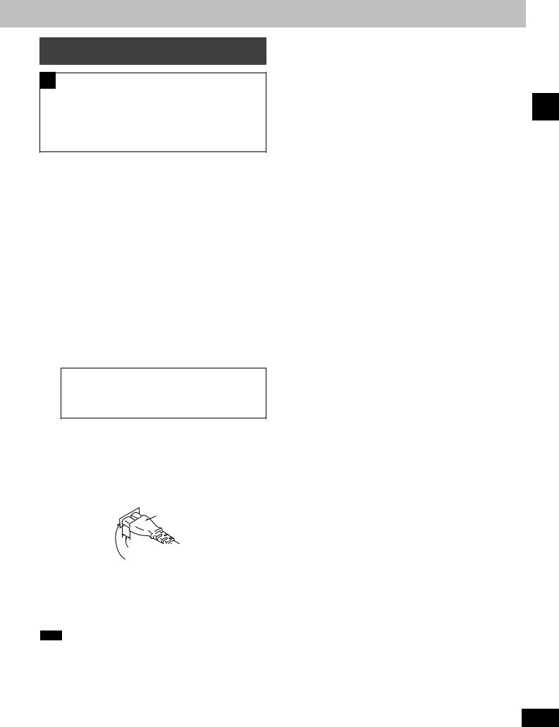
Basic connections for supplied accessories
A Before connection
● Do not connect the AC mains lead until all other connections are complete.
● To prepare the AM loop antenna, FM antenna (for Australia and N.Z.) and speaker cables, twist the vinyl tip and pull off (a).
● Disconnect the flat cable on the cassette deck (b).
1 Flat cables.
Keep the cables as flat as possible against the back of the unit.
2 FM antenna.
Fix the other end of the antenna where reception is best.
3 AM loop antenna.
Keep loose antenna cord away from other wires and cords.
4 Speaker cables.
Connect the cables to the terminals of the same color. Never allow the exposed wires to contact each other when connected.
Use only the supplied speakers.
The combination of the system and the front speakers provides the best sound. Using other speakers can damage the unit and sound quality will be negatively affected.
(United Kingdom only)
BE SURE TO READ THE CAUTION FOR THE AC MAINS LEAD ON PAGE 4 BEFORE PROCEEDING TO STEP 5.
5 Connect the AC mains lead.
Insertion of connector
Even when the connector is perfectly inserted, depending on the type of inlet used, the front part of the connector may jut out as shown in the drawing.
However there is no problem using the unit.
Connector
Approx. 6 mm
Appliance inlet
For your reference
Information you enter into the unit’s memory, except for time, remains intact for up to two weeks after the mains lead is disconnected.
Note
The included AC mains lead is for use with this unit only. Do not use it with other equipment.
Before use
7
RQT5296
Before use
A
a
DIGITAL

 OPTICAL
OUT
CD player
Tuner |
(R) |
(L) |
EXT/ OUT

MD IN

|
(R) |
(L) |
(R) |
(L) |
|
IN |
(L) |
|
OUT |
|
|
|
(R) |
|
|
|
|
|
|
|
|
|
|
|
|
|
|
|
|
|
MD deck, etc. |
|||||
DIGITAL |
(Recommended MD |
|||||||||
OPTICAL |
deck: SJ-HDA710) |
|||||||||
IN |
||||||||||
B |
Tuner |
FM outdoor antenna |
|
|
A |
75 Ω coaxial |
|
cable |
|
(not included) |
|
(For Australia and N.Z.) |
30 mm |
|
|
A |
|
|
15 mm |
(For others) |
(United Kingdom |
A |
only) |
|
|
|
Use the antenna |
|
plug adapter |
|
(included) |
C |
|
AM outdoor antenna |
Tuner |
5-12 m |
8
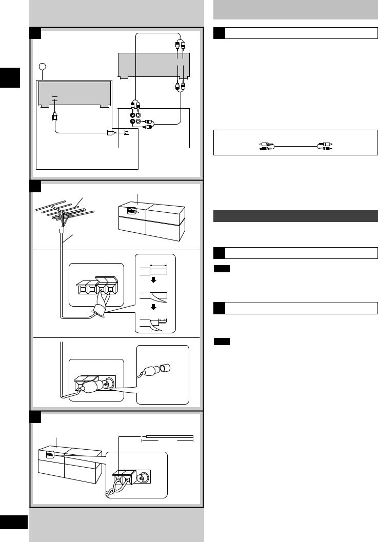
Connections
AExternal unit connections
●Turn off the power to all units before making connections.
●Refer to the manual of the other unit for details. (Cables and equipment not included.)
To listen to other equipment and make recordings
Connect other equipment to the EXT/MD IN terminals to output sound through this unit's speakers or to record onto the cassette deck. Connect this unit to other equipment through the EXT/MD OUT terminals to record onto another recording device or output from this unit through the other unit.
Connect DVD players to the EXT/MD IN terminal on the tuner.
Stereo phono cable (not included)
White (L)
Red (R)
To make digital recordings (a):
Remove the dust cap before use.
Use an optical fiber cable to connect other digital recording equipment to DIGITAL OPTICAL OUT on the back of the CD player.
This connection enables you to make digital recordings.
Optional antenna connections
Use outdoor antennas if radio reception is poor.
B FM outdoor antenna
Note
●Disconnect the FM indoor antenna.
●The antenna should be installed by a competent technician.
C AM outdoor antenna
Run a piece of vinyl wire horizontally across a window or other convenient location.
Note
●Leave the loop antenna connected.
●Disconnect the antenna when the unit is not in use. Do not use the antenna during an electrical storm.
RQT5296
A C
B 

A
|
|
|
1 |
|
|
2 |
|
|
|
|
|
|
OPEN/CLOSE |
|
CD TEXT |
SCROLL |
AI EDIT |
|
|
|
|
|
|
|
|||
3 |
4 |
5 |
6 |
7 |
8 |
9 |
B
|
|
|
10 |
|
|
|
11 |
|
|
|
|
|
|
|
OPEN/CLOSE |
|
COUNTER |
RESET |
|
REC PAUSE |
|
|
|
|
DOLBY NR REV MODE |
TPS SKIP |
|
[TPS] |
|
|
|
12 13 |
14 |
15 |
16 |
17 |
18 |
19 |
20 |
C
21
PLAY/ REC CLOCK/TIMER |
SET |
TUNE MODE |
RDS |
FM/AM |
TUNE/TIME ADJUST |
|
|
||
– DEMO |
|
|
|
|
22 23 24 25 26 27 28
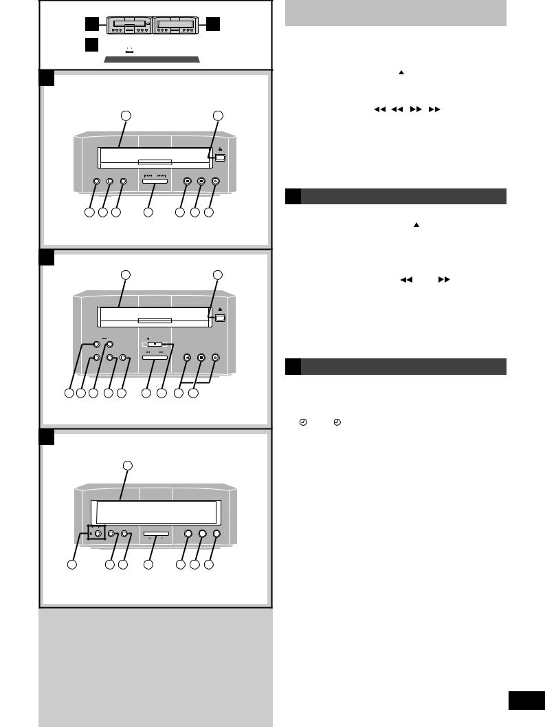
Front panel controls
A |
CD player |
|
|
|
|
|
|
|
|
|
||||||
q Disc tray |
|
|
|
|
|
|
|
|
|
|||||||
w Disc tray open/close button ( |
|
|
OPEN/CLOSE) |
..................16 |
|
|
||||||||||
...................................................e CD TEXT button (CD TEXT) |
|
|
|
|
|
16 |
|
|
||||||||
r Scroll button (SCROLL) |
......................................................... |
|
|
|
|
|
16 |
|
|
|||||||
|
|
|
|
|
|
|
||||||||||
t AI edit button (AI EDIT) .......................................................... |
|
|
|
|
|
|
21 |
|
|
|||||||
y Skip/search buttons ( |
|
|
/ |
, |
/ |
|
) |
16 |
|
|
||||||
|
|
|
|
|||||||||||||
|
|
|
|
|||||||||||||
u Stop button (■) |
|
|
|
|
|
|
16 |
|
|
|||||||
|
|
|
|
|
|
use |
||||||||||
i Pause button ( |
|
|
|
) |
|
|
|
|
|
|
|
|
16 |
|
||
|
|
|
|
|
|
|
|
|
||||||||
o Play button and indicator (u) |
|
|
|
|
|
16 |
|
|||||||||
|
|
|
|
|
|
Before |
||||||||||
The color of the indicator depends on the operation taking place. |
||||||||||||||||
If stopped: orange |
|
|
|
|
|
|
|
|
||||||||
If playing: green |
|
|
|
|
|
|
|
|
||||||||
B Cassette deck
!0Cassette holder |
|
|
|
|
!1Cassette tray open/close button ( |
|
OPEN/CLOSE) .......... |
14 |
|
...................................................!2Counter button (COUNTER) |
|
|
|
19 |
!3Dolby noise reduction button (DOLBY NR) |
.......................... |
14 |
||
!4Counter reset button (RESET) ............................................... |
|
|
|
14 |
!5Reverse mode select button (REV MODE) ........................... |
|
14 |
||
!6Tape Program Sensor button (TPS SKIP) ............................ |
|
15 |
||
!7Fast forward/rewind buttons ( |
[TPS] .................... |
) |
15 |
|
!8Record pause button and indicator (● REC .........PAUSE) |
20 |
|||
!9Playback buttons and indicators (v, u) .............................. |
|
14 |
||
The color of the indicator depends on the operation taking place.
If stopped, fast forwarding or rewinding: orange |
|
If playing, recording, or carrying out TPS: green |
|
@0Stop button (■) ...................................................................... |
14 |
C Tuner
@1Display panel
The display also shows information for the cassette deck, CD
|
player, and amplifier. |
|
||||
@2Play timer/record timer button and indicator |
|
|||||
|
( PLAY/ REC) ..................................................... |
22, 23, 24 |
||||
@3Clock/timer, demo button |
|
|||||
|
(CLOCK/TIMER, –DEMO)............................................ |
10, 11, 22 |
||||
@4Set button (SET)...................................................................... |
11 |
|||||
@5Tuning/time adjust buttons |
|
|||||
|
(TUNE/TIME ADJUST , ) ............................................. |
11,12 |
||||
@6Tuning mode button (TUNE MODE) ...................................... |
12 |
|||||
|
|
|
|
|||
|
SC-HD510 for areas except Australia and N.Z. |
|
||||
@7RDS button (RDS) ................................................................... |
12 |
|||||
@8Band select button (FM/AM) .................................................. |
12 |
|||||
|
|
|
|
|
|
|
|
SC-HD310 |
SC-HD510 for Australia and N.Z. |
|
|
|
|
@7FM band select button (FM) ................................................... |
12 |
|||||
@8AM band select button (AM) .................................................. |
12 |
|||||
9
RQT5296
 Loading...