


Model 382 (With RC25)
Slush Freezer
Operator’s Manual
053105-M
10/98

Complete this page for quick reference when service is required:
Taylor Distributor:
Address:
Phone:
Service:
Parts:
Date of Installation:
Information found on the 382 data label:
Model Number:
Serial Number:
Electrical Specs: |
Voltage |
|
Cycle |
|
|||||||
|
|
|
|
Phase |
|
|
|
|
|||
Maximum Fuse Size: |
|
|
|
Amps |
|||||||
Minimum Wire Ampacity: |
|
|
Amps |
||||||||
Part Number: |
|
|
|
|
|
|
|
|
|
||
Information found on RC25 data label: |
|
|
|
||||||||
Model Number: |
|
|
|
|
|
|
|
|
|
||
Serial Number: |
|
|
|
|
|
|
|
|
|
||
Electrical Specs: |
Voltage |
|
Cycle |
|
|||||||
|
|
|
|
Phase |
|
|
|
|
|||
Maximum Fuse Size: |
|
|
|
Amps |
|||||||
Minimum Wire Ampacity: |
|
|
|
Amps |
|||||||
E October, 1998 Taylor All rights reserved.
053105--M
The word Taylor and the Crown design
are registered trademarks in the United States of America and certain other countries.
Taylor Company
750 N. Blackhawk Blvd.
Rockton, IL 61072

|
|
Table of Contents |
Section 1 |
To the Installer . . . . . . . . . . . . . . . |
. . . . . . . . . . . . . . . . . . . . . . . . . . . . . 1 |
Installation Instructions . . . . . . . . . . . . . . . . . . . . |
. . . . . . . . . . . . . . . . . . . . . . . . . . . . . 1 |
|
Electrical Connections . . . . . . . . . . . . . . . . . . . . . |
. . . . . . . . . . . . . . . . . . . . . . . . . . . . 1 |
|
Section 2 |
To the Operator . . . . . . . . . . . . . . . |
. . . . . . . . . . . . . . . . . . . . . . . . . . . . 5 |
Compressor Warranty Disclaimer . . . . . . . . . . . |
. . . . . . . . . . . . . . . . . . . . . . . . . . . . 5 |
|
Section 3 |
Safety . . . . . . . . . . . . . . . . . . . . . . . . |
. . . . . . . . . . . . . . . . . . . . . . . . . . . . 6 |
Section 4 |
Operator Parts Identification . . . |
. . . . . . . . . . . . . . . . . . . . . . . . . . . . 7 |
Beater Door Assembly . . . . . . . . . . . . . . . . . . . . . |
. . . . . . . . . . . . . . . . . . . . . . . . . . . . 8 |
|
Accessories |
. . . . . . . . . . . . . . . . . . . . . . . . . . . . . . |
. . . . . . . . . . . . . . . . . . . . . . . . . . . . 9 |
Section 5 |
Important: To the Operator . . . . . |
. . . . . . . . . . . . . . . . . . . . . . . . . . . . 10 |
Symbol Legend . . . . . . . . . . . . . . . . . . . . . . . . . . . |
. . . . . . . . . . . . . . . . . . . . . . . . . . . . 10 |
|
Control Switch (Item 1) . . . . . . . . . . . . . . . . . . . . . |
. . . . . . . . . . . . . . . . . . . . . . . . . . . . 10 |
|
Fill Switch (Item 2) . . . . . . . . . . . . . . . . . . . . . . . . |
. . . . . . . . . . . . . . . . . . . . . . . . . . . . 11 |
|
Add Mix Light (Item 3) . . . . . . . . . . . . . . . . . . . . . |
. . . . . . . . . . . . . . . . . . . . . . . . . . . . 11 |
|
Mix Out Light (Item 4) . . . . . . . . . . . . . . . . . . . . . . |
. . . . . . . . . . . . . . . . . . . . . . . . . . . . 11 |
|
Viscosity Control (Item 5) . . . . . . . . . . . . . . . . . . . |
. . . . . . . . . . . . . . . . . . . . . . . . . . . . 11 |
|
Standby Switch (Optional) . . . . . . . . . . . . . . . . . . |
. . . . . . . . . . . . . . . . . . . . . . . . . . . . 11 |
|
Display Light Switch (Item 6) (Optional) . . . . . . |
. . . . . . . . . . . . . . . . . . . . . . . . . . . . 11 |
|
Push-Button Switch . . . . . . . . . . . . . . . . . . . . . . . . |
. . . . . . . . . . . . . . . . . . . . . . . . . . . . 11 |
|
Section 6 |
Operating Procedures . . . . . . . . . |
. . . . . . . . . . . . . . . . . . . . . . . . . . . . 12 |
Assembly . |
. . . . . . . . . . . . . . . . . . . . . . . . . . . . . . . |
. . . . . . . . . . . . . . . . . . . . . . . . . . . . 12 |
Sanitizing . |
. . . . . . . . . . . . . . . . . . . . . . . . . . . . . . . |
. . . . . . . . . . . . . . . . . . . . . . . . . . . . 16 |
Priming . . . |
. . . . . . . . . . . . . . . . . . . . . . . . . . . . . . . |
. . . . . . . . . . . . . . . . . . . . . . . . . . . . 17 |
Closing Procedure . . . . . . . . . . . . . . . . . . . . . . . . |
. . . . . . . . . . . . . . . . . . . . . . . . . . . . 18 |
|
Draining Product From The Freezing Cylinder |
. . . . . . . . . . . . . . . . . . . . . . . . . . . . 18 |
|
Rinsing . . . |
. . . . . . . . . . . . . . . . . . . . . . . . . . . . . . . |
. . . . . . . . . . . . . . . . . . . . . . . . . . . . 18 |
Cleaning . . |
. . . . . . . . . . . . . . . . . . . . . . . . . . . . . . . |
. . . . . . . . . . . . . . . . . . . . . . . . . . . . 19 |
Disassembly . . . . . . . . . . . . . . . . . . . . . . . . . . . . . . |
. . . . . . . . . . . . . . . . . . . . . . . . . . . . 20 |
|
Brush Cleaning . . . . . . . . . . . . . . . . . . . . . . . . . . . |
. . . . . . . . . . . . . . . . . . . . . . . . . . . . 20 |
|
Table of Contents |
Models 382RC25 |

Table of Contents - Page 2
Section 7 Important: Operator Checklist . . . . . . . . . . . . . . . . . . . . . . . . . . . . . . 21
During Cleaning and Sanitizing . . . . . . . . . . . . . . . . . . . . . . . . . . . . . . . . . . . . . . . . . 21
Troubleshooting Bacterial Count . . . . . . . . . . . . . . . . . . . . . . . . . . . . . . . . . . . . . . . . 21
Regular Maintenance Checks . . . . . . . . . . . . . . . . . . . . . . . . . . . . . . . . . . . . . . . . . . . 21
Winter Storage . . . . . . . . . . . . . . . . . . . . . . . . . . . . . . . . . . . . . . . . . . . . . . . . . . . . . . . . 21
Section 8 Troubleshooting Guide . . . . . . . . . . . . . . . . . . . . . . . . . . . . . . . . . . . . 22
Section 9 Parts Replacement Schedule . . . . . . . . . . . . . . . . . . . . . . . . . . . . . . . 25
Section 10 Parts List . . . . . . . . . . . . . . . . . . . . . . . . . . . . . . . . . . . . . . . . . . . . . . . . . 26
Wiring Diagrams . . . . . . . . . . . . . . . . . . . . . . . . . . . . . . . . . . . . . . . . . . . . . . . . . . . . . . 32
Note: Continuing research results in steady improvements; therefore, information in this manual is subject to change without notice.
Models 382/RC25 |
Table of Contents |

Section 1 |
To the Installer |
|
|
This machine is designed for indoor use only.
 DO NOT install the machine in an area where a water jet could be used to clean or rinse the machine. Failure to follow this instruction may result in serious electrical shock.
Installation Instructions
Preparation
Uncrate the condensing and dispensing units. After inspecting both units for damage, position them in the desired locations.
Electrical Connections
Individual power supplies are required for each unit. Check the data label on each unit for fuse, circuit ampacity, and electrical specifications. For proper power connections, refer to the wiring diagram provided inside of the electrical box.
In the United States, this equipment is intended to be installed in accordance with the National Electrical Code (NEC), ANSI/NFPA 70--1987. The purpose of the NEC code is the practical safeguarding of persons and property from hazards arising from the use of electricity. This code contains provisions considered necessary for safety. Compliance therewith and proper maintenance will result in an installation essentially free from hazard!
In all other areas of the world, equipment should be installed in accordance with the existing local codes. Please contact your local authorities.
Stationary appliances which are not equipped with a power cord and a plug or other device to disconnect the appliance from the power source must have an all--pole disconnecting device with a contact gap of at least 3 mm installed in the external installation.
 CAUTION: THIS EQUIPMENT MUST BE PROPERLY GROUNDED! FAILURE TO DO SO CAN RESULT IN SEVERE PERSONAL INJURY FROM ELECTRICAL SHOCK!
Beater rotation must be counterclockwise as viewed looking into the freezing cylinder of the Model 382 dispenser.
 NOTE: The following procedures should be performed by a trained service technician.
To correct rotation on a three-phase unit, exchange any two incoming power supply lines at the freezer main terminal block only.
To correct rotation on a single-phase unit, exchange the leads inside the beater motor. (Follow the diagram printed on the motor.)
Electrical connections are made directly to the splice box. The splice box is located behind the back panel.
IMPORTANT
Beater rotation on the 380 Series differs from other Taylor equipment.
050722
Models 382/RC25 |
1 |
To the Installer |
Refrigeration Charging and Line
Construction
The dispensing unit is shipped with a refrigerant holding charge that is sufficient enough to prevent moisture contamination (8 oz./227 g. HP62). This holding charge will become part of the total system charge.
The condensing unit is shipped with the total amount of refrigerant required for a typical installation of 75 ft. or less with a single dispenser. For other installation configurations, use the following chart for line sizing and for adding required refrigerant.
Recommended System Refrigerant
Charge
Domestic
Suction Line |
Dispenser |
Required Charge |
Length |
|
|
Less than 75 ft. |
Single |
10 lb. |
|
|
|
More than 75 ft. |
Single |
12 lb. (add 2 lb.) |
|
|
|
Less than 75 ft. |
Dual |
13 lb. (add 3 lb.) |
|
|
|
More than 75 ft. |
Dual |
15 lb. (add 5 lb.) |
|
|
|
International |
|
|
|
|
|
Suction Line |
Dispenser |
Required Charge |
Length |
|
|
Less than 22.8 m |
Single |
4.5 kg |
|
|
|
More than 22.8 m |
Single |
5.4 kg (add 0.91 kg) |
|
|
|
Less than 22.8 m |
Dual |
5.9 kg (add 1.4 kg) |
|
|
|
More than 22.8 m |
Dual |
6.8 kg (add 2.3 kg) |
|
|
|
Note: Maximum line length is 150 ft. (45.7 m).
Note: To meet individual installation requirements, lines must be purchased and constructed locally.
Line Size
Liquid Line - Single or dual dispensers require 3/8” refrigerant grade copper tubing (hard or soft).
Note: Insulating the liquid line is recommended if it is exposed to high ambient conditions. This will reduce heat accumulation and prevent the formation of flash gas in the liquid line.
Single Dispensing Installations
Suction Line - Less than 75 ft. (22.8 m) total line length requires 5/8” refrigerant grade copper tubing (hard or soft). Maximum 5/8” tubing length is 75 ft. (22.8 m).
Note: Suction lines must be insulated.
Suction Line - More than 75 ft. (22.8 m) total line length requires 3/4” refrigerant grade copper tubing (hard or soft). Maximum tubing length is 150 ft. (45.7 m).
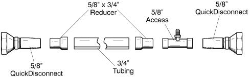
Dual Dispensing Installations (One Condenser, Two Dispensers)
Individual Suction Line - Requires 5/8” refrigeration grade copper tubing (hard or soft) from each dispenser to the common suction tube.
Common Suction Line - Requires 3/4” refrigeration grade copper tubing.
Note: Lines must be insulated and requires a 5/8” x 3/4” reducer fitting at the quick disconnect connections. See Figure 1 below.
Note: Use 5/8” wire to attach the quick disconnects to the other components. Figure 1
To the Installer |
2 |
Models 382/RC25 |
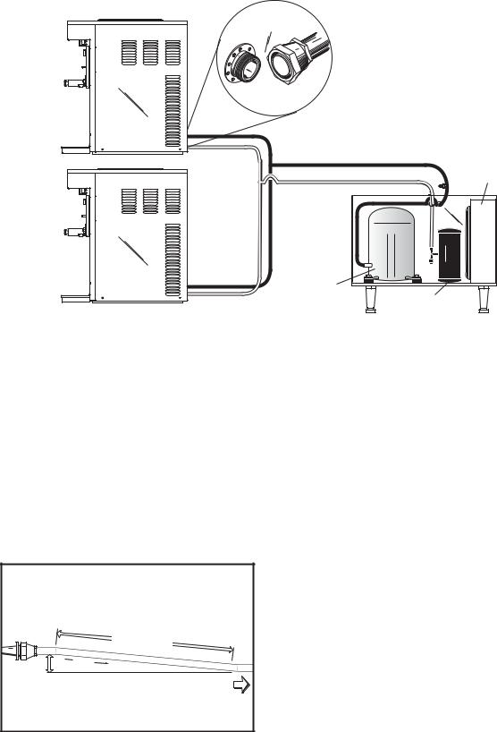
DISPENSER UNIT 382
Condenser
Access Valve 


|
Compressor |
|
Liquid Refrigerant |
DISPENSER UNIT |
Reciever |
382 |
CONDENSING UNIT |
|
Note: 5/8” individual line lengths are not to exceed 75 ft. (22.8 m) maximum length each.
Total line length is not to exceed 150 ft. (45.7 m). 5/8” line + 5/8” line + 3/4” line = 150 ft. or less. Figure 2
Installation
Step 1
Install refrigeration lines from the dispenser to the condensing unit. Do not create oil traps.
Note: For proper oil return, installation of horizontal suction lines are to be sloped downward in the direction of the condensing unit. The slope must be a minimum 1/4” (6.4 mm) angle per 10 ft. (30.48 mm) of line length.
FROM |
|
|
DISPENSER |
|
10'-0" |
|
|
|
|
(3.048 m) |
|
|
FLOW |
|
¼" (.64 cm) |
TO CONDENSER |
|
|
|
|
Figure 3
Normally, any straight run of tubing must be supported near each end of the run. Long runs require additional supports. As a guide, 3/8” to 3/4” copper should be supported every 5 ft. (1.5 m). When changing directions, no corner should be left unsupported. Supports should be placed a maximum of 2 ft. (.61 m) in each direction from the corner. If soft copper tube is used, make sure it is not kinked or flattened. If hard drawn copper tubing is used, use only long radius elbows.
Step 2
Braze the supplied quick connect/disconnect couplings on the dispenser end of the refrigeration lines. Couplings are supplied with the dispenser.
Step 3
Braze the quick connect/disconnect couplings and access tees on the condensing unit end of the refrigeration lines. Couplings and access tees are supplied with the unit.
Note: Wrap a wet cloth around the brass coupling bodies to prevent heat damage to the seal.
Step 4
Test the field constructed lines for leaks.
Models 382/RC25 |
3 |
To the Installer |
Step 5
Evacuate the field constructed refrigerant lines using the access fittings brazed on the condensing end of the refrigeration lines.
Step 6
When the evacuation process is complete, relieve the vacuum with 4 oz. (113 g.) of HP62 refrigerant per line, for a total of 8 oz. (227 g.) This procedure will prevent moisture contamination during dispenser and condensing unit connection and complete the total charge.
Refrigeration Connections
Connect the refrigerant line quick connect/disconnect couplings to the mating quick connect/disconnect couplings on the dispensing and condensing unit.
Step 1
Remove the shipping caps from the quick connect/disconnect coupling on the dispensing unit.
Step 2
Thoroughly clean and lubricate the mating surfaces of the quick connect/disconnects.
Note: Use polyolester oil to lubricate the surfaces.
Step 3
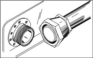
Manually thread the coupling halves together to insure proper mating of the threads.
Step 4
Using proper sized wrenches, tighten the coupling halves until the round, flat surfaces of inner coupling bodies completely depress one another.
Step 5
Once the flat surfaces are completely depressed, tighten the couplings an additional 1/4 turn. This step is necessary to insure that the knife edge of the seal seats into the brass seat of the coupling halves, forming a leak-proof joint (metal seal).
Figure 4
Step 6
Check all connections for leaks.
Step 7
Insulate all exposed suction line tubing and fittings.
Step 8
Set the pump down switch located in the condensing unit. For indoor condensing unit application:
Set cut in at 30 PSIG (207 kPa). Set cut out at 5 PSIG (34 kPa).
For outdoor condensing unit application:
Set cut in at 20 PSIG (138 kPa). Set cut out at 0 PSIG (0 kPa).
Pump down pressure readings are to be taken at the refrigeration line access fittings at the condensing unit.
Step 9
Allow the dispenser to run until the condensing unit cycles off. Verify the proper pump down pressure switch setting. See Step 8 of “Refrigeration Connections” (page 4).
Note: Pump down pressure readings are to be taken at the refrigeration line access fittings near the condensing unit.
Step 10
If necessary, adjust viscosity to produce satisfactory product. Adjustments are made by turning the viscosity adjustment screw (located under the control panel) clockwise for a thicker product or counterclockwise for a thinner product.
Set Up Procedures
Standard Fill Module
Step 1
Connect the product supply line to the 1/4” barbed fitting on the fill solenoid. Adjust the fill system pressure to deliver product to the hopper at approximately 15 to 20 PSIG (103-138 kPa).
Step 2
Lubricate, assemble, sanitize and prime the dispenser as outlined in the Assembly section of this manual.
Step 3
Place the power switch in the “AUTO” position.
Note: The fill switch must be in the “ON” position to enable refrigeration.
To the Installer |
4 |
Models 382/RC25 |

Section 2 |
To the Operator |
|
|
The freezer you have purchased has been carefully engineered and manufactured to give you dependable operation. The Taylor equipment, when properly operated and cared for, will produce a consistent quality product. Like all mechanical products, this machine will require cleaning and maintenance. A minimum amount of care and attention is necessary if the operating procedures outlined in this manual are followed closely.
This Operator’s Manual should be read before operating or performing any maintenance on your equipment.
Your Model 382 will NOT eventually compensate and correct for any errors during the set-up or filling operations. Thus, the initial assembly and priming procedures are of extreme importance. It is strongly recommended that all personnel responsible for the equipment’s operation thoroughly read this manual.
If you require technical assistance, please contact your local authorized Taylor Distributor.
 If the crossed out wheeled bin symbol is affixed to this product, it signifies that this product is compliant with the EU Directive as well as other similar legislation in effect after August 13, 2005. Therefore, it must be collected separately after its use is completed, and cannot be disposed as unsorted municipal waste.
The user is responsible for returning the product to the appropriate collection facility, as specified by your local code.
For additional information regarding applicable local laws, please contact the municipal facility and/or local distributor.
Compressor Warranty Disclaimer
The refrigeration compressor(s) on this machine are warranted for the term indicated on the warranty card accompanying this machine. However, due to the Montreal Protocol and the U.S. Clean Air Act Amendments of 1990, many new refrigerants are being tested and developed, thus seeking their way into the service industry. Some of these new refrigerants are being advertised as drop-in replacements for numerous applications. It should be noted that, in the event of ordinary service to this machine’s refrigeration system, only the refrigerant specified on the affixed data label should be used. The unauthorized use of alternate refrigerants will void your compressor warranty. It will be the owner’s responsibility to make this fact known to any technician he employs.
It should also be noted that Taylor does not warrant the refrigerant used in its equipment. For example, if the refrigerant is lost during the course of ordinary service to this machine, Taylor has no obligation to either supply or provide its replacement either at billable or unbillable terms. Taylor does have the obligation to recommend a suitable replacement if the original refrigerant is banned, obsoleted, or no longer available during the five year warranty of the compressor.
The Taylor Company will continue to monitor the industry and test new alternates as they are being developed. Should a new alternate prove, through our testing, that it would be accepted as a drop-in replacement, then the above disclaimer would become null and void. To find out the current status of an alternate refrigerant as it relates to your compressor warranty, call the local Taylor Distributor or the Taylor Factory. Be prepared to provide the Model/Serial Number of the unit in question.
050906
Models 382/RC25 |
5 |
To the Operator |

Section 3 |
Safety |
|
|
We at Taylor Company are concerned about the safety of the operator when he or she comes in contact with the freezer and its parts. Taylor has gone to extreme efforts to design and manufacture built-in safety features to protect both you and the service technician. As an example, warning labels have been attached to the freezer to further point out safety precautions to the operator.
IMPORTANT -- Failure to adhere to the following safety precautions may result in severe personal injury. Failure to comply with these warnings may damage the machine and its components. Component damage will result in part replacement expense and service repair expense.
To Operate Safely:
 DO NOT operate the freezer without reading this operator’s manual. Failure to follow this instruction may result in equipment damage, poor freezer performance, health hazards, or personal injury.
SDO NOT operate the freezer unless it is properly grounded.
SDO NOT attempt any repairs unless the main power supply to the freezer has been disconnected.
SDO NOT operate the freezer with larger fuses than specified on the freezer data label.
Failure to follow these instructions may result in electrocution or damage to the machine. Contact your local authorized Taylor Distributor for service.
 DO NOT use a water jet to clean or rinse the freezer. Failure to follow this instruction may result in serious electrical shock.
SDO NOT allow untrained personnel to operate this machine.
SDO NOT operate the freezer unless all service panels and access doors are restrained with screws.
SDO NOT remove the door, beater, scraper blades, drive shaft, or torque rotor shaft unless the power switch is in the OFF position.
SDO NOT put objects or fingers in the door spout.
Failure to follow these instructions may result in contaminated product or severe personal injury to fingers or hands from hazardous moving parts.
 USE EXTREME CAUTION when removing the beater assembly. The scraper blades are very sharp and may cause injury.
 This freezer must be placed on a level surface. Failure to comply may result in personal injury or equipment damage.
DO NOT obstruct air intake and discharge openings: 6” (152 mm) minimum air space on sides and rear, 7-1/2” (191 mm) minimum on bottom. Failure to follow this instruction may cause poor freezer performance and damage to the machine.
This freezer is designed to operate indoors, under normal ambient temperatures of 70_--75_F (21_--24_C). The freezer has successfully performed in high ambient temperatures of 104_F (40_C) at reduced capacities.
NOISE LEVEL: Airborne noise emission does not exceed 78 dB(A) when measured at a distance of 1.0 meter from the surface of the machine and at a height of 1.6 meters from the floor.
050722
Safety |
6 |
Models 382/RC25 |

Section 4 Operator Parts Identification
Item |
Description |
Part No. |
|
|
|
1 |
REMOTE CONDENSING UNIT |
RC 25 |
|
|
|
2 |
PANEL-SIDE LEFT |
052117 |
|
|
|
3 |
COVER-HOPPER-12 QT |
045416 |
|
|
|
4 |
PANEL A.-REAR |
X52115 |
|
|
|
5 |
PANEL-SIDE RIGHT |
051713 |
|
|
|
6 |
GASKET-BASE PAN |
051868 |
|
|
|
7 |
TRAY A.-DRIP |
X46848 |
|
|
|
Item |
Description |
Part No. |
|
|
|
|
|
8 |
SHIELD-SPLASH |
046851 |
|
|
|
|
|
9 |
DECAL-DEC-380-FLAVOR SET OF 4 |
050703 |
|
|
|
||
DECAL-DEC-TAYLOR |
045967 |
||
|
|||
|
|
|
|
10 |
PANEL-FRONT |
051090 |
|
|
|
|
|
11 |
STUD-FREEZER DOOR |
051950 |
|
|
|
|
|
12 |
SHELF-DRIP TRAY |
052065 |
|
|
|
|
Models 382/RC25 |
7 |
Operator Parts Identification |
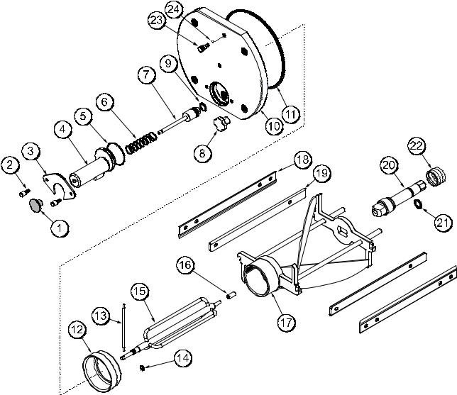
Beater Door Assembly
Item |
Description |
Part No. |
|
|
|
1 |
KNOB-DRAW VALVE-BLACK |
047358 |
|
|
|
2 |
SCREW-1/4-20X9/16 THUMB-300 |
047632 |
|
|
|
3 |
PLATE-DRAW SPOUT MOUNT |
049275 |
|
|
|
4 |
SPOUT-DOOR ZERO WASTE |
049276-BLA |
|
|
|
5 |
O-RING-2.375 OD X 1/16W |
046830 |
|
|
|
6 |
SPRING-COMP.845X.055X3.5 |
047357 |
|
|
|
7 |
VALVE-DRAW |
047353 |
|
|
|
8 |
STUD-NUT (HANDSCREW) |
045644 |
|
|
|
9 |
O-RING-7/8 OD X .103W |
014402 |
|
|
|
10 |
DOOR A.-PARTIAL |
X51098 |
|
|
|
11 |
O-RING-8-3/8 ODX.105W |
027814 |
|
|
|
12 |
BEARING-FRONT-TORQUE |
052005 |
|
|
|
Item |
Description |
Part No. |
|
|
|
13 |
ARM-TORQUE |
014500 |
|
|
|
14 |
O-RING-.291 ID X .080W |
018550 |
|
|
|
15 |
TORQUE A. |
X51081 |
|
|
|
16 |
BEARING-GUIDE |
014496 |
|
|
|
17 |
BEATER A.-TORQUE |
X51105 |
|
|
|
18 |
BLADE-SCRAPER |
051088 |
|
|
|
19 |
CLIP-SCRAPER BLADE |
051978 |
|
|
|
20 |
SHAFT-BEATER |
049270 |
|
|
|
21 |
O-RING-7/8 OD X .139W |
025307 |
|
|
|
22 |
SEAL-DRIVE SHAFT |
032560 |
|
|
|
23 |
PLUG-PRIME *380/1* |
046833 |
|
|
|
24 |
O-RING-9/32 OD X 1/16 WALL |
029751 |
|
|
|
Operator Parts Identification |
8 |
Models 382/RC25 |
 Loading...