


Model 161
Soft Serve Freezer
Operating Instructions
055155-M |
10/02/01 |

Complete this page for quick reference when service is required:
Taylor Distributor:
Address:
Phone:
Service:
Parts:
Date of Installation:
Information found on the data label:
Model Number:
Serial Number:
Electrical Specs: Voltage |
|
Cycle |
|||||
Phase |
|
|
|
|
|
||
Maximum Fuse Size: |
|
|
|
|
A |
||
Minimum Wire Ampacity: |
|
|
|
|
A |
||
E October, 2001 Taylor All rights reserved.
055155--M
The word Taylor and the Crown design
are registered trademarks in the United States of America and certain other countries.
Taylor Company
750 N. Blackhawk Blvd.
Rockton, IL 61072

|
Table of Contents |
|
Section 1 |
To the Installer . . . . . . . . . . . . . . . . . . . . . . . . . . . . . . . . . . . . . . . . . . . . |
1 |
Air Cooled Units . . . . . . . . . . . . . . . . . . . . . . . . . . . . . . . . . . . . . . . . . . . . . . . . . . . . . . . |
1 |
|
Electrical Hook-Up Installation for 60 Cycle, 1 Phase, |
|
|
Supplied With Cord and Plug . . . . . . . . . . . . . . . . . . . . . . . . . . . . . . . . . . . . . . . . . . . |
1 |
|
Electrical Connections for Models Without Cord and Plug Supplied . . . . . . . . . . |
1 |
|
Section 2 |
To the Operator . . . . . . . . . . . . . . . . . . . . . . . . . . . . . . . . . . . . . . . . . . . |
3 |
Compressor Warranty Disclaimer . . . . . . . . . . . . . . . . . . . . . . . . . . . . . . . . . . . . . . . |
3 |
|
Section 3 |
Safety . . . . . . . . . . . . . . . . . . . . . . . . . . . . . . . . . . . . . . . . . . . . . . . . . . . . |
4 |
Section 4 |
Operator Parts Identification . . . . . . . . . . . . . . . . . . . . . . . . . . . . . . . |
5 |
Model 161 . |
. . . . . . . . . . . . . . . . . . . . . . . . . . . . . . . . . . . . . . . . . . . . . . . . . . . . . . . . . . . |
5 |
Beater Door Assembly . . . . . . . . . . . . . . . . . . . . . . . . . . . . . . . . . . . . . . . . . . . . . . . . . |
6 |
|
Accessories |
. . . . . . . . . . . . . . . . . . . . . . . . . . . . . . . . . . . . . . . . . . . . . . . . . . . . . . . . . . |
7 |
Section 5 |
Important: To the Operator . . . . . . . . . . . . . . . . . . . . . . . . . . . . . . . . . |
8 |
Symbol Definitions . . . . . . . . . . . . . . . . . . . . . . . . . . . . . . . . . . . . . . . . . . . . . . . . . . . . |
8 |
|
Softecht Control Machines . . . . . . . . . . . . . . . . . . . . . . . . . . . . . . . . . . . . . . . . . . . . . |
9 |
|
Non--Softecht Control Machines . . . . . . . . . . . . . . . . . . . . . . . . . . . . . . . . . . . . . . . |
11 |
|
Section 6 |
Operating Procedures . . . . . . . . . . . . . . . . . . . . . . . . . . . . . . . . . . . . . |
12 |
Assembly . |
. . . . . . . . . . . . . . . . . . . . . . . . . . . . . . . . . . . . . . . . . . . . . . . . . . . . . . . . . . . |
12 |
Sanitizing . |
. . . . . . . . . . . . . . . . . . . . . . . . . . . . . . . . . . . . . . . . . . . . . . . . . . . . . . . . . . . |
15 |
Priming . . . |
. . . . . . . . . . . . . . . . . . . . . . . . . . . . . . . . . . . . . . . . . . . . . . . . . . . . . . . . . . . |
16 |
Closing Procedure . . . . . . . . . . . . . . . . . . . . . . . . . . . . . . . . . . . . . . . . . . . . . . . . . . . . |
17 |
|
Draining Product From the Freezing Cylinder . . . . . . . . . . . . . . . . . . . . . . . . . . . . . |
18 |
|
Rinsing . . . |
. . . . . . . . . . . . . . . . . . . . . . . . . . . . . . . . . . . . . . . . . . . . . . . . . . . . . . . . . . . |
18 |
Cleaning . . |
. . . . . . . . . . . . . . . . . . . . . . . . . . . . . . . . . . . . . . . . . . . . . . . . . . . . . . . . . . . |
18 |
Disassembly . . . . . . . . . . . . . . . . . . . . . . . . . . . . . . . . . . . . . . . . . . . . . . . . . . . . . . . . . . |
19 |
|
Brush Cleaning . . . . . . . . . . . . . . . . . . . . . . . . . . . . . . . . . . . . . . . . . . . . . . . . . . . . . . . |
19 |
|
Section 7 |
Important: Operator Checklist . . . . . . . . . . . . . . . . . . . . . . . . . . . . . . |
20 |
During Cleaning and Sanitizing . . . . . . . . . . . . . . . . . . . . . . . . . . . . . . . . . . . . . . . . . |
20 |
|
Troubleshooting Bacterial Count . . . . . . . . . . . . . . . . . . . . . . . . . . . . . . . . . . . . . . . . |
20 |
|
Regular Maintenance Checks . . . . . . . . . . . . . . . . . . . . . . . . . . . . . . . . . . . . . . . . . . . |
20 |
|
Winter Storage . . . . . . . . . . . . . . . . . . . . . . . . . . . . . . . . . . . . . . . . . . . . . . . . . . . . . . . . |
21 |
|
Section 8 |
Troubleshooting Guide . . . . . . . . . . . . . . . . . . . . . . . . . . . . . . . . . . . . |
22 |
Section 9 |
Parts Replacement Schedule . . . . . . . . . . . . . . . . . . . . . . . . . . . . . . . |
25 |
Section 10 |
Parts List . . . . . . . . . . . . . . . . . . . . . . . . . . . . . . . . . . . . . . . . . . . . . . . . . |
26 |
Wiring Diagrams . . . . . . . . . . . . . . . . . . . . . . . . . . . . . . . . . . . . . . . . . . . . . . . . . . . . . . |
31 |
|
Note: Continuing research results in steady improvements; therefore, information in this manual is subject to change without notice.
Table of Contents |
Model 161 |
|
|

Notes:
Model 161 |
Table of Contents |
|
|

Section 1 |
To the Installer |
|
|
This machine is designed for indoor use only.
 DO NOT install the machine in an area where a water jet could be used. Failure to follow this instruction may result in serious electrical shock.
Air Cooled Units
The Model 161 requires 6” (152 mm) on both sides, and 0” at the rear. Install the skirt provided on the right side of the unit. Minimum air clearances must be met to assure adequate air flow for optimum performance.
Electrical Hook-Up Installation
(60 Cycle, 1 Ph, Supplied With Cord and Plug)
This freezer is supplied with a 3-wire cord and grounding type plug for connection to a single phase, 60 cycle, branch circuit supply. This unit must be plugged into a properly grounded receptacle. The cord and plug provided for 208/230/60/1, is 20A; therefore the wall outlet must also be 20A. Check the data label, located on the side panel, for electrical specifications.
Permanent wiring may be employed if required by local codes. Instructions for conversion to permanent wiring are as follows:
1.Be sure the freezer is electrically disconnected.
2.Remove the appropriate panel and locate the small electrical box at the base of the freezer.
3.Remove the factory-installed cord and strain relief bushing.
4.Route incoming permanent wiring through 7/8” (22 mm) hole in base pan.
5.Connect two power supply leads. Attach ground (earth) wire to the grounding lug inside the electrical box.
6.Be sure the unit is properly grounded before applying power.
FOLLOW YOUR LOCAL ELECTRICAL CODES!
Electrical Connections
(Models Without Cord and Plug Supplied)
Each freezer requires one power supply for each data label. Check the data label on the freezer for fuse, circuit ampacity and electrical specifications. Refer to the wiring diagram provided inside of the control box, for proper power connections.
In the United States, this equipment is intended to be installed in accordance with the National Electrical Code (NEC), ANSI/NFPA 70--1987. The purpose of the NEC code is the practical safeguarding of persons and property from hazards arising from the use of electricity. This code contains provisions considered necessary for safety. Compliance therewith and proper maintenance will result in an installation essentially free from hazard!
In all other areas of the world, equipment should be installed in accordance with the existing local codes. Please contact your local authorities.
Stationary appliances which are not equipped with a power cord and a plug or other device to disconnect the appliance from the power source must have an all--pole disconnecting device with a contact gap of at least 3 mm installed in the external installation.
 CAUTION: THIS EQUIPMENT MUST BE PROPERLY GROUNDED! Failure to do so can result in severe personal injury from electrical shock.
Beater rotation must be clockwise as viewed looking into the freezing cylinder.
Note: The following procedures should be performed by a trained service technician.
To correct rotation on a three-phase unit, interchange any two incoming power supply lines at freezer main terminal block only. To correct rotation on a single-phase unit, change the leads inside the beater motor. (Follow diagram printed on motor.)
Electrical connections are made directly to the terminal block provided in the splice boxes which are mounted mid-level on the frame channel on the sides of the freezer.
040211
Model 161 |
1 |
To the Installer |
|
|
|

Section 2 |
To the Operator |
|
|
The Model 161 soft serve freezer has been carefully engineered and manufactured to give you dependable operation.
This unit, when properly operated and cared for, will produce a consistent quality product. Like all mechanical products, it will require cleaning and maintenance. A minimum amount of care and attention is necessary if the operating procedures outlined in this manual are followed closely.
This Operator’s Manual should be read before operating or performing any maintenance on your equipment.
The Model 161 will NOT eventually compensate and correct for any errors during the set-up or filling operations. Thus, the initial assembly and priming procedures are of extreme importance. It is strongly recommended that personnel responsible for the equipment’s operation, both assembly and disassembly, go through these procedures together in order to be properly trained and to make sure that no misunderstandings exist.
In the event you should require technical assistance, please contact your local authorized Taylor Distributor.
 If the crossed out wheeled bin symbol is affixed to this product, it signifies that this product is compliant with the EU Directive as well as other similar legislation in effect after August 13, 2005. Therefore, it must be collected separately after its use is completed, and cannot be disposed as unsorted municipal waste.
The user is responsible for returning the product to the appropriate collection facility, as specified by your local code.
For additional information regarding applicable local laws, please contact the municipal facility and/or local distributor.
Compressor Warranty Disclaimer
The refrigeration compressor(s) on this machine are warranted for the term indicated on the warranty card accompanying this machine. However, due to the Montreal Protocol and the U.S. Clean Air Act Amendments of 1990, many new refrigerants are being tested and developed, thus seeking their way into the service industry. Some of these new refrigerants are being advertised as drop-in replacements for numerous applications. It should be noted that, in the event of ordinary service to this machine’s refrigeration system, only the refrigerant specified on the affixed data label should be used. The unauthorized use of alternate refrigerants will void your compressor warranty. It will be the owner’s responsibility to make this fact known to any technician he employs.
It should also be noted that Taylor does not warrant the refrigerant used in its equipment. For example, if the refrigerant is lost during the course of ordinary service to this machine, Taylor has no obligation to either supply or provide its replacement either at billable or unbillable terms. Taylor does have the obligation to recommend a suitable replacement if the original refrigerant is banned, obsoleted, or no longer available during the five year warranty of the compressor.
The Taylor Company will continue to monitor the industry and test new alternates as they are being developed. Should a new alternate prove, through our testing, that it would be accepted as a drop-in replacement, then the above disclaimer would become null and void. To find out the current status of an alternate refrigerant as it relates to your compressor warranty, call the local Taylor Distributor or the Taylor Factory. Be prepared to provide the Model/Serial Number of the unit in question.
050818
To the Operator |
2 |
Model 161 |
|
|
|
Section 3 |
Safety |
|
|
We at Taylor Company are concerned about the safety of the operator when he or she comes in contact with the freezer and its parts. Taylor has gone to extreme efforts to design and manufacture built-in safety features to protect both you and the service technician. As an example, warning labels have been attached to the freezer to further point out safety precautions to the operator.
 IMPORTANT -- Failure to adhere to the following safety precautions may result in severe personal injury. Failure to comply with these warnings may damage the machine and its components. Component damage will result in part replacement expense and service repair expense.
To Operate Safely:
 DO NOT operate the freezer without reading this operator’s manual. Failure to follow this instruction may result in equipment damage, poor freezer performance, health hazards, or personal injury.
SDO NOT operate the freezer unless it is properly grounded.
SDO NOT operate the freezer with larger fuses than specified on the freezer data label.
SDO NOT attempt any repairs unless the main power supply to the freezer has been disconnected.
Failure to follow these instructions may result in electrocution. Contact your local authorized Taylor Distributor for service.
 DO NOT use a water jet to clean or rinse the freezer. Failure to follow these instructions may result in serious electrical shock.
SDO NOT allow untrained personnel to operate this machine.
SDO NOT put objects or fingers in door spout.
SDO NOT operate the freezer unless all service panels and access doors are restrained with screws.
SDO NOT remove the freezer door or beater assembly unless the control switches are in the “OFF” position.
Failure to follow these instructions may result in severe personal injury from hazardous moving parts.
 USE EXTREME CAUTION when removing the beater assembly. The scraper blades are very sharp and may cause injury.
 This freezer must be placed on a level surface. Failure to comply may result in personal injury or equipment damage.
DO NOT obstruct air intake and discharge openings: A minimum of 6” (152 mm) on both sides, and 0” in the rear is required. Install the skirt provided on the right side of the unit. Failure to follow this instruction may cause poor freezer performance and damage to the machine.
This freezer is designed to operate indoors, under normal ambient temperatures of 70_--75_F (21_--24_C). The freezer has successfully performed in high ambient temperatures of 104_F (40_C) at reduced capacity.
NOISE LEVEL: Airborne noise emission does not exceed 78 dB(A) when measured at a distance of 1.0 meter from the surface of the machine and at a height of 1.6 meters from the floor.
040211
Model 161 |
3 |
Safety |
|
|
|

Section 4 Operator Parts Identification
Model 161
ITEM |
DESCRIPTION |
PART NO. |
|
|
|
1 |
PANEL-REAR *161* |
055129 |
2 |
PANEL-SIDE-RIGHT *161* |
055130 |
|
|
|
3 |
LEG-4” 3/8-16 STUD |
036397 |
|
|
|
4 |
CAP-RUBBER |
037268 |
|
|
|
5 |
SHIELD-SPLASH |
022765 |
|
|
|
6 |
TRAY-DRIP 16-7/8L X 5-1/8 |
020157 |
|
|
|
7 |
PANEL-LOWER FRONT *161* |
055513 |
|
|
|
8 |
PAN-DRIP *161* |
055206 |
|
|
|
ITEM |
DESCRIPTION |
PART NO. |
|
|
|
9 |
PANEL A.-SIDE LEFT *161* |
X55122 |
10 |
GASKET-HOPPER COVER |
037042 |
|
|
|
11 |
KNOB-MIX COVER |
025429 |
|
|
|
12 |
COVER A.-HOPPER |
X37963-SER |
|
|
|
13 |
PANEL A.-FRONT *161* |
X55203 |
|
|
|
14 |
TUBE--FEED |
030797 |
|
|
|
15 |
COLLAR--MIX PROBE |
031628 |
|
|
|
Operator Parts Identification |
4 |
Model 161 |
|
|
|
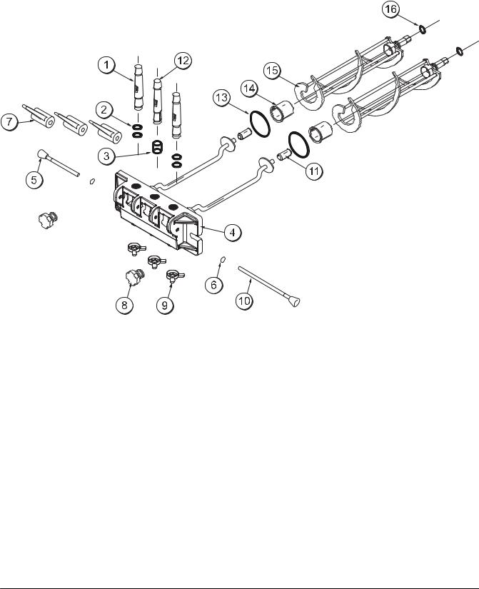
Beater Door Assembly
ITEM |
DESCRIPTION |
PART NO. |
|
|
|
1 |
DRAW VALVE |
024763 |
|
|
|
2 |
O--RING 7/8 OD X .103 W |
014402 |
|
|
|
3 |
SEAL--VALVE |
030930 |
|
|
|
4 |
DOOR A.--3 SPOUT |
X30753--SER |
|
|
|
5 |
PIVOT PIN A.--SHORT |
X38539 |
|
|
|
6 |
O--RING 5/16 OD X .070 W |
016272 |
|
|
|
7 |
DRAW VALVE HANDLE |
030564 |
|
|
|
8 |
HAND SCREW (STUD NUT) |
034829 |
|
|
|
ITEM |
DESCRIPTION |
PART NO. |
|
|
|
9 |
DESIGN CAP |
014218 |
|
|
|
10 |
PIVOT PIN A.--LONG |
X38538 |
|
|
|
11 |
GUIDE BEARING |
014496 |
|
|
|
12 |
CENTER DRAW VALVE |
031164 |
|
|
|
13 |
O--RING 2--3/4 OD X .139 W |
019998 |
|
|
|
14 |
FRONT BEARING |
023262 |
|
|
|
15 |
BEATER ASSEMBLY |
X24689 |
|
|
|
16 |
O--RING--13/16 OD X .139 W |
021278 |
|
|
|
Model 161 |
5 |
Operator Parts Identification |
|
|
|
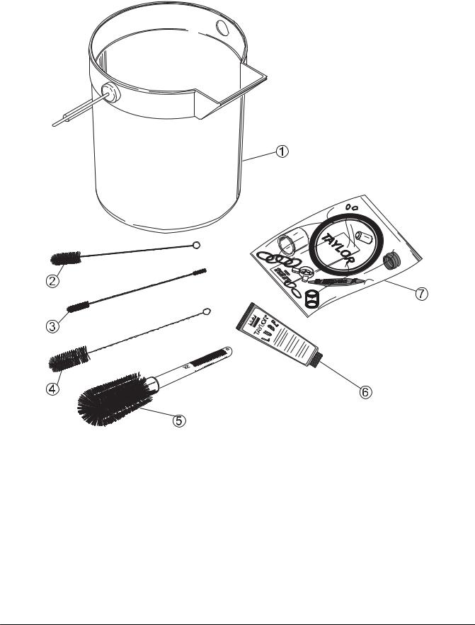
Accessories
ITEM |
DESCRIPTION |
PART NO. |
|
|
|
1 |
PAIL-6·QT. |
023348 |
|
|
|
2 |
BRUSH-REAR BRG 1” D X 2” LG |
013071 |
|
|
|
3 |
BRUSH-DOUBLE·ENDED |
013072 |
|
|
|
4 |
BRUSH-DRAW·VALVE·1” OD X |
013073 |
|
2” X 17” |
|
ITEM |
DESCRIPTION |
PART NO. |
|
|
|
5 |
BRUSH-MIX·PUMP·BODY-3”X7” |
023316 |
|
WHITE |
|
6 |
LUBRICANT-TAYLOR·4·OZ. |
047518 |
|
|
|
7 |
KIT·A.-TUNE·UP |
X31167 |
|
|
|
* |
SANITIZER KAY-5 125 PKTS |
041082 |
|
|
|
*NOT SHOWN
Operator Parts Identification |
6 |
Model 161 |
|
|
|
Section 5 |
|
|
|
|
|
Important: To the Operator |
||||||||||||||
|
|
|
|
|
|
|
|
|
|
|
|
|
|
|
|
|
|
|
|
|
|
|
|
|
|
|
|
|
|
|
|
|
|
|
|
|
|
|
|
|
|
|
|
|
|
|
|
|
|
|
|
|
|
|
|
|
|
|
|
|
|
|
|
|
|
|
|
|
|
|
|
|
|
|
|
|
|
|
|
|
|
|
|
|
|
|
|
|
|
|
|
|
|
|
|
|
|
|
|
|
|
|
|
|
|
|
|
|
|
|
|
|
|
|
|
|
|
|
|
|
|
|
|
|
|
|
|
|
|
|
|
|
|
|
|
|
|
|
|
|
|
|
|
|
|
|
ITEM |
DESCRIPTION |
|
|
1 |
POWER SWITCH |
2 |
MIX REFRIGERATION KEY |
|
|
3 |
STANDBY KEY |
|
|
4 |
WASH KEY |
|
|
5 |
AUTO KEY |
|
|
6 |
INDICATOR LIGHT “MIX LOW” |
|
|
7 |
RESET BUTTON |
|
|
Symbol Definitions
To better communicate in the International arena, the words on many of our operator switches and keys have symbols to indicate their functions. Your Taylor equipment is designed with these International symbols.
The following chart identifies the symbol definitions used on the operator switches.
= OFF
= ON
= MIX
= STANDBY
= WASH
= AUTO
= MIX LOW
Model 161 |
7 |
Important: To the Operator |
|
|
|
 Loading...