


 Loading...
D00539600A
DA-98HR
Digital Multitrack Recorder
OWNER’S MANUAL
ÜREMOVE COVER (OR BACK). NO USER-SERVICEABLE PARTS INSIDE. REFER SERVICING TO QUALIFIED SERVICE PERSONNEL.CAUTION: TO REDUCE THE RISK OF ELECTRIC SHOCK, DO NOT
ÿthe user to the presence of uninsulated “dangerous voltage” within the product’s enclosure that may be of sufficient magnitude to constitute a risk of electric shock to persons.The lightning flash with arrowhead symbol, within an equilateral triangle, is intended to alert
Ÿence of important operating and maintenance (servicing) instructions in the literature accompanying the appliance.The exclamation point within an equilateral triangle is intended to alert the user to the pres-
This appliance has a serial number located on the rear panel. Please record the model number and serial number and retain them for your records.
Model number Serial number
WARNING: TO PREVENT FIRE OR SHOCK HAZARD, DO NOT EXPOSE THIS APPLIANCE TO RAIN OR MOISTURE.

Important Safety Precautions
IMPORTANT (for U.K. Customers)
DO NOT cut off the mains plug from this equipment.
If the plug fitted is not suitable for the power points in your home or the cable is too short to reach a power point, then obtain an appropriate safety approved extension lead or consult your dealer.
If nonetheless the mains plug is cut off, remove the fuse and dispose of the plug immediately, to avoid
a possible shock hazard by inadvertent connection to the mains supply.
If this product is not provided with a mains plug, or one has to be fitted, then follow the instructions given below:
IMPORTANT: The wires in this mains lead are coloured in accordance with the following code:
GREEN-AND-YELLOW : EARTH
BLUE |
: |
NEUTRAL |
BROWN |
: |
LIVE |
WARNING: This apparatus must be earthed.
As the colours of the wires in the mains lead of this apparatus may not correspond with the coloured markings identifying the terminals in your plug proceed as follows:
The wire which is coloured GREEN-and-YELLOW must be connected to the terminal in the plug which is marked by the letter E or by the safety earth symbol çor coloured GREEN or GREEN- and-YELLOW.
The wire which is coloured BLUE must be connected to the terminal which is marked with the letter N or coloured BLACK.
The wire which is coloured BROWN must be connected to the terminal which is marked with the letter L or coloured RED.
When replacing the fuse only a correctly rated approved type should be used and be sure to re-fit the fuse cover.
IF IN DOUBT — CONSULT A COMPETENT ELECTRICIAN.
For U.S.A
TO THE USER
This equipment has been tested and found to comply with the limits for a Class A digital device, pursuant to Part 15 of the FCC Rules. These limits are designed to provide reasonable protection against harmful interference when the equipment is operated in a commercial environment. This equipment generates, uses, and can radiate radio frequency energy and, if not installed and used in accordance with the instruction manual, may cause harmful interference to radio communications.
Operation of this equipment in a residental area is likely to cause harmful interference in which case the user will be required to correct the interference at his own expense.
CAUTION
Changes or modifications to this equipment not expressly approved by TEAC CORPORATION for compliance could void the user’s authority to operate this equipment.
For the consumers in Europe
WARNING
This is a Class A product. In a domestic environment, this product may cause radio interference in which case the user may be required to take adequate measures.
Pour les utilisateurs en Europe
AVERTISSEMENT
Il s’agit d’un produit de Classe A. Dans un environnement domestique, cet appareil peut provoquer des interférences radio, dans ce cas l’utilisateur peut être amené à prendre des mesures appropriées.
Für Kunden in Europa
Warnung
Dies is eine Einrichtung, welche die Funk-Entstörung nach Klasse A besitzt. Diese Einrichtung kann im Wohnbereich Funkstörungen versursachen ; in diesem Fall kann vom Betrieber verlang werden, angemessene Maßnahmen durchzuführen und dafür aufzukommen.
2 TASCAM DA-98HR
IMPORTANT SAFETY INSTRUCTIONS
CAUTION:
…Read all of these Instructions.
…Save these Instructions for later use.
…Follow all Warnings and Instructions marked on the audio equipment.
1)Read Instructions — All the safety and operating instructions should be read before the product is operated.
2)Retain Instructions — The safety and operating instructions should be retained for future reference.
3)Heed Warnings — All warnings on the product and in the operating instructions should be adhered to.
4)Follow Instructions — All operating and use instructions should be followed.
5)Cleaning — Unplug this product from the wall outlet before cleaning. Do not use liquid cleaners or aerosol cleaners. Use a damp cloth for cleaning.
6)Attachments — Do not use attachments not recommended by the product manufacturer as they may cause hazards.
7)Water and Moisture — Do not use this product near water — for example, near a bath tub, wash bowl, kitchen sink, or laundry tub; in a wet basement; or near a swimming pool; and the like.
8)Accessories — Do not place this product on an unstable cart, stand, tripod, bracket, or table. The product may fall, causing serious injury to a child or adult, and serious damage to the product. Use only with a cart, stand, tripod, bracket, or table recommended by the manufacturer, or sold with the product. Any mounting of the product should follow the manufacturer’s instructions, and should use a mounting accessory recommended by the manufacturer.
9)A product and cart combination should be moved with care. Quick stops, excessive force, and uneven surfaces may cause the product and cart combination to overturn.
10)Ventilation — Slots and openings in the cabinet are provided for ventilation and to ensure reliable operation of the product and to protect it from overheating, and these openings must not be blocked or covered. The openings should never be blocked by placing the product on a bed, sofa, rug, or other similar surface. This product should not be placed in a built-in installation such as a bookcase or rack unless proper ventilation is provided or the manufacturer’s instructions have been adhered to.
11)Power Sources — This product should be operated only from the type of power source indicated on the marking label. If you are not sure of the type of power supply to your home, consult your product dealer or local power company. For products intended to operate from battery power, or other sources, refer to the operating instructions.
12)Grounding or Polarization — This product may be equipped with a polarized alternating-current line plug (a plug having one blade wider than the other). This plug will fit into the power outlet only one way. This is a safety feature. If you are unable to insert the plug fully into the outlet, try reversing the plug. If the plug should still fail to fit, contact your electrician to replace your obsolete outlet. Do not defeat the safety purpose of the polarized plug.
13)Power-Cord Protection — Power-supply cords should be routed so that they are not likely to be walked on or pinched by items placed upon or against them, paying particular attention to cords at plugs, convenience receptacles, and the point where they exit from the product.
14)Outdoor Antenna Grounding — If an outside antenna or cable system is connected to the product, be sure the antenna or cable system is grounded so as to provide some protection against voltage surges and builtup static charges. Article 810 of the National Electrical Code, ANSI/NFPA 70, provides information with regard to proper grounding of the mast and supporting structure, grounding of the lead-in wire to an antenna discharge unit, size of grounding conductors, location of antenna-discharge unit, connection to grounding electrodes, and requirements for the grounding electrode.
"Note to CATV system installer:
This reminder is provided to call the CATV system installer’s attention to Section 820-40 of the NEC which provides guidelines for proper grounding and, in particular, specifies that the cable ground shall be connected to the grounding system of the building, as close to the point of cable entry as practical.
Example of Antenna Grounding as per
National Electrical Code, ANSI/NFPA 70
|
ANTENNA |
|
LEAD IN |
|
WIRE |
|
GROUND |
|
CLAMP |
|
ANTENNA |
|
DISCHARGE UNIT |
|
(NEC SECTION 810-20) |
ELECTRIC |
|
SERVICE |
GROUNDING CONDUCTORS |
EQUIPMENT |
|
|
(NEC SECTION 810-21) |
|
GROUND CLAMPS |
|
POWER SERVICE GROUNDING |
|
ELECTRODE SYSTEM |
NEC - NATIONAL ELECTRICAL CODE |
(NEC ART 250. PART H) |
|
15)Lightning — For added protection for this product during a lightning storm, or when it is left unattended and unused for long periods of time, unplug it from the wall outlet and disconnect the antenna or cable system. This will prevent damage to the product due to lightning and power-line surges.
16)Power Lines — An outside antenna system should not be located in the vicinity of overhead power lines or other electric light or power circuits, or where it can fall into such power lines or circuits. When installing an outside antenna system, extreme care should be taken to keep from touching such power lines or circuits as contact with them might be fatal.
17)Overloading — Do not overload wall outlets, extension cords, or integral convenience receptacles as this can result in risk of fire or electric shock.
18)Object and Liquid Entry — Never push objects of any kind into this product through openings as they may touch dangerous voltage points or short-out parts that could result in a fire or electric shock. Never spill liquid of any kind on the product.
19)Servicing — Do not attempt to service this product yourself as opening or removing covers may expose you to dangerous voltage or other hazards. Refer all servicing to qualified service personnel.
20)Damage Requiring Service — Unplug this product from the wall outlet and refer servicing to qualified service personnel under the following conditions:
a) when the power-supply cord or plug is damaged.
b) if liquid has been spilled, or objects have fallen into the product. c) if the product has been exposed to rain or water.
d) if the product does not operate normally by following the operating instructions. Adjust only those controls that are covered by the operating instructions as an improper adjustment of other controls may result in damage and will often require extensive work by a qualified technician to restore the product to its normal operation.
e) if the product has been dropped or damaged in any way.
f ) when the product exhibits a distinct change in performance – this indicates a need for service.
21)Replacement Parts — When replacement parts are required, be sure the service technician has used replacement parts specified by the manufacturer or have the same characteristics as the original part.
Unauthorized substitutions may result in fire, electric shock, or other hazards.
22)Safety Check — Upon completion of any service or repairs to this product, ask the service technician to perform safety checks to determine that the product is in proper operating condition.
23)Wall or Ceiling Mounting — The product should be mounted to a wall or ceiling only as recommended by the manufacturer.
24)Heat — The product should be situated away from heat sources such as radiators, heat registers, stoves, or other products (including amplifiers) that produce heat.
TASCAM DA-98HR 3

Table of Contents |
|
1 – Introduction to the DA-98HR |
|
1.1 Unpacking ..................................................... |
7 |
1.2 Features......................................................... |
7 |
1.3 Using this manual......................................... |
8 |
1.3.1 How this manual is organized....................... |
8 |
1.3.2 Typographic conventions ............................. |
8 |
1.4 Notes and precautions ................................. |
8 |
1.4.1 Clock source in a digital studio .................... |
9 |
1.4.2 Confidence replay .......................................... |
9 |
1.4.3 Environmental conditions ............................. |
9 |
1.4.4 Installing the DA-98HR .................................. |
9 |
1.4.5 Electrical considerations............................... |
9 |
1.4.6 Condensation ................................................. |
10 |
1.5 Recommended tapes.................................... |
10 |
1.5.1 Tape brands.................................................... |
11 |
1.5.2 Available recording and playback time........ |
11 |
2 – Front and rear panels |
|
2.1 Front Panel controls..................................... |
12 |
2.2 Rear Panel connectors................................. |
17 |
3 – Connections |
|
3.1 Audio connection ......................................... |
19 |
3.1.1 Analog audio connections (optional |
|
IF-AN98HR)........................................................... |
19 |
3.1.2 Digital audio connections (using TDIF-1) .... |
19 |
3.1.3 Digital audio connections (using AES/EBU)19 |
|
3.2 Synchronization connections...................... |
20 |
3.2.1 Analog timecode connections ...................... |
20 |
3.2.2 Video connections ......................................... |
20 |
3.2.3 Word sync clock connections ...................... |
20 |
3.3 Control connections..................................... |
21 |
3.3.1 RS-422 connector........................................... |
21 |
3.3.2 MIDI connectors (IN , OUT and THRU) ......... |
21 |
3.3.3 Parallel control ............................................... |
21 |
3.4 Connection to other TASCAM units............ |
21 |
3.4.1 Multiple DTRS units ....................................... |
21 |
3.4.2 “Indirect” word sync...................................... |
21 |
3.4.3 Meter unit (MU-8824)...................................... |
22 |
4 – Menu operations |
|
4.1 The menus..................................................... |
23 |
4.1.1 Navigation around the menu system ........... |
23 |
4.1.2 Using the ENTER key..................................... |
23 |
4.1.3 The ESCAPE key ............................................ |
23 |
4.1.4 Editing values................................................. |
23 |
4.1.5 Resetting a menu value ................................. |
24 |
4.1.6 Changing menu values fast .......................... |
24 |
4.1.7 Using the dial to change values ................... |
24 |
4.1.8 Blanking the screen display.......................... |
24 |
4.2 About the function keys............................... |
24 |
4.2.1 Function key modes ...................................... |
24 |
4.2.2 The SHIFT key and function keys................. |
25 |
4.3 Assigning menus to function keys ............. |
25 |
4.3.1 To assign a menu screen to a key................ |
25 |
4.3.2 Recalling an assigned menu function.......... |
25 |
4.4 Using the function keys as number keys... |
25 |
5 – Monitoring modes |
|
5.1 Monitoring controls...................................... |
27 |
5.1.1 ALL INPUT and INPUT MONITOR ................. |
27 |
5.1.2 AUTO MON...................................................... |
27 |
5.1.3 Shuttle monitoring ......................................... |
27 |
5.2 Patching the outputs.................................... |
28 |
5.3 Confidence mode ......................................... |
28 |
5.3.1 Arming tracks in pairs ................................... |
29 |
5.3.2 Using confidence mode................................. |
29 |
5.4 Mixdown patchbay ....................................... |
29 |
5.4.1 Turning on the MIXDOWN mode................... |
29 |
5.4.2 Selecting the mixdown sources ................... |
30 |
5.4.3 Setting mixdown levels ................................. |
30 |
6 – Basic Operations |
|
6.1 Word sync settings ...................................... |
31 |
6.1.1 Selecting the word sync clock...................... |
31 |
6.1.2 Setting the AES/EBU channel for the |
|
word sync source................................................ |
31 |
6.1.3 Clock range with slot board.......................... |
31 |
6.2 Formatting a tape ......................................... |
32 |
6.2.1 Available tracks.............................................. |
32 |
6.2.2 The format process........................................ |
32 |
6.2.3 Aborting the format process......................... |
33 |
6.2.4 Recording while formatting........................... |
33 |
6.3 Recording the first tracks ............................ |
33 |
6.3.1 Preparing to record........................................ |
34 |
6.3.2 Selecting the digital source .......................... |
34 |
6.3.3 Selecting input sources................................. |
34 |
6.3.4 Write-protecting cassettes............................ |
34 |
6.3.5 Recording the basic tracks (i)....................... |
34 |
6.3.6 Recording the basic tracks (ii)...................... |
35 |
6.3.7 Replaying the first tracks .............................. |
35 |
6.4 Overdubbing ................................................. |
35 |
6.5 Track bouncing............................................. |
35 |
6.6 Punch-in and punch-out .............................. |
35 |
6.6.1 Overview of punch procedures .................... |
36 |
6.6.2 Automatic punch point setting ..................... |
36 |
6.6.3 Setting punch points “on the fly”................. |
36 |
6.6.4 Setting and editing punch points using the |
|
menus................................................................... |
37 |
6.6.5 Editing the preroll and postroll times .......... |
37 |
6.6.6 Rehearsing the punch-in............................... |
38 |
6.6.7 Interrupting a rehearsal or punch recording38 |
|
6.6.8 Recording the punch-in................................. |
38 |
6.6.9 Reviewing the punched material .................. |
39 |
6.6.10 Exiting punch-in mode ................................ |
39 |
7 – Advanced operations |
|
7.1 Autolocation.................................................. |
40 |
7.1.1 Setting MEMO 1 and MEMO 2 “on the fly”...40
4 TASCAM DA-98HR

7.1.2 Checking, editing and manually entering |
|
MEMO 1 and MEMO 2.......................................... |
40 |
7.1.3 Setting the location pre-roll time .................. |
40 |
7.1.4 Locating to MEMO 1 and MEMO 2 ................ |
41 |
7.2 Function key location memories ................ |
41 |
7.2.1 Storing a function key location memory...... |
41 |
7.2.2 Editing function key memories..................... |
41 |
7.2.3 Locating to a function key memory.............. |
41 |
7.2.4 Location and playback .................................. |
42 |
7.2.5 Repeat function .............................................. |
42 |
7.2.6 To start repeat play ........................................ |
42 |
7.3 Track delay.................................................... |
42 |
7.3.1 To set the track delay: ................................... |
43 |
7.4 Crossfade time ............................................. |
43 |
7.5 Vari speed (pitch control) ............................ |
43 |
7.5.1 To set a non-standard speed ........................ |
43 |
7.5.2 Resetting the speed to standard .................. |
44 |
7.6 Shuttle operations........................................ |
44 |
7.6.1 Shuttle monitoring ......................................... |
44 |
7.6.2 Shuttle muting ................................................ |
45 |
7.7 Reference levels........................................... |
45 |
7.8 Meter modes ................................................. |
45 |
7.8.1 Peak hold time................................................ |
45 |
7.8.2 Meter ballistics ............................................... |
45 |
7.9 Sine oscillator............................................... |
46 |
7.9.1 Recording the oscillator ................................ |
46 |
7.10 Digital recording......................................... |
46 |
7.10.1 Selecting different inputs for recording..... |
46 |
7.10.2 Selecting input word length ........................ |
46 |
7.10.3 Setting the high-frequency AES/EBU I/O |
|
transfer mode....................................................... |
47 |
7.10.4 Cbit mode...................................................... |
47 |
7.11 REC MUTE (recording silence) ................. |
47 |
7.11.1 Viewing user bits.......................................... |
47 |
7.12 Dither........................................................... |
48 |
7.12.1 Selecting dither settings ............................. |
48 |
7.13 Output word length .................................... |
48 |
7.14 Disabling automatic muting ...................... |
48 |
7.15 Setting the power-on message ................. |
49 |
8 – DTRS synchronization |
|
8.1 Synchronization connections ..................... |
50 |
8.2 Machine ID and master/slave settings ....... |
50 |
8.2.1 Differences between DTRS models.............. |
50 |
8.2.2 Setting machine ID......................................... |
51 |
8.2.3 Master/slave settings (CHASE mode) .......... |
51 |
8.3 DTRS emulation............................................ |
51 |
8.4 Machine offset .............................................. |
52 |
8.4.1 Setting machine offset................................... |
52 |
8.4.2 Cancelling machine offset............................. |
52 |
8.4.3 Setting machine offset “on the fly” .............. |
52 |
8.4.4 An example of setting offsets ....................... |
52 |
8.4.5 Clock mode..................................................... |
53 |
Table of Contents |
|
8.5 Digital dubbing .............................................. |
54 |
8.5.1 Synchronized formatting............................... |
54 |
8.5.2 Recording while formatting........................... |
55 |
8.6 Error messages ............................................. |
55 |
9 – Operations related to timecode |
|
9.1 ABS and SMPTE/EBU timecode .................. |
56 |
9.1.1 ABS time ......................................................... |
56 |
9.1.2 Tape timecode................................................ |
56 |
9.1.3 Selecting TC or ABS timing .......................... |
56 |
9.2 Tape timecode mode .................................... |
57 |
9.2.1 TcTrack setting .............................................. |
57 |
9.2.2 ABS setting..................................................... |
57 |
9.2.3 ABS-Ofs setting ............................................. |
57 |
9.2.4 ABS-13 and ABS-23 settings ........................ |
57 |
9.2.5 Checking tape TC........................................... |
58 |
9.3 Recording timecode...................................... |
58 |
9.3.1 Selecting the timecode source ..................... |
58 |
9.3.2 Recording timecode using the generator.... |
59 |
9.3.3 Recording synthesized timecode from |
|
ABS timing ........................................................... |
60 |
9.3.4 Assembling timecode.................................... |
60 |
9.3.5 External timecode sources ........................... |
60 |
9.3.6 Recording timecode from an analog |
|
recorder................................................................ |
61 |
9.3.7 Recording timecode from external |
|
sources................................................................. |
61 |
9.3.8 Checking external timecode ......................... |
62 |
9.4 Selecting the frame rate ............................... |
62 |
9.4.1 Pull up and pull down (Fs shift).................... |
62 |
9.5 Timecode input and output .......................... |
62 |
9.5.1 Timecode input .............................................. |
63 |
9.5.2 Timecode output ............................................ |
63 |
9.5.3 Timecode output format................................ |
63 |
9.5.4 Timecode input and output timing ............... |
63 |
9.5.5 Using MIDI Time Code (MTC)........................ |
64 |
9.6 Chasing to timecode..................................... |
64 |
9.6.1 Machine ID and timecode.............................. |
64 |
9.6.2 Setting timecode offset ................................. |
64 |
9.6.3 Setting timecode offset from the menu ....... |
65 |
9.6.4 Cancelling timecode offset ........................... |
65 |
9.6.5 Setting timecode offset on-the-fly................ |
65 |
9.6.6 Timecode accuracy........................................ |
65 |
9.6.7 Park position .................................................. |
65 |
9.6.8 Automatic park position setting ................... |
65 |
9.6.9 Absolute and relative difference................... |
66 |
9.6.10 Rechasing timecode .................................... |
66 |
9.6.11 Bypassing timecode errors......................... |
67 |
9.6.12 Individual recording while chasing |
|
timecode............................................................... |
67 |
9.7 Video resolution ............................................ |
67 |
9.7.1 Video reference setting ................................. |
68 |
10 – External control |
|
10.1 Selecting the control source (protocol) .... |
69 |
TASCAM DA-98HR 5

Table of Contents |
|
10.2 Disabling local control ............................... |
69 |
10.3 Use with 9-pin external control ................. |
69 |
10.3.1 Video clocking.............................................. |
69 |
10.3.2 Emulation...................................................... |
69 |
10.3.3 Record delay................................................. |
70 |
10.3.4 Cue-up tally................................................... |
70 |
10.3.5 Fast wind speed ........................................... |
70 |
10.3.6 Track mapping.............................................. |
71 |
10.3.7 Timecode track mapping............................. |
71 |
10.3.8 Remote track arming ................................... |
72 |
10.4 Bus protocol................................................ |
72 |
10.4.1 Assigning a MIDI and Bus ID to the |
|
DA-98HR ............................................................... |
72 |
10.5 MIDI Machine Control ................................. |
72 |
10.5.1 MMC and the DA-98HR ................................ |
72 |
11 – Menu and parameter reference |
|
11.1 Menu groups ............................................... |
74 |
11.1.1 Menu group 0................................................ |
74 |
11.1.2 Menu group 1................................................ |
74 |
11.1.3 Menu group 2................................................ |
75 |
11.1.4 Menu group 3................................................ |
75 |
11.1.5 Menu group 4................................................ |
76 |
11.1.6 Menu group 5................................................ |
76 |
11.1.7 Menu group 6................................................ |
77 |
11.1.8 Menu group 7................................................ |
77 |
11.1.9 Menu group 8................................................ |
78 |
11.1.10 Menu group 9.............................................. |
78 |
11.1.11 Menu group A ............................................. |
79 |
11.1.12 Menu group B ............................................. |
79 |
11.1.13 Menu group D ............................................. |
80 |
11.1.14 Menu group E ............................................. |
80 |
11.1.15 Menu group F ............................................. |
80 |
11.2 Menu item index.......................................... |
81 |
12 – Maintenance and settings |
|
12.1 Head and transport cleaning ..................... |
83 |
12.1.1 Daily cleaning ............................................... |
83 |
12.1.2 Periodic cleaning ......................................... |
83 |
12.2 Checking error rates................................... |
84 |
12.2.1 Checking head time ..................................... |
84 |
12.2.2 Checking head search time......................... |
84 |
12.3 Memory backup .......................................... |
84 |
12.4 User setups in RAM.................................... |
85 |
12.4.1 Saving user setups ...................................... |
85 |
12.4.2 Loading user setups.................................... |
85 |
12.4.3 Resetting the memory to factory defaults .85 |
|
12.5 Tape storage of settings ............................ |
86 |
12.5.1 Saving settings to tape................................ |
86 |
12.5.2 Loading settings from tape......................... |
86 |
12.6 Checking version numbers ....................... |
86 |
12.6.1 Software upgrades....................................... |
87 |
13 – Options/specifications/reference |
|
13.1 DA-98HR options ........................................ |
88 |
13.1.1 Accuride® mounting.................................... |
88 |
13.1.2 Remote control units (RC-898, RC-848 |
|
and RC-828) ......................................................... |
88 |
13.1.3 Meter unit (MU-8824).................................... |
88 |
13.1.4 Cables ........................................................... |
88 |
13.2 Specifications ............................................. |
89 |
13.2.1 Physical specifications................................ |
89 |
13.2.2 Power specifications ................................... |
89 |
13.2.3 Digital recording characteristics ................ |
89 |
13.2.4 Tape recorder section.................................. |
89 |
13.2.5 Tape transport.............................................. |
89 |
13.2.6 Inputs and outputs....................................... |
89 |
13.2.7 Recorder chaacteristics .............................. |
90 |
13.2.8 9-pin (RS-422), MIDI, synchronizer |
|
specifications ...................................................... |
90 |
13.3 MMC Bit Map Array..................................... |
91 |
13.4 MIDI Implementation Chart ........................ |
93 |
13.5 MIDI Control Change .................................. |
94 |
13.6 MIDI System Exclusive............................... |
94 |
13.6.1 Identity Reply................................................ |
94 |
13.6.2 TASCAM Exclusive messages.................... |
94 |
13.6.3 Track delay ................................................... |
94 |
13.6.4 Crossfade ..................................................... |
94 |
13.6.5 Machine offset.............................................. |
94 |
13.6.6 Input Patch setup......................................... |
95 |
6 TASCAM DA-98HR

1 – Introduction to the DA-98HR
The TASCAM DA-98HR is a digital audio multitrack recorder designed for use in a variety of applications, including video post-production and audio multitrack work.
It records up to 8 tracks of full-quality digital audio on standard Hi8 video cassettes using a speciallydesigned transport and head mechanism. Using this medium, up to 108 minutes of continuous recording is possible on a single NTSC “120” tape.
Recording is carried out at either 24 bits or 16 bits of resolution, and digital data may be input at 16, 20 or 24 bits of resolution.
As well as the “traditional” industry-standard
44.1 kHz and 48 kHz sampling frequencies, the DA98HR can also record and playback at double and four times these sampling frequencies: 88.2 kHz and 176.4 kHz, and 96 kHz and 192 kHz.
The DA-98HR builds on the foundations laid by the TASCAM DA-78HR, DA98, DA-88 and DA-38 digital multitrack recorders, and retains compatibility with them. Tapes recorded on one of the DTRS series can be replayed and overdubbed on any other machine in the series, or any DTRS1 machine, subject to the word length and sampling frequency capabilities of both machines.
NOTE
Recording is an art as well as a science. A successful recording is often judged primarily on the quality of sound as art, and we obviously cannot guarantee that. A company that makes paint and brushes for artists cannot say that the paintings made with their products will be critically well-received. TASCAM can make no guarantee that the DA-98HR by itself will assure the quality of the recordings you make. Your skill as a technician and your abilities as an artist will be significant factors in the results you achieve.
1.1Unpacking
The box contains the following.
•DA-98HR Digital Multitrack Recorder (x 1)
•Rackmount screw kit (x 1)
•AC power cord, 2 m (6 ft.) long (x 1)
•This manual (x 1)
•Warranty card (x 1)
•Quick Start guide (x 1)
•HC-8 cleaning tape
1.DTRS is a trademark of TEAC Corporation
1.2Features
Key features of the DA-98HR include:
•TASCAM-exclusive high-performance/high wear resistive rotary 4-head mechanism with TASCAM original track layout (DTRS standard)
•Use of standard, low-cost media with long recording and playback times
•16-bit or 24-bit recording
•“Traditional” and high-speed sampling rates for ultimate sonic performance
•Different sampling frequencies can be recorded simultaneously on different tracks on the same tape, providing ultimate flexibility
•Fast, frame-accurate tape location and positioning; end-to-end winding for a “120” tape is around 80 seconds
•Direct digital synchronization of up to 16 DTRS recorders (128 tracks) without the use of any external synchronizer or controller
•Direct digital dubbing between DTRS units
•Input patchbay provides an internal digital patchbay, allowing input-to-track assignment without the use of external equipment
•Output patchbay allows the routing of tracks to outputs without the need for external equipment
•15-segment peak meters with user-selectable fall ballistics and variable hold time (including continuous peak hold)
•Integral digital sine oscillator, providing signals at 440Hz for tuning and 1kHz for lineup purposes
•Digital input and output in TDIF-1 format on a single convenient compact D-sub connector
•Eight channels of AES/EBU I/O on a single convenient compact D-sub connector
•Two expansion slots allow the use of optional accessory boards, such as analog I/O, optimized for use with the DA-98HR
•Settings carried out through a menu hierarchy using a 20-character x 4-line LCD display with cursor keys and an ENTER/ESCAPE system
•The 10 most commonly-used functions can be assigned to “soft keys” for easy recall
•Full SMPTE/EBU timecode synchronization , including on-board timecode generator
•MIDI Time Code and MIDI Machine Control
•Confidence replay mode, allowing off-tape monitoring while recording is in progress
TASCAM DA-98HR 7

1 – Introduction to the DA-98HR–Using this manual
•Input monitor mode allows channel-by-channel source monitoring, regardless of tape transport status
•Three user setup memory banks for storing setup profiles
•Simplified source/tape monitoring functions with automatic switching
•Auto punch-in and punch-out with rehearsal mode
•2-point full function autolocator with A–B repeat function , and 10 “soft key” location memories
•Variable speed recording and playback (up to 6.0% in 0.1% steps)
•Shuttle mode enables “rock and roll” audio positioning of key locations
1.3Using this manual
We suggest that you take the trouble to read this manual through at least once before starting to use the DA-98HR. In this way, you will find out where to turn when you need answers.
1.3.1How this manual is organized
1, “Introduction to the DA-98HR”: This section, giving a general guide to the features and capabilities of the unit.
2, “Front and rear panels”: A general guide to the front panel controls and rear panel connectors of the DA-98HR, and their general function.
3, “Connections”: Some hints and tips about connecting the DA-98HR to other equipment in a digital recording setup.
4, “Menu operations”: The parameters and settings of the DA-98HR are controlled using a menu system. Although this is easy to use, we suggest that you read this section carefully in order to understand how to use this menu system.
5, “Monitoring modes”: Careful monitoring is essential to making good recordings, and the DA98HR provides many monitoring modes. We suggest that you read this section carefully to understand the different options available to you.
6, “Basic Operations”: The standard operations concerning recording using the DA-98HR.
7, “Advanced operations”: Operations that you will not necessarily perform every day, but are necessary for the successful operation of the DA-98HR.
8, “DTRS synchronization”: You should read this section when you use the DA-98HR with other DTRS units.
9, “Operations related to timecode”: When you are synchronizing units, including the DA-98HR, in your setup to timecode, you should read this section carefully to make sure that you understand the options available to you.
10, “External control”: The DA-98HR can be controlled externally using 9-pin serial controllers as well as by MIDI (MMC) controllers. Read this section for details of the options available.
11, “Menu and parameter reference”: Use this section as reference for the parameters available, and the way in which they are accessed.
12, “Maintenance and settings”: Read this section to learn how to maintain the DA-98HR in top condition, as well as to store and retrieve settings for further use.
13, “Options/specifications/reference”: Specifications, etc. and details of options available for use with the DA-98HR.
1.3.2Typographic conventions
When referring to a control or a connector on the DA-98HR, the name of the control or connector will be written in bold type, and will often be followed by a circled number, as in the example below:
Holding down the PLAY W and pressing the RECORD X key will start the recording process.
The numbers refer to the front and rear panel illustrations and description in 2, “Front and rear panels”.
When referring to a word or phrase which appears on the LCD display screen, the word or phrase will be written as follows:
Move the cursor to Memo 1.
Sometimes the tape counter is used to display a message. This will be shown as follows:
The tape counter shows --LoAD-- .
1.4Notes and precautions
As with any precision piece of electronic equipment, common-sense precautions apply with the DA98HR.
However, there are a few extra notes and precautions which apply to using the DA-98HR, and we suggest
8 TASCAM DA-98HR
1 – Introduction to the DA-98HR–Notes and precautions
that you make a note of these, to prolong the useful life of the DA-98HR.
1.4.1Clock source in a digital studio
The DA-98HR can be used in a variety of situations, and with a variety of equipment, either digital or analog.
If you are working with more than one digital audio unit in your setup, you should note that all units must be driven by the same central clock source (“word clock” or “word sync”).
If different word clock sources are used throughout the setup, it is actually possible to damage speakers, etc. because of mismatches.
The DA-98HR can be designated as the word clock master for your studio, or can be slaved to external word clocks, using a convenient front-panel switch and standard BNC connectors.
Even though AES/EBU stereo digital audio signals are self-clocking, any AES/EBU format signals fed to or from the DA-98HR must be synchronized at word level with the DA-98HR.
1.4.2Confidence replay
Because the DA-98HR can accept digital data at different sampling frequencies, and the word length is may be either 16 or 24 bits, monitoring the input source during recording will not necessarily provide a completely accurate representation of what is recorded on tape.
The DA-98HR provides a dither setting (7.12.1, “Selecting dither settings”) which provides improved total harmonic distortion figures for 16-bit recording. Since the dither is applied prior to recording, again, monitoring the input source will not allow you to hear the effect of the dithering process.
Accordingly, the DA-98HR provides a confidence mode, allowing you to monitor off-tape as recording progresses. Since this monitoring is not synchronized exactly with the source inputs, gapless punch-in and punch-out is not possible in confidence mode. For full details of confidence monitoring, together with other monitoring modes available on the DA-98HR, see 5, “Monitoring modes”.
1.4.3Environmental conditions
The DA-98HR can be operated in most environments, but we suggest that you keep the environmental conditions within the following limits:
Ambient temperature between 5° and 35° C (41° and 95° F).
Relative humidity should be between 30% and 80% non-condensing
There should be no strong magnetic fields (speakers, etc.) near the DA-98HR.
Avoid spraying polish, insecticides, etc. near the DA98HR.
NOTE
If you need to clean the DA-98HR, use a soft cloth, moistened if necessary with a little detergent and water. Do not use abrasive cleaners or solvents such as alcohol or thinner.
Avoid subjecting the DA-98HR to jolts, sudden shocks, etc.
NOTE
If you have to return the unit for service or repair, use the original packing materials if possible. If the unit is to be transported to a recording location, etc., use a suitable transport case with sufficient shock protection.
TASCAM does not accept responsibility for damage resulting from neglect or accident.
1.4.4Installing the DA-98HR
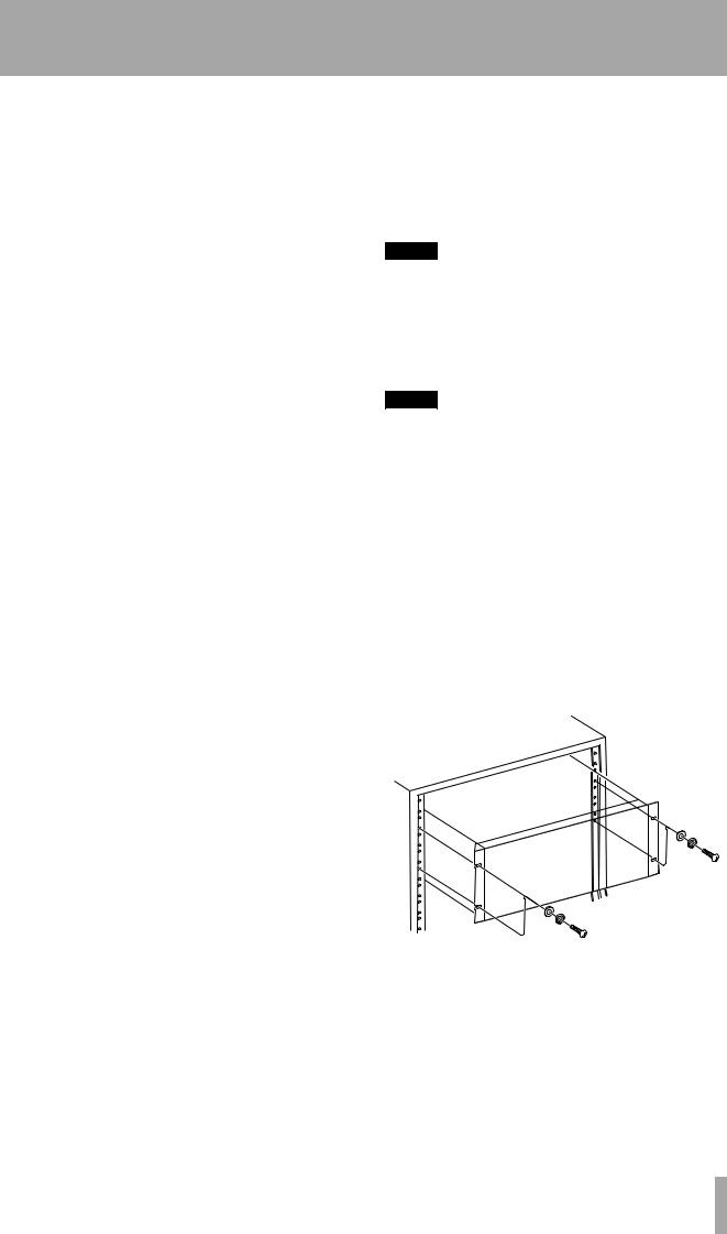
The DA-98HR may be installed in a standard 19” rack, occupying 4U of space. Since the DA-98HR is quite heavy (around 11kg – 24lb), your rack should be strong and stable to take the weight of the DA98HR.
The DA-98HR should be mounted with the front panel vertical.
1.4.5Electrical considerations
Make sure that your local power supply matches the voltage requirements marked on the rear panel of the DA-98HR.
If you are in any doubt concerning the local power supply, consult an electrician.
TASCAM DA-98HR 9

1 – Introduction to the DA-98HR–Recommended tapes
Avoid extreme voltage fluctuations. If necessary, use an input voltage regulator to smooth the power supplied to the DA-98HR.
Do not open the unit to clean inside, or to perform any internal adjustments. You should not attempt any cleaning or other maintenance procedures which are not described in this manual.
You may need to clean the heads occasionally. The procedure for doing this, and for checking tape error rates, etc., is given in 12, “Maintenance and settings”.
1.4.6Condensation
If you use the DA-98HR in a warm place after moving it from a cold place (for instance, recording on location), or if there has been a sudden change in temperature, condensation may occur within the tape mechanism, with a risk of possible damage to the unit.
If condensation does occur, you will not be able to operate the DA-98HR controls, and you will see the following message on the display:
W A R N I N G |
! |
C o n d e n s a t i o n |
o n d r u m |
|
|
If you see the above message, press the ESCAPE key to remove the message, leave the DA-98HR switched on for one or two hours, then switch it off and on again before starting recording.
If you are going to use the DA-98HR in a location where you think condensation is likely to occur, move the DA-98HR into the warmer location about one or two hours before recording is due to start, and leave it switched on. Turn the DA-98HR off and then on again before starting recording.
1.5Recommended tapes
The DA-98HR is designed for use with Hi8 video cassettes. You cannot use any other kind of tape with the DA-98HR.
There are two basic types of Hi8 tape: MP and ME. Each has its own particular characteristics and merits:
•MP tapes are manufactured using a daubed magnetic particle deposit process and exhibit a level of performance which is more than acceptable. They have a durability which allows them to be used as work tapes in studio and post-production environments.
•ME tapes have their magnetic layer produced through a metal evaporation process. Generally speaking, though these tapes have a high performance level, they are not as robust as MP tapes (see above) and should be used for live recording and archival purposes, rather than as work tapes.
TASCAM does not endorse any specific tape or tape manufacturer. TASCAM has licensed the use of the DTRS logo (  ) to tape manufacturers, provided their tape meets the specifications required by DTRS tape recorders. However, the use of the DTRS logo on the tape packaging does not imply any endorsement of the tape by TASCAM. It is possible that the characteristics and sensitivities of tapes may be changed by the manufacturers without notice. The brands and model numbers of tapes listed below may not always meet the specifications required by DTRS systems for optimum performance. TASCAM assumes no responsibility for problems resulting from changes made by a manufacturer to the materials or specifications of its tape products.
The electrical characteristics of DTRS recorders are adjusted and set using Sony Hi8 tape parameters (MP and ME) prior to shipment.
10 TASCAM DA-98HR
1 – Introduction to the DA-98HR–Recommended tapes
1.5.1Tape brands
The following brands and models of tape can be used with the DA-98HR. As mentioned above, this list does not constitute any endorsement by TASCAM of these products, nor is it a guarantee that tapes bearing this brand and model name will continue to give optimum performance.
Maker |
MP |
ME |
|
|
|
|
|
|
Fuji |
DPD-MP |
|
|
|
|
Quantegy |
DA8 MP |
|
|
|
|
BASF |
DA MP |
|
|
|
|
HHB |
DA113 |
|
|
|
|
Maxell |
DRS-113DA (P) |
|
|
|
|
Sony |
P6-HMP |
E5-HME |
|
|
|
|
P6-HMPX |
E6-HMEAD |
|
|
|
|
P5-HMP |
E5-HMEAD |
|
|
|
|
P5-HMPX |
E6-HMEX |
|
|
|
|
|
E5-HMEX |
|
|
|
|
DARS-MP |
E6-HME |
|
|
|
1.5.2Available recording and playback time
Depending on whether the tape has been purchased for use with an NTSC (P6/E6) or a PAL/SECAM (P5/E5) television system, the same length of tape (as far as video length is concerned) will provide different times for audio work, as shown below, due to different frame rates between television systems. The indication P6/E6 or P5/E5 will be printed on the tape package:
Time on tape |
P6/E6 (NTSC |
P5/E5 (PAL/ |
label |
tape) |
SECAM tape) |
|
|
|
|
|
|
20 |
18 |
25 |
|
|
|
30 |
27 |
37 |
|
|
|
45 |
40 |
56 |
|
|
|
60 |
54 |
75 |
|
|
|
90 |
81 |
113 |
|
|
|
120 |
108 |
– |
|
|
|
The electronics of DTRS recorders are designed to operate within specific parameters. The use of a tape with sensitivity higher or lower than that of tapes for which the DTRS recorder was originally designed may cause an error in functionality or prevent the user from getting optimum performance from the tape. Always use the shortest possible tape for a given project. Do not attempt to use 150-minute or longer tapes in DTRS machines, as the machine will detect the thickness of tape and automatically eject any tape thinner than recommended.
Never attempt to use a tape with the DA-98HR that has previously been used in video equipment.
NOTE
You cannot cut and splice DTRS 8mm tapes for editing purposes. Using a spliced tape in the DA-98HR will invariably result in serious damage to the heads, requiring replacement. All editing must be done digitally.
TASCAM DA-98HR 11
2 – Front and rear panels
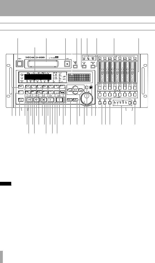
2.1Front Panel controls
1 |
2 |
3 |
46 5 |
7 |
8 |
9 |
A |
|
|
B |
|
|
|
CDE F G H I J |
P Q |
Y Z ae |
|
|
||
K L M N O R S b c d |
fgh i |
j |
k |
|||
T U |
V W X |
|
|
|
|
|
1 Power switch
Turns the power to the DA-98HR on and off. When the DA-98HR is turned off, settings will be retained in memory (12.3, “Memory backup”).
cator allow selection and viewing of the status of this monitoring mode.
For a full explanation of confidence monitoring, see 5.3, “Confidence mode”.
2 Tape loading slot |
5 Fs indicators |
Only use Hi8 ME or MP tapes as specified in 1.5, “Recommended tapes”. The DA-98HR will automatically eject all other tapes.
NOTE
Do not use a tape which has been used for recording video. Always use either new tapes or tapes which have been used in a DTRS recorder.
3 EJECT key
Ejects any loaded cassette. A cassette can only be ejected when the transport is stopped.
4CONFIDENCE MODE key and indicator
The DA-98HR features a confidence replay mode which allows off-tape monitoring. This key and indi-
These indicators (192kHz/176.4kHz, 96kHz/88.2kHz and 48kHz/44.1kHz) light to show what sampling frequencies are currently being used for recording.
6 HR MODE key and indicator
This key controls whether a tape will be formatted to record at 24-bit high resolution or 16-bit resolution. The indicator shows the status of the recording resolution while formatting, or if a previously-formatted tape has been loaded.
7 FORMAT/Fs key and indicator
The FORMAT indicator shows the tape formatting status. The FORMAT/Fs key controls the formatting of tapes and allows selection of the sampling frequencies to be used for recording (see 6.2, “Formatting a tape” for full details).
12 TASCAM DA-98HR

2 – Front and rear panels–Front Panel controls
8 AVAILABLE TRACK indicators
These tri-color indicators light when a track is available for recording, and the color shows the frequency at which the track will be recorded (as also shown by the FORMAT/Fs indicators 7).
9 Peak meters
These 15-segment peak meters show the input level or the recorded signal level, depending on the monitoring mode currently in operation (5, “Monitoring modes”). The ballistics and peak hold times are selectable (7.8.2, “Meter ballistics”).
The TIME CODE indicators show the timecode format currently in use. This can be any of the following: 30 (drop-frame DF or non-drop ND), 29.97 (drop-frame DF or non-drop ND), 25 or 24 fps.
The Fs(kHz) indicators show the current clock frequency (from the selected word sync source). The values are shown by the appropriate indicators here, and can be 192, 176.4, 96, 88.2, 48 or 44.1 (all kHz).
If pull-up or pull-down has been selected for telecine work, etc., the appropriate indicator (PULL UP, PULL DOWN) will light.
NOTE
When using digital recording equipment, there is no headroom above the 0dB mark and no tape saturation is possible. Any signal which causes the “OVER” segment to light will cause audible distortion. For this reason you should take care not to let recording levels exceed this level.
A Tape counter and status indicators
The tape counter gives the time in hours, minutes, seconds and frames.
The status indicators show the current status of various DA-98HR functions. The legends of these indicators are abbreviated for reasons of space. Here is a list of their full meanings, together with the pages on which the functions are more fully described:
Legend |
Meaning |
SIGNAL CONDITION |
Show the conditions of the appro- |
(WORD, VIDEO, MIDI/ |
priate inputs |
9PIN & EXT TC) |
|
PB CONDITION |
Playback condition (tape errors) |
REC INHI |
Recording is inhibited (the cas- |
|
sette’s write-protect tab is set) |
TAPE TC |
Shows the condition of the tape |
|
timecode track |
TIME MODE (ABS & |
Shows the timing reference cur- |
TC) |
rently being used |
TC GEN |
Lights when the internal timecode |
|
generator is generating |
OFFSET |
Machine offset is in operation |
OUTPUT PATCH |
Shows that the output patchbay is |
|
in operation |
DITHER |
Shows that dither mode is on |
SHTL MON |
Shows that the shuttle monitor |
|
mode is active |
DELAY |
Shows that at least one of the |
|
tracks has a non-zero delay time |
|
set |
VARI SPEED |
Lights when the DA-98HR’s vari |
|
speed function is enabled |
B Display screen
This 20-character by 4-line LCD screen shows the menus and the parameters that can be set in the menus.
C INPUT PATCH key and indicator
This key provides quick and easy access to the input patchbay screen 6.3.3, “Selecting input sources”.
The indicator shows that the patchbay is in use, even when the screen is not displayed. It goes out when all inputs are “normalled”.
D AES/EBU key and indicator
When recording from the built-in digital sources, one of either the TDIF-1 or the AES/EBU connectors may be in use at any time. When replaying, the signals are sent from both the TDIF-1 and the AES/ EBU connectors together.
Use this key to change the input source. When this key is off (the indicator is unlit), the TDIF-1 I/O is active, and when the key is on, the AES/EBU I/O is active. See also 6.3.2, “Selecting the digital source”.
E CHASE key and indicator
The CHASE key controls whether the DA-98HR’s transport is to “chase” a master machine (indicator is lit when chasing or flashing when preparing to chase) or to operate independently. The chase mode may be either timecode or ABS based (8, “DTRS synchronization” and 9.6, “Chasing to timecode”).
FLOCAL DISABLE (F1) key and indicator
When this key is on (the indicator is lit), the local controls have no effect (except for the STOP key), and the unit can be controlled only from a suitable remote control source.
When the 10KEY indicator Q is on, this key can be used to enter values directly, and when the SHIFT key S is pressed, this key becomes a function key.
TASCAM DA-98HR 13

2 – Front and rear panels–Front Panel controls
G CLEAR (F2) key
This key defeats the rehearsal and auto modes during auto punch-in and out (6.6, “Punch-in and punchout”).
When the 10KEY indicator Q is on, this key can be used to enter values directly, and when the SHIFT key S is pressed, this key becomes a function key.
H PREROLL (F3) and indicator
This key locates the tape to the punch-in point, minus the pre-roll time (see 6.6, “Punch-in and punch-out”). The indicator flashes while this location is taking place.
When the 10KEY indicator Q is on, this key can be used to enter values directly, and when the SHIFT key S is pressed, this key becomes a function key.
I AUTO PLAY (F4) key and indicator
When this key is pressed (the indicator lights), the DA-98HR will automatically start playing as soon as a preset location point has been reached (7.1, “Autolocation”).
When the 10KEY indicator Q is on, this key can be used to enter values directly, and when the SHIFT key S is pressed, this key becomes a function key.
J MEMO 1 (F5) key
When pressed, this key stores the current tape position into a memory location point which can be accessed using the LOC 1 key O. The location can be “nudged” using the menu functions (7.1.2, “Checking, editing and manually entering MEMO 1 and MEMO 2”).
When the 10KEY indicator Q is on, this key can be used to enter values directly, and when the SHIFT key S is pressed, this key becomes a function key.
K MIXDOWN (F6) key and indicator
When this key is pressed, the mixdown patchbay is in use, outputting a mixed stereo signal from channels 7 and 8. At this time, output from other channels is muted. See 5.4, “Mixdown patchbay” for details.
When the 10KEY indicator Q is on, this key can be used to enter values directly, and when the SHIFT key S is pressed, this key becomes a function key.
L RHSL (F7) key and indicator
This key and indicator allow selection of the rehearsal mode in auto punch-in and out (6.6, “Punch-in and punch-out”).
When the 10KEY indicator Q is on, this key can be used to enter values directly, and when the SHIFT key S is pressed, this key becomes a function key.
M AUTO PUNCH (F8) key and indicator
This key and indicator allow automatic punch-in and punch out following rehearsal (6.6, “Punch-in and punch-out”).
When the 10KEY indicator Q is on, this key can be used to enter values directly, and when the SHIFT key S is pressed, this key becomes a function key.
N REPEAT (F9) key and indicator
When this key is pressed, playback is repeated between the two memory locations set by J and P (7.2.6, “To start repeat play”).
When the 10KEY indicator Q is on, this key can be used to enter values directly, and when the SHIFT key S is pressed, this key becomes a function key.
O LOC 1 (F10) key
This key locates the tape to the position set by MEMO 1 J.
When the 10KEY indicator Q is on, this key can be used to enter values directly, and when the SHIFT key S is pressed, this key becomes a function key.
P MEMO 2 (+/–) key
When pressed, this key stores the current tape position into a memory location point which can be accessed using the LOC 2 key R.
When the function keys are used as number keys (the 10 , this key is used as a “sign-change” key.
Q 10KEY key and indicator
When this key is on (the indicator is lit), the keys from F through P become number keys for direct entry of values.
The digit entered by the keys is the same as that of their function number (Fx), except for the LOC 1/F10 key O, which enters a zero, and the MEMO 2 / +/– key P, which is used to change the sign of the entered value.
R LOC 2 (PRESET) key
This key locates the tape to the position set by
MEMO 2 P.
When the SHIFT key S is pressed, this key allows the assignment of the function keys F through O, (see 4.2.2, “The SHIFT key and function keys”).
14 TASCAM DA-98HR

2 – Front and rear panels–Front Panel controls
S SHIFT key and indicator
When this latching key is pressed (the indicator will flash), keys F through O become function keys, and the left and right cursor keys are used to save and load settings, respectively.
T REW key
Rewinds the tape at high speed.
The left and right keys (Ó and Á) are used for cursor navigation.
See 4, “Menu operations” for details of how to use these keys in menu operations.
When the SHIFT key S is active, the left and right keys (Óand Á) are used for saving and loading settings from tape (see 12.5, “Tape storage of settings”).
If this key is pressed during recording, recording will stop and the tape will rewind.
U F FWD key
Winds the tape forward at high speed.
If this key is pressed during recording, recording will stop and the tape will wind forward.
Z ENTER key
This key is used to confirm settings and to move ‘down” through the menu system.
a ESCAPE key
This key is used as an “exit” key and to move ‘upward” through the menu system.
NOTE
When either REW or F FWD is pressed for the first time after powering up, or loading a tape, the unit first configures itself for the reel hub diameter of the tape in use, during which the tape advances at low speeds. This takes several seconds. Thereafter, the transport momentarily goes into stop mode before the tape starts fast-winding. At the start and end of tapes, the transport momentarily goes into stop mode , and then advances at low speed, to prevent possible damage to tapes.
b DATA ENTRY key and indicator
When this key is on (the indicator is lit), the data entry/jog dial d can be used to make settings of numerical values, etc. in the menu system.
c JOG/SHUTTLE key and indicator
When this key is on (the indicator is lit). the data entry/jog dial d can be used to cue the tape playback position, in a similar way to “rock and roll” tape cueing on an open-reel tape deck.
V STOP key |
d Data Entry/Jog and Shuttle controls |
Cancels any current tape transport mode, and stops the tape.
W PLAY key
Starts playing the tape. If this key pressed while recording is in progress, the DA-98HR drops out of record mode.
X RECORD key
If the PLAY key W is pressed while the RECORD key is held down, recording will start on all armed tracks.
If the DA-98HR is in play mode, and the REC key is pressed, recording will start immediately on any armed tracks.
The RECORD key also is used to set punch-in points during auto punch-in/out operations (6.6.3, “Setting punch points “on the fly””).
Y CURSOR keys
These keys are used to navigate the cursor through the menus controlling the DA-98HR functions.
When a menu has been selected, the up and down keys (§ and ¶) are used to set the values or select the choices within the menu.
These controls consist of two parts, the inner jog dial, and the outer shuttle wheel.
When the DATA ENTRY key b is on (indicator lit), turning the jog dial clockwise increments the current menu parameter value, and turning it counter-clock- wise decrements the value.
When the JOG/SHUTTLE key c is on (indicator lit), turning the shuttle wheel to the right provides forward cueing and turning it to the left provides reverse cueing, similar to “rock and roll” on open-reel tape decks. The further the wheel is moved from the center position, the faster the tape speed. In this jog/shuttle mode, the inner jog dial is used to advance or retard the playback position by fractional amounts.
e REC FUNCTION keys and indicators
These eight keys and indicators allow the setting and viewing of the record status on a track-by-track basis.
When one of these keys is pressed, the appropriate indicator will flash, the track is “armed”, and going into record mode will start recording on that track. When recording is being carried out on a track, the track’s indicator will light steadily.
TASCAM DA-98HR 15

2 – Front and rear panels–Front Panel controls
f INPUT MONITOR keys and indicators
These keys allow the monitoring of inputs to tracks on a track-by-track basis, irrespective of the current transport status. The appropriate indicator(s) will light when monitoring track input(s) using these keys. Note that the function of these keys is connected with the ALL INPUT key h.
g ALL SAFE key and indicator
This key acts as a ‘safety lock”. When it is on (the indicator is lit), it prevents the arming (and hence the accidental recording) of any tracks.
h ALL INPUT key and indicator
When this key is pressed, the indicator will light, and, regardless of the transport mode, all outputs will be switched to the signals derived from the inputs. This is primarily for alignment purposes, and is equivalent to pressing all the INPUT MONITOR keys f together.
For a full treatment of monitoring modes on the DA98HR, see 5, “Monitoring modes”.
i AUTO MON key and indicator
When this key is pressed (the indicator will light), the monitoring system of the DA-98HR automatically changes between tape and input monitoring, depending on the transport mode.
For a full treatment of monitoring modes on the DA98HR, see 5, “Monitoring modes”.
j CLOCK key and indicators
This key and these indicators allow you to set and view the system clock. There are five options:
Setting |
Meaning |
INT |
The DA-98HR provides its own clock reference |
WORD |
The clock is synchronized to the signal received at |
|
the WORD SYNC IN connector |
VIDEO |
The clock is synchronized to the signal received at |
|
the VIDEO IN connector |
AES/EBU The clock is synchronized to digital audio received at the AES/EBU connector. The menu system is used to determine the channel from which the DA-98HR takes the clock.
SLOT The clock is synchronized to the input received at the optional slot input board, or derived from the slot’s clock
k TC REC key and indicator
This key is used to record timecode (either internally generated or from an external source) on a dedicated subcode track of the DA-98HR. No audio track is needed to record timecode. For full details of timecode operation, see 9, “Operations related to timecode”
NOTE
It is not necessary to use timecode if two DTRS units (e.g. DA-88, DA-38 or DA-98 machines) are to be operated together. The SYNC connections will ensure synchronization between machines (8, “DTRS synchronization”).
16 TASCAM DA-98HR
2 – Front and rear panels–Rear Panel connectors
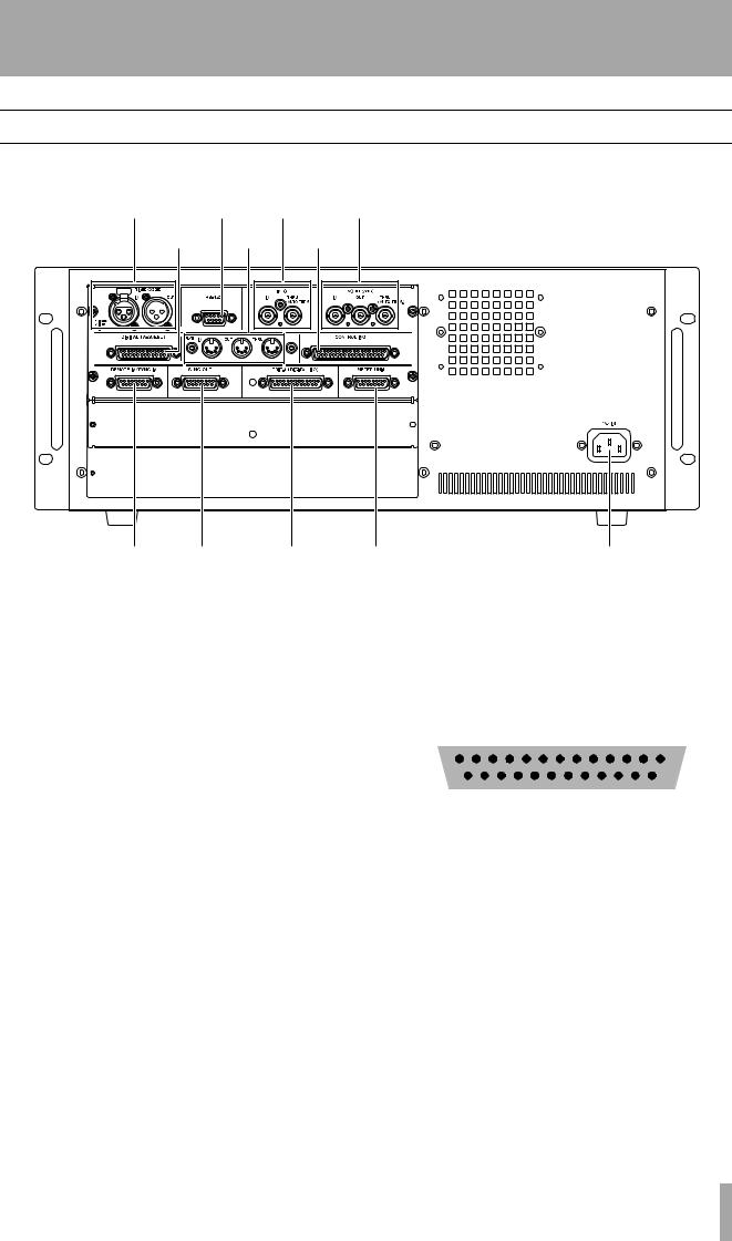
2.2Rear Panel connectors
This provides a brief description of the functions of the connectors on the rear panel. For full details of connections, see 3, “Connections”, and for details of levels, etc., see 13.2, “Specifications”.
l |
m |
n |
o |
p |
|
q |
r |
|
|
|
|
s t u l TIME CODE (IN and OUT)
This pair of XLR-type connectors (female for IN and male for OUT) provides the timecode connections for the timecode synchronization functions of the DA98HR. See 9, “Operations related to timecode” for full details.
m RS-422
This connector is used for controlling the DA-98HR using controllers or editors which conform to the Sony P2 protocol (RS-422). See 10.3, “Use with 9- pin external control” for full details of how to use other equipment connected through this connector.
n VIDEO (IN/THRU)
The VIDEO BNC connectors are used to carry video frame sync signals when the DA-98HR is used with video equipment. The self-terminating THRU connector echoes messages received at the IN.
See 9.7, “Video resolution” for details of video sync operation.
oWORD SYNC (IN/OUT/THRU (AUTO TERM))
v |
w |
p DIGITAL (AES/EBU)
This 25-pin D-sub connector provides I/O in AESEBU format. The pinouts for this are as follows:
|
1 Din |
2 Din |
3 Din |
4 Din |
1 Dout |
2 Dout |
3 Dout |
4 Dout |
|||||||
|
|
|
|
|
|
|
|
|
|
|
|
|
|
|
|
|
|
|
|
|
|
|
|
|
|
|
|
|
|
|
|
– + – + – + – + – + – + – + – + |
|||||||||||||||
|
|
|
|
|
|
|
|
|
|
|
|
|
|
|
|
|
|
|
|
|
|
|
|
|
|
|
|
|
|
|
|
|
|
|
|
|
|
|
|
|
|
|
|
|
|
|
|
|
|
|
|
|
|
|
|
|
|
|
|
|
|
|
|
|
|
|
|
|
|
|
|
|
|
|
|
|
|
|
|
|
|
|
|
|
|
|
|
|
|
|
|
|
|
|
|
|
|
|
|
|
|
|
|
|
|
|
|
|
|
|
|
|
|
|
|
|
|
|
|
|
|
|
|
|
|
|
|
|
|
|
|
|
|
|
|
|
|
|
|
|
|
|
|
|
|
|
|
|
|
|
|
|
|
|
|
|
|
|
|
|
|
|
|
|
|
|
|
|
|
|
|
|
|
|
13 |
|
|
|
|
|
|
|
|
|
|
|
|
|
|
|
|
|
|
|
|
|
|
|
|
|
|
|
|
|
|
|
|
|
|
|
|
1 |
||
|
|
|
|
|
|
|
|
|
|
|
|
|
|
|
||||||||||||||||||||||||||||
|
|
|
25 |
|
|
|
|
|
|
|
|
|
|
|
|
|
|
|
|
|
|
|
|
|
|
|
|
|
|
|
|
|
|
|
|
|
|
|
14 |
|||
|
|
|
|
|
|
|
|
|
|
|
|
|
|
|
|
|
|
|
|
|
|
|
|
|
|
|
|
|
|
|
|
|
|
|
|
|
||||||
Use a cable which provides suitable XLR-type connectors connected to a 25-pin ‘D’-sub connector, to connect the DA-98HRto the AES/EBU devices.
q MIDI IN/OUT/THRU
These connectors carry MIDI Time Code (MTC) and MMC (MIDI Machine Control) commands. See 10.5, “MIDI Machine Control” for details of how these facilities are used when synchronizing to other units.
r CONTROL I/O
These BNC connectors are used to carry the word clock between the DA-98HR and other types of digital audio equipment. The THRU connector is self-ter- minating. See 3.2.3, “Word sync clock connections” for full details.
This connector is used for control of the DA-98HR by external equipment. Consult your TASCAM dealer for full details of compatibility and the use of this connector.
TASCAM DA-98HR 17

2 – Front and rear panels–Rear Panel connectors
The pinout for this connector is given below .
Pin No. |
Signal |
Pin No. |
Signal |
|
|
|
|
|
|
|
|
1 |
PLAY |
20 |
SUB GND |
|
|
|
|
2 |
F FWD |
21 |
SERIAL OUT |
|
|
|
|
3 |
REW |
22 |
– |
|
|
|
|
4 |
AUX 1 |
23 |
SERIAL IN |
|
|
|
|
5 |
STOP |
24 |
– |
|
|
|
|
6 |
REC |
25 |
– |
|
|
|
|
7 |
AUX 2 |
26 |
– |
|
|
|
|
8 |
CHASE |
27 |
– |
|
|
|
|
9 |
– |
28 |
– |
|
|
|
|
10 |
SUB GND |
29 |
– |
|
|
|
|
11 |
PLAY TALLLY |
30 |
– |
|
|
|
|
12 |
F FWD TALLY |
31 |
– |
|
|
|
|
13 |
REW TALLY |
32 |
SRCK |
|
|
|
|
14 |
STOP TALLY |
33 |
– |
|
|
|
|
15 |
REC TALLY |
34 |
LOAD |
|
|
|
|
16 |
LOCK TALLY |
35 |
– |
|
|
|
|
17 |
AUX 1 TALLY |
36 |
SUB GND |
|
|
|
|
18 |
AUX 2 TALLY |
37 |
SUB 5 V (max |
|
|
|
50mA) |
|
|
|
|
19 |
ACTIVE SENSE |
|
|
|
|
|
|
s REMOTE IN/SYNC IN
This connector is used to connect another “master” DTRS unit (e.g. DA-98HR, DA-78HR, DA-98, DA-
88 or DA-38). See 8, “DTRS synchronization” for further details.
An RC-898, RC-848 or RC-828 remote control unit may also be connected here, but unless an “HR updated” RC-898 unit is used, not all functions of the DA-98HR will be available from the remote control unit.
t SYNC OUT
This is used to connect another DTRS unit in the “daisy-chain” or, if this DA-98HR is the last unit in the chain, to attach a termination plug.
u TDIF-1 (DIGITAL I/O)
This connector carries eight channels of digital audio to and from the DA-98HR in TEAC Digital Interface Format (TDIF-1).
v METER UNIT
This connector carries power and signals to drive 8 channels of the optional MU-8824 24-channel Meter Unit.
Make the connection using a TASCAM PW-88M cable.
w ~ IN
Use the provided AC power cord to connect the DA98HR to the AC power supply through this connector. Ensure that the power supplied is suitable for the unit (as marked ). If you are in any doubt at all regarding your power supply, consult a qualified electrician.
18 TASCAM DA-98HR

This section explains how to connect other equipment to the DA-98HR in a variety of situations. It is not intended as a complete reference to the use of the DA-98HR. See the appropriate sections for full details of how these connectors are used.
NOTE
When making connections between the DA-98HR and other equipment, whether audio or control, both the DA98HR and the other equipment must be turned off, otherwise damage may be caused to the DA-98HR and/or the other equipment.
Only use TASCAM-supplied and TASCAM-approved cables when making connections to the DA-98HR. Though the cables and connectors may resemble computer cables, they serve different purposes, and meet a different set of specifications. The use of cables other than TASCAM cables will at best cause the equipment to work erratically, and at worst cause damage to the equipment.
If the use of cables other than TASCAM cables causes or results in damage, the warranty is voided.
3.1Audio connection
Other audio equipment can be connected to the DA98HR either using optional analog or digital interfaces.
3.1.1Analog audio connections (optional IF-AN98HR)
All analog audio connections to the DA-98HR are made through 25-pin D-sub connectors to the optional analog slot 2-board set, IF-AN98HR.
This allows convenient and tidy cabling between the DA-98HR and other units such as the TASCAM M- 1600 series of mixing consoles.
It is not recommended that you make up your own cables—consult your TASCAM dealer for availability of suitable ready-made cables. However, we recognize that every situation has its own unique features, and there are occasions when a special cable must be made.
3 – Connections
Before starting to make the cable, we suggest you contact your TASCAM dealer for full details of cable specifications, etc.
The pinouts for both the ANALOG OUTPUT and INPUT connectors are given in the manual for these boards, as are detailed specifications and
All audio inputs are balanced and are rated at a nominal +4dBu level.
The impedance of the inputs is 20kΩ and that of the outputs is 10Ω.
3.1.2Digital audio connections (using TDIF-1)
TDIF-1 digital audio input and output signals are carried on the same 25-pin D-sub connector u.
To carry signals between a DA-98HR and another DTRS unit or a suitably-equipped digital mixing console, use a PW-88D cable (1 meter long) or a PW88DL cable (5 meters long).
NOTE
Although the TDIF-1 and AES connectors use the same type of 25-pin D-sub connector, it is not possible to connect a TDIF-1 -equipped unit directly to an AES/EBU-equipped unit. An interface such as the IF-AE8HR must be used to convert the signals.
3.1.3Digital audio connections (using AES/EBU)
The AES/EBU connections (strictly speaking, this format is AES3-1992 Amendment 3-1999) allow direct connections between the DA-98HR and suit- ably-equipped devices.
NOTE
If four dual-frequency (i.e. 88.2 kHz or 96 kHz) tracks have been selected as the available tracks, see also 7.10.3, “Setting the high-frequency AES/EBU I/O transfer mode”.
The AES x2 IO menu item (menu group A), allows the choice of either dual line or high speed data connections. Note that this menu option is only available when the dual-speed x 4 option is selected for the available tracks (see also 6.2.1, “Available tracks”).
TASCAM DA-98HR 19

3 – Connections–Synchronization connections
In all other cases, the data is transferred according to the following table, where the numbers represent the track which is being transferred. Italicized numerals (e.g. 2) indicate that the signal is being transferred at double speed:
|
tracks)(24x |
|
2x |
tracks)(32x + tracks)(2base |
tracks)(22x + tracks)(4base |
tracks)(8base |
||
Output |
(4 tracks) |
|||||||
|
|
|
|
|||||
|
|
|
|
|
|
|
||
channel |
|
HSa |
|
DLb |
|
|
|
|
|
|
|
|
|
|
|||
|
|
|
|
|
|
|
|
|
|
|
|
|
|
|
|
|
|
1 |
1 |
1 |
|
1 |
1 |
1 |
1 |
|
|
|
|
|
|
|
|
|
|
2 |
1 |
2 |
|
1 |
1 |
1 |
2 |
|
|
|
|
|
|
|
|
|
|
3 |
— |
— |
|
2 |
2 |
2 |
3 |
|
|
|
|
|
|
|
|
|
|
4 |
— |
— |
|
2 |
2 |
2 |
4 |
|
|
|
|
|
|
|
|
|
|
5 |
2 |
3 |
|
3 |
3 |
3 |
5 |
|
|
|
|
|
|
|
|
|
|
6 |
2 |
4 |
|
3 |
3 |
4 |
6 |
|
|
|
|
|
|
|
|
|
|
7 |
— |
— |
|
4 |
4 |
5 |
7 |
|
|
|
|
|
|
|
|
|
|
8 |
— |
— |
|
4 |
5 |
6 |
8 |
|
|
|
|
|
|
|
|
|
|
a.High speed b.Dual line
3.2Synchronization connections
The DA-98HR is equipped with sophisticated facilities for control and synchronization with other units. For full details of how to operate the DA-98HR with other DTRS units, see 8, “DTRS synchronization”, and for details of timecode synchronization, see 9, “Operations related to timecode”.
3.2.1Analog timecode connections
The DA-98HR can be synchronized to externallygenerated timecode and is also equipped with an internal timecode generator.
The two XLR timecode connectors l carry balanced signals with the following polarity:
Pin # Connection
1Ground
2Hot
3Cold
However, unbalanced signals may be used, with only pins 1 and 2 connected.
|
IN (balanced) |
OUT (balanced) |
|
|
|
Level |
0.5 Vp-p to 10.0Vp-p |
2Vp-p |
|
|
|
Impedance |
> 10kΩ |
< 100 Ω |
The TIMECODE OUT connector transmits internallygenerated timecode or re-shaped or re-generated timecode echoed from the TIMECODE IN connector.
3.2.2Video connections
These BNC connectors n are used to provide video frame reference clocking when the DA-98HR is used with video equipment.
The front panel CLOCK switch j is used to change between clock sources, and should be set to VIDEO when synchronizing to video sync.
Connect the VIDEO IN connector of the DA-98HR to the VIDEO OUT of a video sync generator unit. This signal should be a 1 Vp-p composite signal.
If other equipment (such as other DTRS units) also need the video frame reference clock, the signal received at the VIDEO IN is echoed at the VIDEO THRU connector.
If the DA-98HR is the last unit in the chain of video equipment, there is no need to terminate it, as this circuit is self-terminating.
For details of how the DA-98HR can be synchronized to video frame information, see 9.7, “Video resolution”.
3.2.3Word sync clock connections
This set of BNC connectors o is used to synchronize the DA-98HR to other digital audio devices.
The front panel CLOCK switch j is used to change between clock sources, and should be set to WORD when synchronizing to an external word sync clock.
The IN jack should be connected to the WORD SYNC OUT of the digital audio device from which the DA-98HR is to receive the synchronization clock.
Note the difference between the OUT and the THRU connectors. OUT is used to carry word clock signals generated by the DA-98HR, and THRU is used to echo the signals received at IN.
If the DA-98HR is the last unit in the word clock chain, there is no need to terminate it, as this circuit is self-terminating.
Also note that if the DA-98HR is connected to other DTRS units using a PW-88S cable as described in 8,
20 TASCAM DA-98HR
3 – Connections–Control connections
“DTRS synchronization”, the WORD SYNC jacks do not need to be connected between the DTRS units.
3.3Control connections
3.3.1RS-422 connector
This connector is used to connect the DA-98HR to other controllers or editors which will control the DA-98HR using the Sony P2 protocol, or a bus protocol. See 10, “External control” for details.
If you are in doubt about the compatibility of such a device, please consult TASCAM or your TASCAM dealer, who will be able to advise you.
The DA-98HR can emulate (through software control accessed through menu 6) a number of devices for compatibility with almost any controller.
3.4.1Multiple DTRS units
Use a TASCAM PW-88S cable when connecting other units to the REMOTE/SYNC IN connector s or to the SYNC OUT connector t.
This synchronization cable will carry the internal synchronization code and the transport signals, etc. There is no need to make any other connections, apart from the audio connections (either digital or analog).
If more than one DTRS unit is to be used, the first unit in the chain must have its Machine ID set to “1”, (“0” in the case of DA-88s) and subsequent units must have their IDs set in order with no gaps in the numbering sequence. Note that the diagram below does not show any audio connections.
Machine ID 1 |
Machine ID 2 |
Machine ID 3 |
||||||||||||
|
(master) |
|
(slave 1) |
|
(slave 2) |
|||||||||
|
|
|
|
|
|
|
|
|
|
|
|
|
|
|
|
|
|
|
|
|
|
|
|
|
|
|
|
|
|
3.3.2MIDI connectors (IN , OUT and THRU)
These standard 5-pin DIN MIDI connectors q are used to carry MIDI Time Code (MTC) and MIDI Machine Control (MMC) information between the DA-98HR and other suitably-equipped units (for instance, sequencers capable of being synchronized to MTC, and capable of transmitting MMC commands).
The MIDI functions are accessed through menu group 7. See 10.5, “MIDI Machine Control” for full details.
Note the difference between MIDI OUT and MIDI THRU. The OUT connector outputs signals which originate from the DA-98HR. The THRU connector echoes messages received at the IN.
3.3.3Parallel control
Parallel control by and of the DA-98HR is performed through the CONTROL I/O port r. See this section for details of how to connect other equipment to this port.
3.4Connection to other TASCAM units
By a “TASCAM unit”, we mean another DA-98HR, a DA-98, a DA-88 or a DA-38 unit, or an optional remote control unit, or digital mixing console incorporating remote control facilities, which may also be connected in a “chain” with multiple DTRS units.
|
|
|
|
|
|
|
|
|
|
|
|
|
|
|
|
|
|
|
|
|
|
|
|
|
|
|
|
|
|
|
|
|
|
|
|
|
|
|
|
|
|
|
|
|
|
|
|
|
|
|
|
|
|
|
|
|
|
|
|
|
|
|
|
|
|
|
|
|
|
|
|
|
|
|
|
|
|
|
|
|
|
|
|
|
|
|
|
|
|
|
|
|
|
|
|
|
|
|
|
|
|
|
|
|
|
|
|
|
|
|
|
|
|
|
|
|
|
|
|
|
|
|
|
|
|
|
|
|
|
|
|
|
|
|
|
|
|
|
|
|
|
|
|
|
|
|
|
|
|
|
|
|
|
|
|
|
|
|
|
|
|
|
PW-88S |
|
|
|
|
|
|
|
PW-88S |
|
Termination |
||||||||||||
|
|
|
|
|
|
|
|
|
|
|
|
|
|
|
|
|
|
|
|
|
|
|
|
|
|
|
plug |
|||
See 8.2.2, “Setting machine ID” for details of setting the Machine ID using menu group 3.
NOTE
The last unit in the chain must be terminated (a TASCAM termination plug must be plugged into the SYNC OUT of the last machine in the chain.
Once again, only use TASCAM cables for connection of equipment to and from the DA-98HR.
The total length of remote/sync cables in the chain should not exceed 15 m (approximately 50 ft.).
3.4.2“Indirect” word sync
As mentioned earlier, there is usually no need to use a word clock when connecting DTRS units together. There is, however, a special case when it is necessary to carry external word sync between DTRS units.
This is when a slave DTRS unit is recording digitally from another digital audio device:
|
|
Digital SDIF-2 |
|
|
|
device |
|
|
Word clock signal |
|
|
Machine ID 1 |
Machine ID 2 |
|
|
(master, but |
|
||
(slave 1) |
|
||
CLOCK set to |
SDIF-2 |
||
digital audio |
|||
WORD) |
|
||
|
|
IF-88SD |
PW-88S Termination TDIF-1 digital plug audio
TASCAM DA-98HR 21

3 – Connections–Connection to other TASCAM units
Though the slave will receive its word clock from the master unit, the master itself must receive its word clock from the other digital audio device.
In this case, the master unit will have its clock source set to WORD, and the slave will receive its clock from the master unit through the SYNC IN s.
3.4.3Meter unit (MU-8824)
The optional MU-8824 external meter bridge unit can be connected using a PW-88M cable from the METER UNIT connector v. You do not need to make any settings on the DA-98HR when connecting the meter unit.
22 TASCAM DA-98HR

Read this section to understand the basic principles of menu operation. This will help you find your way round the DA-98HR’s functions easily and quickly.
4.1The menus
The DA-98HR has fifteen menu groups, labeled from 0 through 9, and A, B, D, E and F. These are referred to in this manual as “menu group 0”, menu group E”, etc.
The menu which is used to select these menus is called the “top” menu, and looks like this
S e l e c t M e n u |
G r o u p |
||||||
˘ 0 |
1 |
2 |
3 |
4 |
5 |
6 |
7 |
8 |
9 |
A |
B . |
D |
E |
F |
|
D l y / I n P a c h / V a r i / L o c t |
|||||||
|
|
|
|
|
|
|
|
The bottom row of the display is used as a quick reference to remind you of the currently-set value or the contents of the menu group.
4.1.1Navigation around the menu system
The cursor keys Y are used to navigate round the screen. In this manual, we sometimes use the following terms for these keys:
CURSOR Term used in text key
§UP key
¶DOWN key
ÓLEFT key
ÁRIGHT key
Notice that in the top menu, as you move the cursor between menus, the bottom line changes, reflecting the contents of the menu.
4.1.2Using the ENTER key
From the top menu, when the cursor is beside the desired menu group, press ENTER Z to enter that menu group. The screen changes to show the choices within that group.
These are the choices within menu 0:
˘ D e l a y |
M e m o 1 |
|
I n |
P a t c h |
M e m o 2 |
V a r i S p d |
L o c P r e |
|
1 |
0 0 0 0 S a m p l e |
|
|
|
|
4 – Menu operations
Use the cursor keys to navigate between menu items within the group. The bottom line of the display changes to show the currently-set values for the parameter beside the cursor.
When the cursor is beside the desired parameter, press the ENTER key. You can now change the values of that parameter.
4.1.3The ESCAPE key
The ESCAPE key a is used to move up through the menu hierarchy (from menu screens to sub-menus to the top menu). It is therefore used if you enter the wrong menu by mistake.
For a full description of the menu tree, see the Quick Start guide or 11, “Menu and parameter reference”.
4.1.4Editing values
When a parameter has been selected for editing, the function of the cursor keys is changed.
If there is only one parameter, the Óand Ákeys are not used, and the §and ¶ keys are used to change the value of the parameter. If the parameter is a number, the § key increases the value and the ¶ key decreases the value.
The “cursor” in these menus usually refers to a blinking value on the display, which is the value that can be edited. When we say “move the cursor”, what we are referring to is making a value on the display blink.
If there is more than one parameter or there are “subvalues” to the parameter, such as in the following example for setting the internal timecode generator start time ( which is accessed from menu group 8), the procedure is a little different:
G e n e r a t e S t a r t T i m e
0 0 : 0 0 : 0 0 : 0 0 |
3 0 N D F |
|
|
Here, the internal timecode generator start time can be set. Obviously, we could edit the “frames” field and keep pressing the § key, but one hour would be 30 x 60 x 60 = 10,800 key presses!
To avoid this, the Áand Ókeys move the cursor (as shown by blinking characters) between the “fields”; in this case, hours, minutes, seconds and frames.
Regardless of whether one value or several sub-val- ues have been edited, the changes to the values are made immediately. The cursor keys can then be used for navigation again.
TASCAM DA-98HR 23
4 – Menu operations–About the function keys
In most time-based menus, when the “frames” field is being edited, the value can be changed from 00 to the number of frames in 1 second (the exact number varies between settings) and back to 00.
However, if the cursor is moved to an invisible “field” to the right of the displayed values, so that the whole of the time value blinks, incrementing the value of the frames field above the number of frames in a second will increment the seconds field.
As an example:
1The menu screen shows: 00:01:43:29 when the frame rate is 30fps.
The 29 indicates that these characters are blinking.
2Press §.
3The menu screen shows: 00:01:43:00.
However:
1The menu screen shows 00:01:43:29.
2Press §.
3The menu screen shows: 00:01:44:00.
The whole time value has been incremented, not just the frames field.
4.1.5Resetting a menu value
Sometimes it is necessary to reset a menu value to a default value.
To do this quickly, hold down the § key and press the ¶key (or hold down the ¶ key and press the § key).
If the menu value is an individual field in a time value, as described, all the fields are reset to zero. If the whole time value is flashing, this action also resets the whole of the time value. If there is more than one independent field in a menu screen, use the cursor to point to the value that you want to reset to zero and then perform this action.
4.1.6Changing menu values fast
Sometimes it is useful to be able to change a value fast (for instance, time values such as minutes and seconds). To do this, hold down the § or ¶key and press the ENTER key. The values will change faster as long as the ENTER key is held down.
4.1.7Using the dial to change values
It is also possible to use the dial to change values. This can be a convenient way of making larger changes to numeric values.
1Press the DATA ENTRY key b so that the indicator lights.
Note that if the JOG/SHUTTLE indicator c is lit (i.e. the dial is being used for jog control), it goes out when the DATA ENTRY key is pressed.
2With the cursor on a data entry field, turn the dial to change the value (clockwise to increment, counterclockwise to decrement).
3When you have finished using the dial as a data entry, you can turn off the DATA ENTRY indicator (press the key once again), or press the JOG/SHUTTLE key so that the dial can be used for jog and shuttle operations.
NOTE
In this manual, we often use the phrase “use the §and ¶ keys to set the value”. In almost all cases, when these keys can be used, the dial can also be used as described above, even when this is not explicitly mentioned.
4.1.8Blanking the screen display
There are times when you may want to blank the backlit screen display (for instance, the light may be a visual distraction, or you may want to discourage tampering fingers).
1Press the ENTER key, and while holding it down, press ESCAPE (you can also hold down the ESCAPE key and press ENTER).
The screen blanks, and the back light goes out.
2To restore the screen display, press any of the following: ENTER, ESCAPE, or any of the
CURSOR keys.
The screen relights, and shows the top menu.
NOTE
This can also be used as an alternative way of returning to the top menu when you are inside the menu hierarchy.
4.2About the function keys
These keys (F through O) may be used as quickjump keys to commonly-used menus, or can be used as quick location keys.
4.2.1Function key modes
These keys are often used to jump to frequently-used menus (4.3, “Assigning menus to function keys”), but their function can be changed, as described here:
1Go to menu group 7, move the cursor to
FunctMode and press ENTER.
24 TASCAM DA-98HR
4 – Menu operations–Assigning menus to function keys
2This menu gives you two choices, Menu, and
Locate Position:
F u n c t i o n K e y M o d e
S e l e c t
M e n u
Menu uses the function keys as a quick way of jumping around the menu system (4.3, “Assigning menus to function keys”).
Locate Position assigns the ten function keys to location memories (7.2, “Function key location memories”)
3 Select the option with the § and ¶ keys.
NOTE
When you change the function of the “soft” keys between menu and location functions, the values assigned to the other function are not lost, and are restored when you next change the function of the soft keys.
4.2.2The SHIFT key and function keys
many of the menu functions only rarely (for instance, whether the DA-98HRHR is a master or a slave unit).
The “F” keys below the tape counter (F through O) can be used as “soft keys”, providing quick access to the menu screens you use most often.
4.3.1To assign a menu screen to a key
1Set the function key mode to Menu as described in 4.2.1, “Function key modes”
2Use the cursor and ENTER keys to display the menu function you want to assign to a key.
3Press the SHIFT key S (the indicator will flash).
4Press the PRESET key R. The following will appear on the display. The bottom line shows the menu as selected in step 2.
F u n c t i o n P r e s e t
P U S H F U N C T I O N K E Y
T i m e c o d e O f f s e t
Usually, the 10 function keys and the LOC 2/PRESET and MEMO 2/ +/– keys perform the duties as marked on the top of their labels (e.g. key G usually works as the CLEAR key).
To use the keys as function keys (whether location keys, or as preset menu keys):
1Press the SHIFT key. The SHIFT indicator starts to flash.
While it is flashing, these keys are used as described on the bottom row of their labels (e.g. key H now becomes function key 3 (F3)).
2Pressing a function key in menu mode will turn off the flashing SHIFT indicator, but the SHIFT indicator continues to flash in location mode after a function key has been pressed.
3If the SHIFT indicator is flashing, press the SHIFT key again to stop the indicator flashing and return the keys to their original functions of their top printed labels.
4.3Assigning menus to function keys
It is quite likely that you will find yourself using a few of the same menu functions many times (for instance, manual adjustment of punch points) and
5Press the key (F1 through F10) to which you want to assign the menu screen.
This assigns the menu screen to the key and the SHIFT indicator goes out.
4.3.2Recalling an assigned menu function
1When the function key is set to Menu (4.2.1, “Function key modes”), press the SHIFT key S
(the indicator flashes).
2Press the F key (1 through 10) which has been assigned to the menu function you want to recall.
The menu screen is recalled, and the SHIFT indicator goes out.
4.4Using the function keys as number keys
Press the 10KEY key Q so that the indicator flashes.
While the indicator is flashing, the function keys are used to enter the digit (F1 enters a 1, F 2 enters a 2, etc.) except for F 10, which enters a 0. The MEMO 2 key P is used to change the sign of numeric entries where appropriate.
TASCAM DA-98HR 25
4 – Menu operations–Using the function keys as number keys
If a time value is being entered, and an individual field is blinking (hh, mm, ss, ff, etc.), pressing the 10KEY key and then entering a numeric value causes the whole time field to be reset and start blinking. Values are added from the right, so that:
Key
Display shows
pressed
F1 00:00:00:01
F3 00:00:00:13
F4 00:00:01:34
F7 00:00:17:34
etc.
When you have entered the value (e.g. a location memory) using the function keys as number keys), you should press the 10KEY key to stop the 10KEY indicator flashing. Pressing the ENTER key will correct any erroneous entries (e.g. a seconds value of 99 will be corrected to 59).
You can use the function keys as number keys in almost any menu where direct numerical input is possible.
You cannot use these keys as number keys when there are only two choices (even if they are numerical). An example of such a menu is the Rechase Mode menu (9.6.10, “Rechasing timecode”), where the two options for the Window value are 1 second and 2 seconds. This parameter should be set using the § and ¶ keys, not the number keys.
The following is a step-by-step guide to entering a value (1 minute and 5 seconds) into the Locate Preroll parameter (7.1.3, “Setting the location pre-roll time”).
1Press the 10KEY key so that the indicator flashes.
2Go to menu group 0, move the cursor to Loc Pre, and press ENTER:
L o c a t e P r e - r o l l
0 0 m i n 0 0 s e c
3 Press the F1 key F:
L o c a t e P r e - r o l l
0 0 m i n 0 1 s e c
The figures on the bottom line of the display start to blink, showing that you are entering numerical data.
Notice that the number is entered from the right of the fields.
4 Press the F10 key O (to enter a 0):
L o c a t e P r e - r o l l
0 0 m i n 1 0 s e c
5 Press the F 5 key J:
L o c a t e P r e - r o l l
0 1 m i n 0 5 s e c
6The numbers for this value have now been entered, but the value itself has not. Press the ENTER key Z to enter the value.
The bottom line of the display stops blinking and the 10KEY indicator stops flashing.
7You can also use the § and ¶keys (or the dial) to adjust the value you have just entered.
26 TASCAM DA-98HR

NOTE
We strongly advise you to read this section—the effective use of multitrack monitoring is one of the keys to an efficient recording session.
Like all multitrack recorders, the DA-98HR has a number of different monitoring modes, depending on the current monitor status, transport status and whether the track is armed or not.
In addition to the “standard” modes common to most multitrack recorders, the DA-98HR includes two special monitoring features: the CONFIDENCE MODE 4, and the individual track INPUT MONITOR switches . These are described in this section.
5.1Monitoring controls
The controls which affect monitoring are:
•ALL INPUT h
•INPUT MONITOR f
•REC FUNCTION e
•CONFIDENCE MODE 4
•AUTO MON i
5.1.1ALL INPUT and INPUT MONITOR
When these are active, the signal from the DA98HR’s outputs will always be the input source signal received at the input for the appropriate track or tracks.
When the ALL INPUT key is pressed, its indicator and the INPUT MONITOR indicators of all tracks light. Monitoring for all tracks is then of the input sources.
When the ALL INPUT key is pressed again to turn off this mode, the status of the INPUT MONITOR indicators will revert to the status before the ALL INPUT key was turned on.
The INPUT MONITOR switches are disabled until the ALL INPUT key is turned off (the ALL INPUT indicator goes out).
The INPUT MONITOR switches allow you to perform the same function on a track-by-track basis, allowing you to check the input source, and are available from a number of modes as described in the table below.
5.1.2AUTO MON
When replaying a track, you will usually want to monitor the program material recorded on the tape. However, there are times when you want to monitor
5 – Monitoring modes
the source input rather than the recorded signal, even in play mode.
The following table shows what will be monitored from a track. This depends on the AUTO MON and the REC FUNCTION switch settings, and on the transport mode currently engaged.
AUTO MON |
REC FUNCTION (track arming) |
PLAY |
RECORD |
STOP, etc. |
|
|
|
|
|
|
|
|
|
|
ON |
ON |
Tape |
Source |
Source |
|
|
|
|
|
ON |
OFF |
Selectablea |
Selectable |
Selectable |
OFF |
ON |
Selectable |
Sourceb |
Selectable |
OFF |
OFF |
Selectable |
Selectable |
Selectable |
|
|
|
|
|
a.“Selectable” as used here means that individual tracks’ INPUT MONITOR switches can be used to switch between source and tape monitoring. Tape monitoring is obviously only possible when the tape is moving (in recording or playback modes).
b.Confidence mode (5.3, “Confidence mode”) is possible in this mode (AUTO MON off and REC FUNCTION on) and when confidence mode is active, the monitoring is selectable between source and tape.
The AUTO MON function therefore allows you to switch automatically between monitoring modes as the tape transport function changes.
NOTE
The ALL INPUT key overrides the monitoring mode from the table above (when this mode is active, monitoring for all tracks will always be source monitoring, regardless of the status of AUTO MON).
5.1.3Shuttle monitoring
In addition to these modes, there is one further menu item, that affects monitoring, but only in one special case – shuttle mode. Usually, when shuttling the tape, you will want to monitor the tape. However, if a track is armed, you may want to listen to the source input signal, rather than the recorded signals.
NOTE
ALL INPUT overrides any shuttle monitoring selections described below. Any shuttle monitoring while ALL INPUT is on will always be source monitoring.
To turn shuttle monitoring on and off:
TASCAM DA-98HR 27
5 – Monitoring modes–Patching the outputs
1From menu group 2, move the cursor to Shtl Mon, and press ENTER:
S h u t t l e M o n i t o r
o f f
2Use the § and ¶ keys to change the setting between on and off.
The shuttle monitoring setting key has no effect when AUTO MON is off. While shuttling, you can use tracks’ INPUT MONITOR switches (regardless of arming status) to change between source and tape monitoring.
When the AUTO MON and shuttle monitoring are both on (the indicators will light), the output from all armed tracks will be the source input. This cannot be changed.
NOTE
You can always (regardless of any other status except ALL INPUT) use the INPUT MONITOR switch of unarmed tracks to switch between source and tape monitoring.
If AUTO MON is on, but the shuttle monitoring mode is turned off, all armed tracks will monitor the recorded signals in shuttle mode. This cannot be changed.
1From menu group B, move the cursor to Out Patch, and press ENTER:
O u t p u t |
P a t c h |
|
|
|
|
||
c h 1 |
2 |
3 |
4 |
5 |
6 |
7 |
8 |
T r k ˘ 1 |
3 |
2 |
4 |
5 |
6 |
8 |
8 |
|
|
|
|
|
|
|
|
2Use the Ó and Á keys to select the track (Trk) which will be routed to the output channel. Use the § and ¶keys to change the value at the cursor.
Note that a track may be routed to more than one channel. In the screen above, the routing is “normalled”, except that tracks 2 and 3 are routed to output channels 3 and 2 respectively, and track 8 is paralleled to channels 7 and 8.
When the outputs are not “normalled”, i.e. there is no longer a one-to-one correspondence between the tracks and the output channels, the OUTPUT PATCH indicator under the tape counter lights.
NOTE
The number of tracks available, and their possible assignments, vary according to the number of available tracks (6.2.1, “Available tracks”).
NOTE
You can also disable shuttle monitoring with the Shuttle Mute function (7.6.2, “Shuttle muting”).
Shuttle monitoring is attenuated by 12 dB compared with other monitoring modes. This helps to avoid damage to tweeters, etc. when shuttling fast.
5.2Patching the outputs
The tracks do not have to be assigned to the outputs on a one-to-one basis. This may be useful in situations where a digital audio patchbay is not available.
NOTE
Note that this routing function only allows rerouting between tracks of the same sampling frequency. It is not possible, for instance, to assign a double-frequency track to an output which would normally be used by a base-fre- quency track.
The outputs are made in parallel on both the AES/ EBU and the TDIF-1 outputs (though only one may be selected at a time). If an optional slot board has been installed, the outputs will also be output from there.
5.3Confidence mode
When recording in a studio, it is usual to monitor the input signals, rather than the tape. This allows accurate synchronization between studio events and the actions of the control room staff. If a “glitch” is later discovered in the recording, or it is discovered that a signal has been wrongly routed, resulting in an unwanted recording being produced, it is a relatively simple matter to re-record the take.
In a live recording situation, this luxury is not possible. One can hardly ask an orchestra giving a concert to repeat a movement of a symphony for re-recording purposes!
For this reason, the DA-98HR includes a confidence mode which permits off-tape monitoring on a track- by-track basis while recording is in progress.
Confidence mode provides monitoring off-tape while recording for all tracks, except those tracks whose INPUT MONITOR switch is active. The monitoring of these tracks will be the input source, not tape.
The actual mechanics of how this is accomplished internally are quite complex, but the result is that off-
28 TASCAM DA-98HR

5 – Monitoring modes–Mixdown patchbay
tape signals are delayed by about 240 milliseconds relative to the input signal. This means that it is not recommended that you perform punch-ins, etc. in the confidence mode.
In the confidence mode, overdubbing will be out of sync with previously recorded tracks, as well as with the input source.
We suggest you use confidence mode only when laying down long takes of basic tracks which will not need punching for correction (e.g. laying down tracks from a video worktape, or classical live recordings). You may also choose to use confidence mode when you are dubbing from another audio multitrack tape to the DA-98HR, to ensure the quality of the transfer.
Another use for the confidence mode is when you are recording using dither (7.12, “Dither”). You may want to check the effects of dither on the re-quan- tized recording as the tracks are being laid down.
5.3.1Arming tracks in pairs
Note that in confidence mode, tracks at the base sampling frequency are always armed and unarmed in pairs (1+2, 3+4, 5+6, 7+8). Dual-frequency and quad-frequency tracks may be armed and unarmed individually.
NOTE
Turning on confidence mode unarms any tracks which have been armed prior to turning on confidence mode.
1Pressing the REC FUNCTION of either track 3 or track 4, for instance, will arm both tracks 3 and 4(provided these are base-frequency tracks).
2Pressing either track 3 or track 4’s REC FUNCTION key will unarm both tracks (regardless of which track’s REC FUNCTION key was used to arm the tracks).
3If confidence mode is turned off, track arming and unarming can now be carried out on a track-by-track basis.
Even if tracks were armed in pairs while confidence mode was enabled, when confidence mode is disabled, they can now be unarmed individually.
5.3.2Using confidence mode
1Adjust the recording levels on all armed tracks.
2Turn off AUTO MON mode and make sure that the ALL INPUT switch is off.
NOTE
Using confidence mode, it is possible to monitor some tracks off-tape during recording while monitoring the input source of others. However, as explained above, the way in which the confidence mode is implemented means that the off-tape signals are delayed by 240 milliseconds relative to the input source signals. Hence, the off-tape and source signals will be out of sync. We therefore recommend that this function is only used when dubbing.
3Press the CONFIDENCE MODE key 4 once.
The indicator will flash.
4Press the CONFIDENCE MODE key again within five seconds of pressing it for the first time. The indicator will light steadily.
If you do not press the CONFIDENCE MODE key twice within five seconds, the indicator will stop flashing. This is to stop you from entering the confidence mode by accident.
5To leave confidence mode, press the CONFIDENCE MODE key once.
5.4Mixdown patchbay
In addition to the routing, it is also possible to mix down eight signals (as a mixture of off-tape and input signals) to outputs 7 and 8. These outputs are paralleled on the AES/EBU and TDIF-1 digital outputs (though only one of these can be selected at one time) as well as on any optional slot boards fitted to the DA-98HR.
In this way, a rough stereo mix, with channel level and pan, and a master level, can be produced without the need for a mixing console (for example, the AES/ EBU outputs can be used to feed a DAT recorder, whose headphone amplifier is then used as the monitoring source).
5.4.1Turning on the MIXDOWN mode
The mixdown mode is turned on and off using the MIXDOWN key K. When this indicator is lit, the mixdown is in operation, and signals will only be received at the 7 and 8 output channels.
NOTE
The mixdown function is only available when all eight tracks have been selected at the base frequency (44.1 kHz or 48 kHz).
Also note that when the mixdown mode is in operation (i.e. the MIXDOWN indicator is lit), the output channels which are not used for the mixdown (1 through 6) are not used.
TASCAM DA-98HR 29

5 – Monitoring modes–Mixdown patchbay
5.4.2Selecting the mixdown sources
1From menu group B, move the cursor to MixInSel, and press ENTER:
M i x I n p u t S e l e c t |
|
|
|||||
T r k 1 |
2 |
3 |
4 |
5 |
6 |
7 |
8 |
S r c ˘ T T T T D S S S |
|||||||
c h 1 |
3 |
2 |
4 |
5 |
6 |
7 |
8 |
|
|
|
|
|
|
|
|
Here, T signifies a tape track, S indicates a channel from an optional board fitted in the expansion slot (e.g. the IF-AN98HR) and D indicates a digital source (i.e. AES/EBU or TDIF, as currently selected).
The Trk line is fixed and cannot be changed, and shows the destination of the source selected using the other two lines. Note that this is not a tape track. The Src line indicates the source from which the input is taken, and the ch line shows the channel number within the source.
2Use the Áand Ócursor keys to move the cursor between the different track numbers on the Src and ch lines of the display.
3Use the §and the ¶cursor keys to change the values at the cursor.
4To move between the Src and ch lines, press the SHIFT key, and then press the § or ¶ key as appropriate.
If the MIXDOWN indicator is active and an invalid source is selected, an appropriate error message is shown and the screen flashes; e.g. Fs unmatch for mismatched sampling frequencies, or TDIF(dubbing) cable not connected, if a TDIF digital source has been selected, but is not properly connected or switched on. If such an error message appears, press the ESCAPE key and correct the settings.
5.4.3Setting mixdown levels
The output channels’ level, pan position (odd-even balance) and the master mix level can all be set using the menu system.
1From menu group B, move the cursor to Mix Down and press ENTER :
M i x |
D o w n |
|
|
c h |
L e v e l P a n |
M s t |
|
1 |
1 2 |
7 - C - |
1 2 7 |
|
|
|
|
2Select the channel to be adjusted (ch), and adjust the level (Level) between 0 and 127, and the pan position (Pan) between L-- (hard left) through Lxx (the higher the value of xx, the further to the left the signal is panned, through -C- (center) to R-- (hard right) via Rxx (varying amounts of right pan).
The master (Mst) parameter adjusts the master output level for the output mix, and this does not change when another channel is selected for adjustment.
NOTE
These settings will not be audible until the MIXDOWN key is pressed and the indicator is lit.
30 TASCAM DA-98HR
Loading...