


322
»
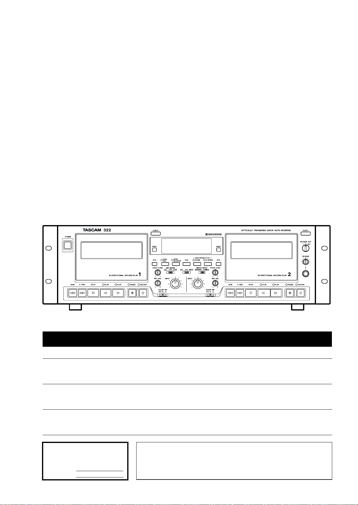
322
Double Auto Reverse Cassette Deck
9101439401
OWNER’S MANUAL
Ü
The lightning flash with arrowhead symbol, within an equilateral triangle, is intended to alert
ÿ
Ÿ
This appliance has a serial number
located on the rear panel. Please record
the model number and serial number
and retain them for your records.
Model number
Serial number
the user to the presence of uninsulated “dangerous voltage” within the product’s enclosure
that may be of sufficient magnitude to constitute a risk of electric shock to persons.
The exclamation point within an equilateral triangle is intended to alert the user to the presence of important operating and maintenance (servicing) instructions in the literature
accompanying the appliance.
CAUTION: TO REDUCE THE RISK OF ELECTRIC SHOCK, DO NOT
REMOVE COVER (OR BACK). NO USER-SERVICEABLE PARTS INSIDE.
REFER SERVICING TO QUALIFIED SERVICE PERSONNEL.
WARNING: TO PREVENT FIRE OR SHOCK
HAZARD, DO NOT EXPOSE THIS
APPLIANCE TO RAIN OR MOISTURE.

Important Safety Precautions
IMPORTANT (for U.K. Customers)
DO NOT cut off the mains plug from this equipment.
If the plug fitted is not suitable for the power points in your home or
the cable is too short to reach a power point, then obtain an
appropriate safety approved extension lead or consult your dealer.
If nonetheless the mains plug is cut off, remove the fuse and
of the plug
inadvertent connection to the mains supply.
If this product is not provided with a mains plug, or one has to be
fitted, then follow the instructions given below:
IMPORTANT: DO NOT make any connection to the larger
terminal which is marked with the letter E or by the safety earth
symbol ç or coloured GREEN or GREEN-and-YELLOW.
The wires in the mains lead on this product are coloured in
accordance with the following code:
As these colours may not correspond with the coloured markings
identifying the terminals in your plug proceed as follows:
The wire which is coloured BLUE must be connected to the terminal
which is marked with the letter N or coloured BLACK.
immediately, to avoid a possible shock hazard by
BLUE : NEUTRAL
BROWN : LIVE
dispose
For U.S.A
TO THE USER
This equipment has been tested and found to
comply with the limits for a Class A digital
device, pursuant to Part 15 of the FCC Rules.
These limits are designed to provide reasonable protection against harmful interference
when the equipment is operated in a commercial environment. This equipment generates,
uses, and can radiate radio frequency energy
and, if not installed and used in accordance with
the instruction manual, may cause harmful
interference to radio communications.
Operation of this equipment in a residental area
is likely to cause harmful interference in which
case the user will be required to correct the
interference at his own expense.
CAUTION
Changes or modifications to this equipment not
expressly approved by TEAC CORPORATION
for compliance could void the user’s authority to
operate this equipment.
The wire which is coloured BROWN must be connected to the
terminal which is marked with the letter L or coloured RED.
When replacing the fuse only a correctly rated approved type should
be used and be sure to re-fit the fuse cover.
IF IN DOUBT — CONSULT A COMPETENT ELECTRICIAN.
For CANADA
AC POWER CORD CONNECTION
CAUTION:
TO PREVENT ELECTRIC SHOCK, MATCH
WIDE BLADE OF PLUG TO WIDE SLOT,
FULLY INSERT.
CORDE DE CONNEXION CA
ATTENTION:
POUR ÉVITER LES CHOCS ÉLECTRIQUES,
INTRODUIRE LA LAME LA PLUS LARGE DE
LA FICHE DANS LA BORNE
CORRESPONDANTE DE LA PRISE ET
POUSSER JUSQU’AU FOND.
2 TASCAM 322
ANTENNA
LEAD IN
WIRE
ANTENNA
DISCHARGE UNIT
(NEC SECTION 810-20)
GROUNDING CONDUCTORS
(NEC SECTION 810-21)
GROUND CLAMPS
POWER SERVICE GROUNDING
ELECTRODE SYSTEM
(NEC ART 250. PART H)
NEC - NATIONAL ELECTRICAL CODE
ELECTRIC
SERVICE
EQUIPMENT
Example of Antenna Grounding as per
National Electrical Code, ANSI/NFPA 70
GROUND
CLAMP
IMPORTANT SAFETY INSTRUCTIONS
CAUTION:
…Read all of these Instructions.
…Save these Instructions for later use.
…Follow all Warnings and Instructions marked on the audio
equipment.
1) Read Instructions — All the safety and operating instructions should
be read before the product is operated.
2) Retain Instructions — The safety and operating instructions should
be retained for future reference.
3) Heed Warnings — All warnings on the product and in the operating
instructions should be adhered to.
4) Follow Instructions — All operating and use instructions should be
followed.
5) Cleaning — Unplug this product from the wall outlet before cleaning.
Do not use liquid cleaners or aerosol cleaners. Use a damp cloth for cleaning.
6) Attachments — Do not use attachments not recommended by the
product manufacturer as they may cause hazards.
7) Water and Moisture — Do not use this product near water — for
example, near a bath tub, wash bowl, kitchen sink, or laundry tub; in a wet
basement; or near a swimming pool; and the like.
8) Accessories — Do not place this product on an unstable cart, stand,
tripod, bracket, or table. The product may fall, causing serious injury to a
child or adult, and serious damage to the product. Use only with a cart,
stand, tripod, bracket, or table recommended by the manufacturer, or sold
with the product. Any mounting of the product should follow the manufacturer’s instructions, and should use a mounting accessory recommended by
the manufacturer.
9) A product and cart combination should be moved with care. Quick stops,
excessive force, and uneven surfaces may cause the product and cart combination to overturn.
10) Ventilation — Slots and openings in the cabinet are provided for ventilation and to ensure reliable operation of the product and to protect it
from overheating, and these openings must not be blocked or covered. The
openings should never be blocked by placing the product on a bed, sofa,
rug, or other similar surface. This product should not be placed in a built-in
installation such as a bookcase or rack unless proper ventilation is provided
or the manufacturer’s instructions have been adhered to.
11) Power Sources — This product should be operated only from the
type of power source indicated on the marking label. If you are not sure of
the type of power supply to your home, consult your product dealer or local
power company. For products intended to operate from battery power, or
other sources, refer to the operating instructions.
12) Grounding or Polarization — This product may be equipped with
a polarized alternating-current line plug (a plug having one blade wider
than the other). This plug will fit into the power outlet only one way. This is
a safety feature. If you are unable to insert the plug fully into the outlet, try
reversing the plug. If the plug should still fail to fit, contact your electrician
to replace your obsolete outlet. Do not defeat the safety purpose of the
polarized plug.
13) Power-Cord Protection — Power-supply cords should be routed so
that they are not likely to be walked on or pinched by items placed upon or
against them, paying particular attention to cords at plugs, convenience
receptacles, and the point where they exit from the product.
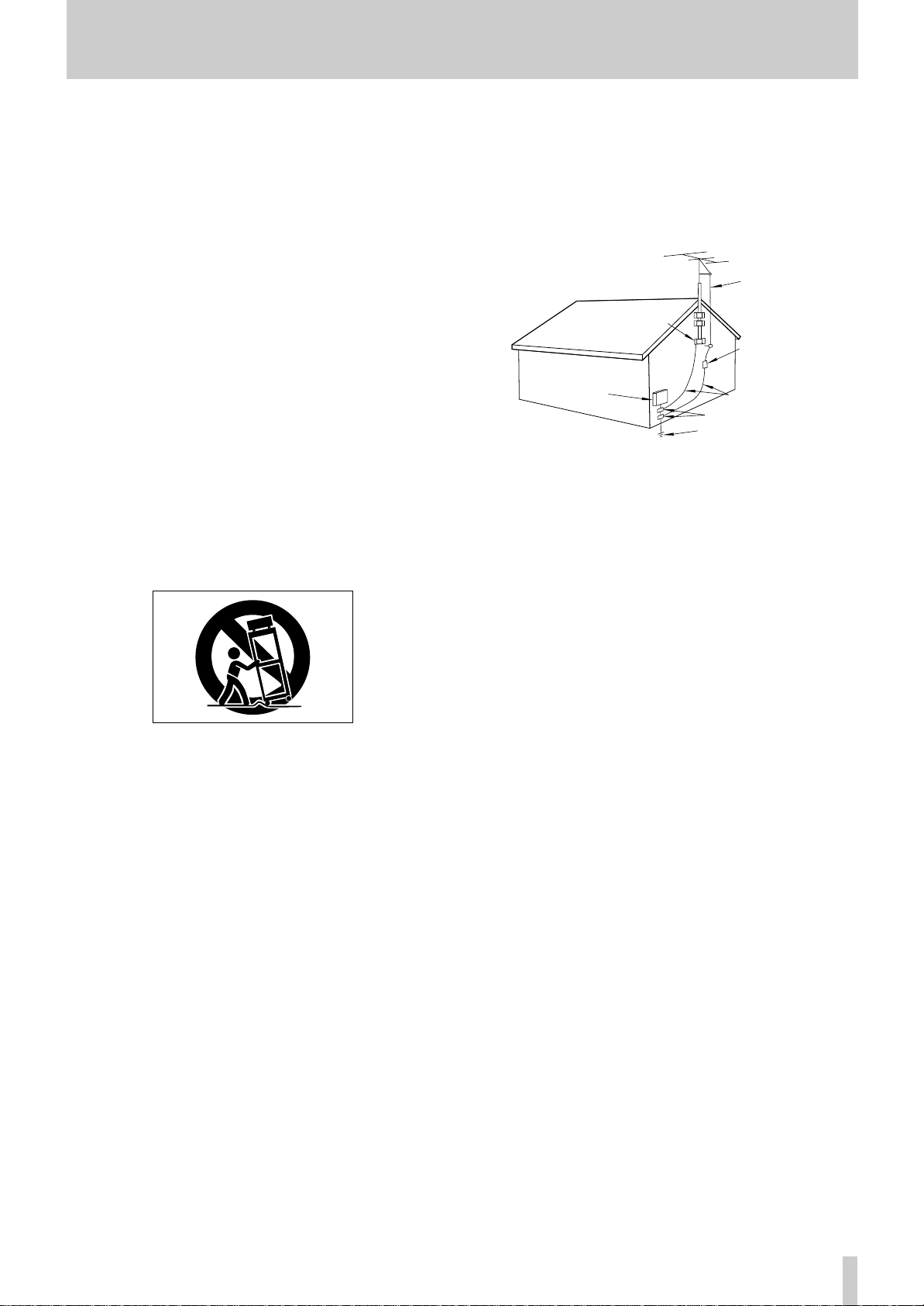
14) Outdoor Antenna Grounding — If an outside antenna or cable
system is connected to the product, be sure the antenna or cable system is
grounded so as to provide some protection against voltage surges and builtup static charges. Article 810 of the National Electrical Code, ANSI/NFPA
70, provides information with regard to proper grounding of the mast and
supporting structure, grounding of the lead-in wire to an antenna discharge
unit, size of grounding conductors, location of antenna-discharge unit, connection to grounding electrodes, and requirements for the grounding electrode.
"Note to CATV system installer:
This reminder is provided to call the CATV system installer’s attention to
Section 820-40 of the NEC which provides guidelines for proper grounding
and, in particular, specifies that the cable ground shall be connected to the
grounding system of the building, as close to the point of cable entry as
practical.
15) Lightning — For added protection for this product during a lightning
storm, or when it is left unattended and unused for long periods of time,
unplug it from the wall outlet and disconnect the antenna or cable system.
This will prevent damage to the product due to lightning and power-line
surges.
16) Power Lines — An outside antenna system should not be located in
the vicinity of overhead power lines or other electric light or power circuits,
or where it can fall into such power lines or circuits. When installing an
outside antenna system, extreme care should be taken to keep from touching such power lines or circuits as contact with them might be fatal.
17) Overloading — Do not overload wall outlets, extension cords, or
integral convenience receptacles as this can result in risk of fire or electric
shock.
18) Object and Liquid Entry — Never push objects of any kind into
this product through openings as they may touch dangerous voltage points
or short-out parts that could result in a fire or electric shock. Never spill
liquid of any kind on the product.
19) Servicing — Do not attempt to service this product yourself as opening or removing covers may expose you to dangerous voltage or other
hazards. Refer all servicing to qualified service personnel.
20) Damage Requiring Service — Unplug this product from the wall
outlet and refer servicing to qualified service personnel under the following
conditions:
a) when the power-supply cord or plug is damaged.
b) if liquid has been spilled, or objects have fallen into the product.
c) if the product has been exposed to rain or water.
d) if the product does not operate normally by following the operating
instructions. Adjust only those controls that are covered by the operating
instructions as an improper adjustment of other controls may result in
damage and will often require extensive work by a qualified technician to
restore the product to its normal operation.
e) if the product has been dropped or damaged in any way.
f ) when the product exhibits a distinct change in performance – this
indicates a need for service.
21) Replacement Parts — When replacement parts are required, be
sure the service technician has used replacement parts specified by the
manufacturer or have the same characteristics as the original part.
Unauthorized substitutions may result in fire, electric shock, or other
hazards.
22) Safety Check — Upon completion of any service or repairs to this
product, ask the service technician to perform safety checks to determine
that the product is in proper operating condition.
23) Wall or Ceiling Mounting — The product should be mounted to a
wall or ceiling only as recommended by the manufacturer.
24) Heat — The product should be situated away from heat sources such
as radiators, heat registers, stoves, or other products (including amplifiers)
that produce heat.
TASCAM 322 3
Before Getting Started
The TASCAM 322 is a double auto reverse cassette
deck primarily designed for continuous playback of
background music or tape dubbing needs. A maximum
of ten 322s can be hooked up to form a sequential play
loop or to synchronize them, with one serving as the
master/source machine and the others serving as the
slave/target machines, for simultaneous tape dubbing.
Table of Contents
General Guide to the Controls and Connectors ....5
Using a Single 322....................................................9
Recording on either deck, or both at the
same time..........................................................9
Continuous recording on both decks....................10
Dubbing from deck 1 onto deck 2 .......................10
Playback...............................................................11
Using just one of the two available decks.......11
Continuous play on both decks.......................11
Using the CPS function........................................12
Erasing recordings................................................12
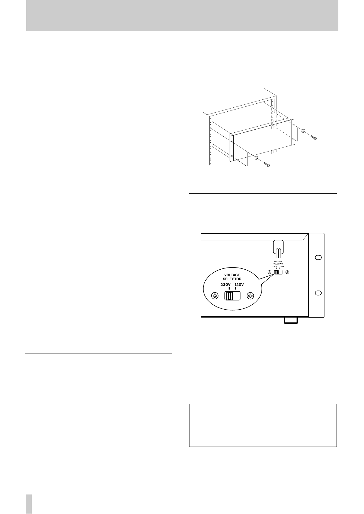
Rack Mounting
The 322 can be installed in a standard 19" rack, using
the provided 4 pairs of screws (M5 x 12) and 4
washers, as shown.
VOLTAGE CONVERSION
NOTE : Voltage conversion is not possible on models
sold in the U.K., Australia or Europe.
Multiple-322 System Operation .............................13
Sequential link play..............................................13
Simultaneous dubbing onto multiple cassettes ....14
Recording an external source onto multiple
cassettes simultaneously .................................15
Care and Maintenance............................................17
Troubleshooting......................................................18
Error Messages.....................................................18
Specifications .........................................................19
Block Diagram.........................................................20
Optional Accessories :
“ LA-322 balanced amplifier kit
“ WR-7000 synchro cable (for interconnecting two or
more 322s, as shown on pp.12 and 13)
“ TZ-261 cleaning kit (except for U.S.A.)
“ HC-1 head cleaner & RC-1 rubber cleaner (U.S.A.
only)
“ Head demagnetizer
Be sure to remove the power cord from the AC outlet
before repositioning the voltage converter switch.
1. Locate the voltage selector on the rear panel.
2. Using a flat-bladed screwdriver, set to the
appropriate 230 V or 120 V position according to
your area.
IN NORTH AMERICA USE ONLY ON 120 V
SUPPLY.
DANS L’AMÉRIOUE DU NORD: UTILISABLE SUR
120 V D’ALIMENTATION UNIQUEMENT.
4 TASCAM 322
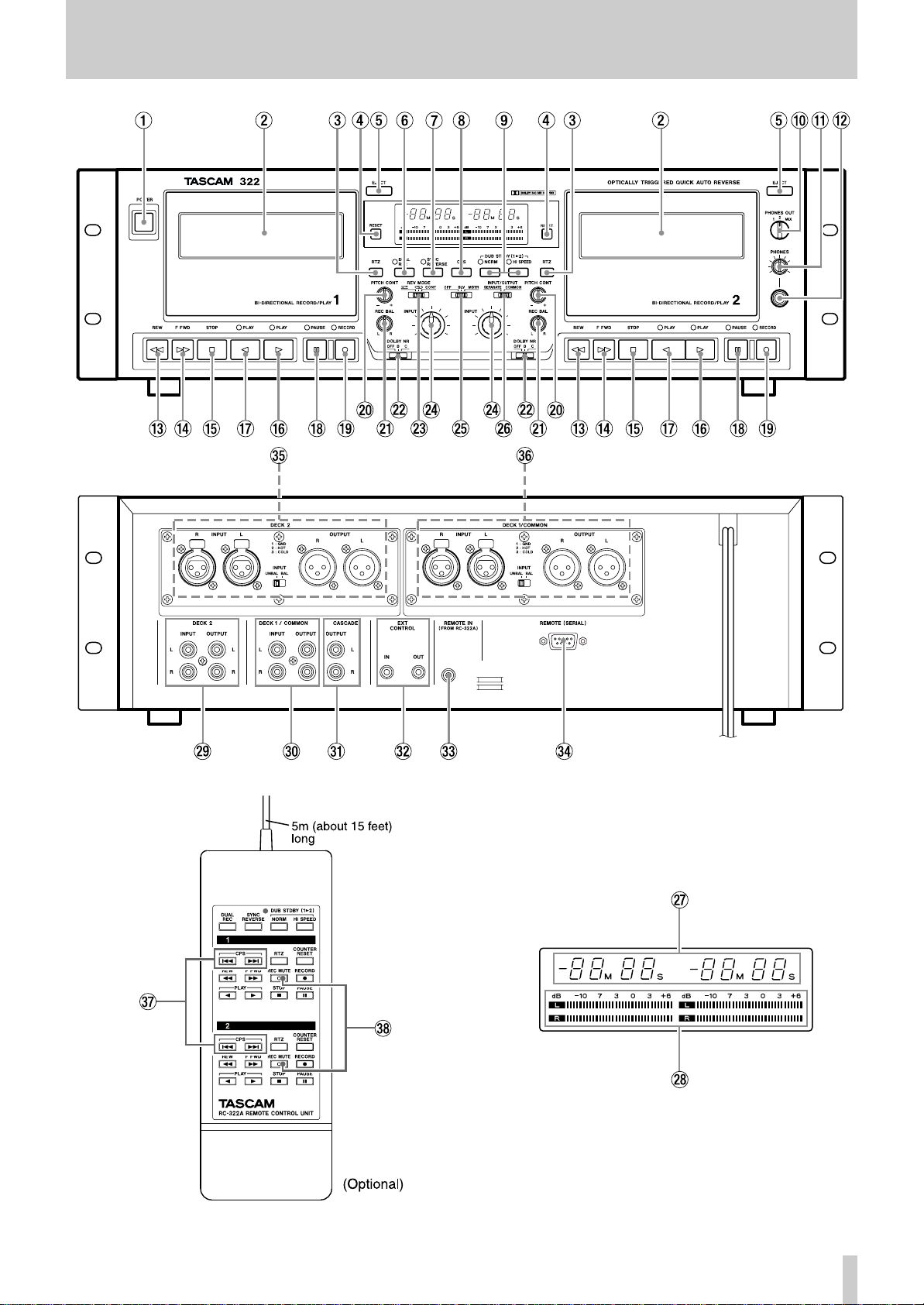
General Guide to the Controls and Connectors
TASCAM 322 5

General Guide to the Controls and Connectors
Front Panel
1 POWER switch : Turns the unit on and off.
NOTE
The equipment draws nominal nonoperating power
from the ACoutlet with its POWER switch in the OFF
position.
2 Cassette Compartment : Opens upon pressing
the EJECT button.
3 RTZ (Return-To-Zero) button : Fast-winds the
tape to a zero reference point selected by pressing
RESET. You can press PLAY after RTZ for the tape
to automatically start playing at the end of the
search function. If PAUSE is pressed instead of
PLAY, the deck goes into Play Ready mode.
The tape will go slightly past the 0000 point on the
counter because of inertia.
RTZ cannot operate unless it is pressed when the
tape counter reads 0003 or higher numbers.
4 RESET button : Resets the counter to 0000 to
mark any point on the tape which you can access by
pressing RTZ.
5 EJECT button : Opens the cassette compartment.
deck 2, or MIX for monitoring a mix of two tape
signals. During Record Ready or Record modes,
you can monitor input signals, as selected with this
switch.
B PHONES control : Adjusts the listening level of
the headphones plugged into the PHONES jack.
C PHONES jack : For connection to 3-conductor
stereo headphones.
D REW button : Winds the tape at high speed in
reverse. When pressed while in Play Ready mode,
offers cueing to an earlier point.
E F FWD button : Winds the tape at high speed in
the forward direction. When pressed while in Play
Ready mode, offers forward cueing.
F STOP button : Used to stop the tape and exit the
current operation modes.
G Forward PLAY ( Á ) button : plays the forward
side of the tape. The associated LED blinks during
Stop, and lights steadily during Play Ready and
Play. If pressed when the tape is ready for record or
play on the reverse side, switches the tape to be
ready for record or play on the forward side.
6 DUAL REC button : If pressed when the tape is
stopped, puts both decks into Record Ready mode ;
and pressing PLAY on either deck starts recording
via deck l’s input. This function is used only for
single 322 operation.
7 SYNC REVERSE switch : Used for tape
dubbing, causing two or more tapes to be switched
to their reverse sides in synchronization with each
other.
8 CPS switch : Can be operated while in Stop, Play
Ready, and Play modes to access specific programs
on the tape.
9 DUB STDBY switches : In NORM mode, you
can locate the source tape to the point you want to
next start dubbing from, while keeping the target
tapes waiting at the end of the previous recording.
You can’t do this in HI SPEED mode.
A PHONES OUT switch : Selects a headphone
monitor source. Set to 1 for monitoring tape signals
from deck 1, 2 for monitoring tape signals from
H Reverse PLAY ( Ó ) button : Similar to the
forward play button, but plays the reverse side of
the tape or switches the tape to be ready for record
or play on the reverse side.
I PAUSE button : Interrupts record or play. If
pressed when the tape is stopped, puts the deck into
Play Ready mode. If pressed while holding down
RECORD, puts the deck into Record Ready mode.
Recording starts upon pressing PLAY-the
associated LED of which is lit.
J RECORD button : Holding down this button and
pressing PLAY starts recording. Pressing STOP
while holding down RECORD records a 4–second
silence.
K PITCH CONT knob : Varies play speed about
+/–l0 % to match pitch or to produce special
effects. For normal play operation, be sure to set
this knob to the center position.
L REC BAL knob : Used to balance the left and
right input levels.
6 TASCAM 322
 Loading...