


ST.TM.E10076.3
Issue 3
ENGLISH (UK)
INSTRUCTION MANUAL
E5714/E5740-xxx DSNG, E5715/E5750
DENG Voyager Encoder
Build Version 2.1.0 to 3.1.0 (and later)
M2/VOY/E5714, M2/VOY/E5740-xxx, M2/VOY/E5715, M2/VOY/E5750 and Options

Preliminary Pages
ENGLISH (UK)
READ THIS FIRST!
If you do not understand the contents of this manual
DO NOT OPERATE THIS EQUIPMENT.
Also, translation into any EC official language of this manual can be made available, at your cost.
ITALIANO
LEGGERE QUESTO AVVISO PER PRIMO!
Se non si capisce il contenuto del presente manuale
NON UTILIZZARE L’APPARECCHIATURA.
È anche disponibile la versione italiana di questo manuale, ma il costo è a carico dell’utente.
SVENSKA
LÄS DETTA FÖRST!
Om Ni inte förstår informationen i denna handbok
ARBETA DÅ INTE MED DENNA UTRUSTNING.
En översättning till detta språk av denna handbok kan också anskaffas, på Er bekostnad.
NEDERLANDS
LEES DIT EERST!
Als u de inhoud van deze handleiding niet begrijpt STEL DEZE APPARATUUR DAN NIET IN WERKING.
U kunt tevens, op eigen kosten, een vertaling van deze handleiding krijgen.
PORTUGUÊS |
SUOMI |
LEIA O TEXTO ABAIXO ANTES DE MAIS NADA! |
LUE ENNEN KÄYTTÖÄ! |
Se não compreende o texto deste manual
NÃO UTILIZE O EQUIPAMENTO.
O utilizador poderá também obter uma tradução do manual para o português à própria custa.
Jos et ymmärrä käsikirjan sisältöä ÄLÄ KÄYTÄ LAITETTA.
Käsikirja voidaan myös suomentaa asiakkaan kustannuksella.
FRANÇAIS
AVANT TOUT, LISEZ CE QUI SUIT!
Si vous ne comprenez pas les instructions contenues dans ce manuel NE FAITES PAS FONCTIONNER CET APPAREIL.
En outre, nous pouvons vous proposer, à vos frais, une version française de ce manuel.
DANSK
LÆS DETTE FØRST!
Udstyret må ikke betjenes
MEDMINDRE DE TIL FULDE FORSTÅR INDHOLDET AF DENNE
HÅNDBOG.
Vi kan også for Deres regning levere en dansk oversættelse af denne håndbog.
DEUTSCH
LESEN SIE ZUERST DIESEN HINWEIS!
Sollte Ihnen der Inhalf dieses Handbuches nicht klar verständlich sein, dann
BEDIENEN SIE DIESE GERÄTE NICHT!
Eine Übersetzung des Handbuches in diese Sprache ist gegen Berechnung lieferbar.
ΕΛΛΗΝΙΚΑ
ÄΙΑΒΑΣΤΕ ΠΡÙΤΑ ΑΥΤΟ!
Αν δεν καταλÜβετε το περιεχüìενο αυτοý του βοηθÞìατοò/εγχειριδßου ΜΗΝ ΛΕΙΤΟΥΡΓΗΣΕΤΕ ΑΥΤΟΝ ΤΟΝ ΕΞΟΠΛΙΣΜΟ.
Επßσηò, αυτü το εγχειρßδιο εßναι διαθÝσιìο σε ìετÜφραση σε αυτÞ τη γλþσσα και ìπορεßτε να το αγορÜσετε.
ESPAÑOL
LEA ESTE AVISO PRIMERO!
Si no entiende el contenido de este manual
NO OPERE ESTE EQUIPO.
Podemos asimismo suministrarle una traducción de este manual al (idioma) previo pago de una cantidad adicional que deberá abonar usted mismo.
This document and the information contained in it is the property of TANDBERG Television Ltd and may be the subject of patents pending and granted. It must not be used for commercial purposes nor copied, disclosed, reproduced, stored in a retrieval system or transmitted in any form or by any means (electronic, mechanical, photocopying, recording or otherwise), whether in whole or in part, without TANDBERG Television’s prior written agreement.
2001 - 2002 TANDBERG Television Ltd. All rights reserved.
Issue 3 first published in 2002 by:
TANDBERG TELEVISION LTD
REGISTERED ADDRESS:
UNIT 2 STRATEGIC PARK,
COMINES WAY,
HEDGE END, SOUTHAMPTON,
HAMPSHIRE,
SO30 4DA
Registered Company Number 03695535
Page ii |
Instruction Manual: evolution 5000 E57xx DSNG and DENG Voyager Encoder |
|
ST.TM.E10076.3 |

Preliminary Pages
List of Contents
Chapter 1: Introduction to the Basic Encoder
Gives a general description of the equipment and its main features and functions. Identifies the controls, indicators and connectors on the front and rear panels.
Chapter 2: Installing the Equipment
Provides a guide to the suitability of an installation and gives detailed procedures for the preparation and installation of the equipment. Also details the external connectors and provides important safety information.
Chapter 3: Options and Upgrades
This chapter describes the options and upgrades available for the E57xx series of Encoder models.
Chapter 4: Operating the Equipment Locally
Describes local control in detail. Provides the power-up/power-down procedures and other general operating/control/set-up procedures.
Chapter 5: Web Browser Interface
Details how to access and use the Web Browser Interface for a range of diagnostic and other utilities.
Chapter 6: Preventive Maintenance and Fault-finding
Details routine maintenance tasks to be performed by the operator and provides general servicing advice and fault-finding information. Provides information regarding warranty and maintenance available from Customer Services. Gives relevant disposal information.
Annex A: Glossary
Annex B: Technical Specification
Annex C: Predefined User Configurations
Annex D: Language Abbreviations
Annex E: Creating and Downloading a Logo
Annex F: Band Plans
Annex G: Audio Modes
Annex H: Error Messages
Annex I: Accuracy of Frequency Sources
Annex J: Use of Remux Card in ATSC
Annex K: EDH Capability for E57xx Encoders
Indexes
Instruction Manual: evolution 5000 E57xx DSNG and DENG Voyager Encoder |
Page iii |
ST.TM.E10076.3 |
|

Preliminary Pages
About this Manual
This manual provides instructions and information for the installation, operation of the Encoder.
This manual should be kept in a safe place for reference for the life of the equipment. It is not intended that this manual will be amended by the issue of individual pages. Any revision will be by a complete reissue. Further copies of this manual can be ordered from the address shown on page viii. If passing the equipment to a third party, also pass the relevant documentation.
Issues of this manual are listed below:
Issue |
Date |
Build Version |
Comments |
|
|
|
|
1 |
Dec 2000 |
2.1.0 – 2.2.0 |
E5714/E5740 initial release. |
|
|
|
|
2 |
Sept 2002 |
2.1.0 – 3.0.0 |
Update for 3.0.0. |
|
|
|
|
2 |
Dec 2002 |
2.1.0 – 3.1.0 |
Update for 3.1.0. New option modules added. |
|
|
|
|
NOTE…
The Build Version in the table refers to an overall number which encompasses all the various software/firmware versions of video, audio, etc in the Encoder.
The following manuals are also associated with this equipment:
ST.TS.SNMP.E10074: |
Simple Network Management Protocol |
ST.TS.E10074 |
Remote Control Protocol |
ST.AN.1094: |
Video Noise Reduction and Compression |
ST.AN.1110: |
Near Loss-less MPEG Concatenation |
|
Without Helper Signals |
ST.AN.BW.E10074: |
Variable Bandwidth Feature of E57xx |
|
Encoders |
Nomenclature
The terms RS-232 and RS-422 have been superseded by EIA-232 and EIA-422. However, because the original names are inscribed on the Encoder the original terms are used in the text of this manual.
Page iv |
Instruction Manual: evolution 5000 E57xx DSNG and DENG Voyager Encoder |
|
ST.TM.E10076.3 |

Preliminary Pages
Acknowledgements
General
All best endeavours have been made to acknowledge registered trademarks and trademarks used throughout this manual. Any notified omissions will be rectified in the next issue of this manual. Some trademarks may be registered in some countries but not in others.
Registered trademarks and trademarks used are acknowledged below and marked with their respective symbols. However, they are not marked within the text of this manual.
Registered Trademarks
AC-3®, Dolby Digital® and Pro Logic® are registered trademarks of Dolby Laboratories Licensing Corporation.
Musicam® is a registered trademark of Thomson and Télédiffusion de France (TDF), Europe, and is a registered trademark of CCS (now Musicam USA Incorporated), USA.
Ethernet® is a registered trademark of Xerox Corporation. XILINX® is a registered trademark of Xilinx Inc.
Trademarks
Pozidriv™ is a trademark of European Industrial Services. Reflex™ is a trademark of TANDBERG Television. Windows NT™ is a trademark of Microsoft Corporation. STREAMS™ is a trademark of TANDBERG Television. NDS™ is a trademark of NDS Limited.
Instruction Manual: evolution 5000 E57xx DSNG and DENG Voyager Encoder |
Page v |
ST.TM.E10076.3 |
|

Preliminary Pages
Warnings, Cautions and Notes
Heed Warnings
All warnings on the product and in the operating instructions should be adhered to. The manufacturer can not be held responsible for injuries or damage where warnings and cautions have been ignored or taken lightly.
Read Instructions
All the safety and operating instructions should be read before this product is operated.
Follow Instructions
All operating and use instructions should be followed.
Retain Instructions
The safety and operating instructions should be retained for future reference.
WARNINGS...
WARNINGS GIVE INFORMATION WHICH, IF STRICTLY OBSERVED, WILL PREVENT PERSONAL INJURY OR DEATH, OR DAMAGE TO PERSONAL PROPERTY OR THE ENVIRONMENT. THEY ARE BOXED AND SHADED FOR EMPHASIS, AS IN THIS EXAMPLE, AND ARE PLACED IMMEDIATELY PRECEDING THE POINT AT WHICH THE READER REQUIRES THEM.
CAUTIONS...
Cautions give information which, if strictly followed, will prevent damage to equipment or other goods. They are boxed for emphasis, as in this example, and are placed immediately preceding the point at which the reader requires them.
NOTES...
Notes provide supplementary information. They are highlighted for emphasis, as in this example, and are placed immediately after the relevant text.
EMC Compliance
This equipment is certified to the EMC requirements detailed in Annex B, Technical Specification. To maintain this certification, only use the leads supplied or if in doubt contact Customer Services.
Page vi |
Instruction Manual: evolution 5000 E57xx DSNG and DENG Voyager Encoder |
|
ST.TM.E10076.3 |

Preliminary Pages
Contact Information
TANDBERG Television Customer Services
Support Services
Our primary objective is to provide first class customer care that is tailored to your specific business and operational requirements. All levels are supported by one or more service performance reviews to ensure the perfect partnership between TANDBERG Television and your business.
Warranty
All TANDBERG Products and Systems are designed and built to the highest standards and are covered under a comprehensive 12 month warranty.
Levels of Continuing TANDBERG Television Service Support
For stand-alone equipment, then TANDBERG Television BASIC Advantage is the value for money choice for you. BASIC provides you with year-by-year Service long after the warranty has expired.
For systems support you can choose either Gold or Silver Advantage. These packages are designed to save you costs and protect your income through enlisting the help of TANDBERG Television support specialists.
VOYAGER Advantage is the truly mobile service solution. This provides a package specifically designed to keep you mobile and operational.
Call TANDBERG Sales for more details.
Where to Find Us
Europe, Middle East |
+44 (0) 23 8048 4455 |
and Africa: |
Fax: +44 (0) 23 8048 4467 |
|
fieldservice@tandbergtv.com |
Americas: |
+1 (321) 308 0470 |
|
fieldservice-americas@tandbergtv.com |
China: |
+86 10 6539 1109 (Beijing) |
|
+852 2530 3215 (Hong Kong) |
|
fieldservice-asia@tandbergtv.com |
Australia/NZ: |
+612 9360 2053 |
|
fieldservice-australia@tandbergtv.com |
Internet Address: |
http://www.tandbergtv.com |
Instruction Manual: evolution 5000 E57xx DSNG and DENG Voyager Encoder |
Page vii |
ST.TM.E10076.3 |
|

Preliminary Pages
Technical Training
Training Courses
TANDBERG Television provides a wide range of training courses on the operation and maintenance of our products and on their supporting technologies. TANDBERG can provide both regularly scheduled courses and training tailored to individual needs. Courses can be run either at your premises or at one of our dedicated training facilities.
Where to Find Us
For further information on TANDBERG Television's training programme please contact us:
International Telephone: |
+44 23 8048 4229 |
International Facsimile |
+44 23 8048 4467 |
E-mail Address: |
training@tandbergtv.com |
Internet Address |
http://www.tandbergtv.com |
Customer Services and Technical Training Postal Address
Tandberg Television
Unit 2
Strategic Park
Comines Way
Hedge End
Southampton
Hampshire
SO30 4DA
United Kingdom
Return of Equipment
If you need to return equipment for repair, please contact the Customer Services Helpdesk on +44 (0) 23 8048 4455. A Returns Authorisation Number (RAN) will be issued and full details of the unit will be logged. Please ensure the RAN number is clearly marked on the packaging of the unit. The unit should then be sent to the following address:
Tandberg Television – Customer Services Unit 1
Strategic Park
Comines Way Hedge End Southampton Hampshire SO30 4DA United Kingdom
Technical Publications
If you need to contact TANDBERG Television Technical Publications regarding this publication, e-mail: techpubs@tandbergtv.com.
Page viii |
Instruction Manual: evolution 5000 E57xx DSNG and DENG Voyager Encoder |
|
ST.TM.E10076.3 |

Chapter 1
Introduction to the Basic Encoder
Contents
1.1 Scope of this Manual................................................. |
1-3 |
|
1.1.1 |
Who Should Use This Manual ...................... |
1-3 |
1.1.2 |
Build Version................................................. |
1-3 |
1.1.3What Equipment is Covered by This
|
Manual.......................................................... |
1-3 |
|
Equipment Models........................................ |
1-3 |
|
Information Label.......................................... |
1-5 |
|
Hardware Configuration................................ |
1-5 |
|
Build Revision ............................................... |
1-5 |
1.2 Role of the Encoder in a System............................... |
1-5 |
|
1.2.1 |
Typical System ............................................. |
1-5 |
1.2.2 |
DSNG Systems............................................. |
1-6 |
|
Overview....................................................... |
1-6 |
|
E5714 ........................................................... |
1-7 |
|
E5740/E5760................................................ |
1-7 |
1.2.3 |
DENG Systems............................................. |
1-7 |
1.3 Summary of Features................................................ |
1-8 |
|
1.3.1 |
Video Encoding............................................. |
1-8 |
|
MPEG-2 Encoding ........................................ |
1-8 |
|
Video Encoding Modes................................. |
1-8 |
|
Video Inputs.................................................. |
1-8 |
|
Video Input Types......................................... |
1-8 |
|
Serial Digital Video Input Error Detection |
|
|
and Handling (EDH)...................................... |
1-8 |
|
Video Encoding Functions ............................ |
1-8 |
|
Motion Estimation ......................................... |
1-9 |
|
Variable Video Bit-rate.................................. |
1-9 |
|
Coding Resolutions....................................... |
1-9 |
|
Internal Frame Synchroniser ...................... |
1-10 |
|
Output on Video Loss ................................. |
1-10 |
1.3.2 |
Audio Encoding........................................... |
1-10 |
General ....................................................... |
1-10 |
Audio Inputs ................................................ |
1-11 |
Audio Channels........................................... |
1-11 |
MPEG Encoding Modes.............................. |
1-11 |
Dolby Digital (AC-3) Encoding Modes......... |
1-11 |
Test Tones .................................................. |
1-12 |
Audio Variable Bit-rate ................................ |
1-12 |
Dolby Digital (AC-3) .................................... |
1-12 |
1.3.3Vertical Blanking Interval (VBI) Line
|
Processing Modes....................................... |
1-13 |
|
Introduction ................................................. |
1-13 |
|
VBI in Picture .............................................. |
1-13 |
|
VBI User Data ............................................. |
1-14 |
|
VBI in PID.................................................... |
1-14 |
|
Teletext Extraction ...................................... |
1-14 |
1.3.4 |
Data Channels ............................................ |
1-14 |
1.3.5 |
Outputs........................................................ |
1-15 |
1.3.6 |
IF Modulation .............................................. |
1-15 |
|
E5714.......................................................... |
1-15 |
|
E5740.......................................................... |
1-15 |
|
E5715/E5750 .............................................. |
1-15 |
1.3.7 |
Control and Monitoring................................ |
1-15 |
1.3.8 |
Options and Upgrades ................................ |
1-15 |
1.4 Guided Tour............................................................. |
1-16 |
|
1.4.1 |
Enclosure .................................................... |
1-16 |
1.4.2 |
The User Interface ...................................... |
1-16 |
1.4.3 |
Front Panel Description............................... |
1-16 |
|
Front Panel Display, Navigation Keys, |
|
|
Softkeys, Keyboard ..................................... |
1-16 |
|
Power Supply Stand-by Switch ................... |
1-17 |
1.4.4 |
Rear Panel Description ............................... |
1-17 |
|
Introduction ................................................. |
1-17 |
Instruction Manual: evolution 5000 E57xx DSNG and DENG Voyager Encoder |
Page 1-1 |
ST.TM.E10076.3 |
|

Introduction to the Basic Encoder
1U Chassis.................................................. |
1-18 |
List of Tables |
|
|
2U Chassis.................................................. |
1-18 |
Table 1.1: Build Version ................................................................ |
1-3 |
|
1.4.5 Boards in the Basic Encoder....................... |
1-19 |
Table 1.2: Equipment Model Descriptions..................................... |
1-4 |
|
List of Figures |
|
Table 1.3: Video Bit-rate Range ................................................... |
1-9 |
|
|
Table 1.4: Video Coding Resolutions |
1-10 |
||
Figure 1.1: 1U Encoder Front View |
1-4 |
|||
Table 1.5: MPEG-1 Audio Encoding Bit-rates |
1-12 |
|||
Figure 1.2: 2U Encoder Front View |
1-4 |
|||
Table 1.6: Dolby Digital Audio Encoding Bit-rates |
1-13 |
|||
Figure 1.3: Information Label 1 |
1-5 |
|||
Table 1.7: Front Panel Indicators |
1-16 |
|||
Figure 1.4: Information Label 2 |
1-5 |
|||
Table 1.8: Boards in the Basic Encoder |
1-19 |
|||
Figure 1.5: Typical DSNG Encoder Configuration |
1-6 |
|||
|
|
|||
Figure 1.6: Typical DENG System Configuration ........................... |
1-7 |
|
|
|
Figure 1.7: 1U Encoder Front Panel Indicators ............................ |
1-16 |
|
|
|
Figure 1.8: Stand-by Switch ......................................................... |
1-17 |
|
|
|
Figure 1.9: 2U Encoder Front Panel Indicators ............................ |
1-17 |
|
|
|
Figure 1.10: E5714 (1U) Rear Panel Component Parts and |
|
|
|
|
Connectors.................................................................. |
1-18 |
|
|
|
Figure 1.11: E5715 (1U) Rear Panel Component Parts and |
|
|
|
|
Connectors.................................................................. |
1-18 |
|
|
|
Figure 1.12: E5740 (2U) Rear Panel Component Parts and |
|
|
|
|
Connectors.................................................................. |
1-18 |
|
|
|
Figure 1.13: E5750 (2U) Rear Panel Component Parts and |
|
|
|
|
Connectors.................................................................. |
1-19 |
|
|
Page 1-2 |
Instruction Manual: evolution 5000 E57xx DSNG and DENG Voyager Encoder |
|
ST.TM.E10076.3 |
Introduction to the Basic Encoder
1.1Scope of this Manual
1.1.1Who Should Use This Manual
This manual is written for operators/users of the 1U and 2U Voyager Encoders to assist in the installation, operation and day-to-day care. These Encoders are referred to throughout this manual as ‘Encoder(s)’ unless there is a specific difference, where they will be referred to by the model number.
WARNING…
DO NOT REMOVE THE COVERS OF THIS EQUIPMENT. HAZARDOUS VOLTAGES ARE PRESENT WITHIN THIS EQUIPMENT AND MAY BE EXPOSED IF THE COVERS ARE REMOVED. ONLY TANDBERG TELEVISION TRAINED AND APPROVED SERVICE ENGINEERS ARE PERMITTED TO SERVICE THIS EQUIPMENT.
CAUTION…
Unauthorised maintenance or the use of non-approved replacements may affect the equipment specification and invalidate any warranties.
This manual does not include any maintenance information or procedures which would require the removal of covers.
1.1.2Build Version
This manual has been written to cover the functionality in Table 1.1.
Table 1.1: Build Version
|
E5714, E5740, E5715, E5750 |
|
|
Build Version |
2.1.0 – 3.1.0 and later |
|
|
The Build version indicates the status of the Encoder and refers to an overall number which encompasses all the various software/firmware versions of video, audio, etc. in the basic Encoder.
The current Build version can be found in the Build Menu (see Chapter 4, Operating the Equipment Locally, Figure 4.9). This number should be quoted in all correspondence with TANDBERG Television.
This manual continues to be relevant to subsequent Build versions where the functionality of the equipment has not changed. When a new issue of the Build version changes the functionality, a new issue of this manual is provided.
1.1.3What Equipment is Covered by This Manual
Equipment Models
Each model of Encoder comprises an enclosure with a Base Board and Modulator fitted as standard. The E5714 and E5740 are fitted with a Satellite Modulator; the E5715 and E5750 are fitted with an OFDM Modulator.
Instruction Manual: evolution 5000 E57xx DSNG and DENG Voyager Encoder |
Page 1-3 |
ST.TM.E10076.3 |
|

Introduction to the Basic Encoder
There are vacant slots for option modules; one in the E5714 and E5715; three in the E5760; four in the E5740; five in the E5750. These slots can be occupied by any combinations of modules shown in Chapter 3, Options and Upgrades.
Figure 1.1: 1U Encoder Front View
Figure 1.2: 2U Encoder Front View
No options need be fitted but any slot not occupied by an option module must have a blank module or blanking plate fitted (see Chapter 3, Options and Upgrades).
The marketing codes, part numbers and model numbers of the basic units are shown in Table 1.2, those of the option modules in Chapter 3, Options and Upgrades.
Table 1.2: Equipment Model Descriptions
Model |
Part |
Marketing |
Description |
Number |
Number |
Code |
|
|
|
|
|
E5714 Encoder |
E10110 |
M2/VOY/E5714 |
1U MPEG-2 DSNG Encoder with QPSK modulator. Has |
|
|
|
4:2:0/4:2:21 video encoding mode and fully exhaustive motion |
|
|
|
estimation. |
E5715 Encoder |
E10111 |
M2/VOY/E5715 |
1U MPEG-2 DENG Encoder with OFDM modulator. Has |
|
|
|
4:2:0/4:2:21 video encoding mode and fully exhaustive motion |
|
|
|
estimation. |
E5740 Encoder |
E10076 |
M2/VOY/E5740 |
2U MPEG-2 DSNG Encoder with IF output satellite |
|
|
|
modulator. Has 4:2:0/4:2:21 video encoding mode and fully |
|
|
|
exhaustive motion estimation. |
E5740 Encoder |
E10122 |
M2/VOY/E5740- |
12 to 36 V dc powered 2U MPEG-2 DSNG Encoder with IF |
|
|
IF/12-36V |
output satellite modulator. Has 4:2:0/4:2:21 video encoding |
|
|
|
mode and fully exhaustive motion estimation. |
E5740 Encoder |
E10130 |
M2/VOY/E5740- |
2U MPEG-2 DSNG Encoder with L-band output satellite |
|
|
LBAND |
modulator. Has 4:2:0/4:2:21 video encoding mode and fully |
|
|
|
exhaustive motion estimation. |
E5740 Encoder |
E10131 |
M2/VOY/E5740- |
12 to 36 V dc powered 2U MPEG-2 DSNG Encoder with |
|
|
LBAND/12-36V |
L-band output satellite modulator. Has 4:2:0/4:2:21 video |
|
|
|
encoding mode and fully exhaustive motion estimation. |
E5750 Encoder |
E10078 |
M2/VOY/E5750 |
2U MPEG-2 DENG Encoder with OFDM modulator. Has |
|
|
|
4:2:0/4:2:21 video encoding mode and fully exhaustive motion |
|
|
|
estimation. |
1 4:2:2 is only available when software option M2/ESO2/422 is purchased.
Page 1-4 |
Instruction Manual: evolution 5000 E57xx DSNG and DENG Voyager Encoder |
|
ST.TM.E10076.3 |

Introduction to the Basic Encoder
Information Label
There are two information labels which identify the configuration of the unit. Figure 1.3 and Figure 1.4 are typical examples.
Serial Number |
Encoder |
|
|
Serial No. NNN |
|
||
A unique number for unit identification |
|
||
|
E10076_XX _XX _XX _XX_XX_XX |
|
|
|
M2/VOY/E5740 |
|
|
|
|
|
|
|
|
|
|
Hardware Configuration
A reference which identifies each piece of hardware in the equipment
Marketing Code
A code which identifies the product for marketing purposes
Figure 1.3: Information Label 1
|
|
|
Evolution 5000 Encoder |
|
|
|
|
|
|
|
|
Bar Code |
|
Serial No. NNN |
|
||
|
|
|
|
||
Used for unit identification in the |
|
|
|
|
|
|
|
|
|
|
|
manufacturing process |
E10076_XX _XX _XX _XX_XX_XX |
|
|||
|
|
|
M2/VOY/E5740 |
|
|
|
|
|
|
|
|
Product Name
A name which identifies the type of product.
Figure 1.4: Information Label 2
Hardware Configuration
Each piece of hardware has a specific reference number. These are linked to give a hardware configuration number (see Figure 1.3) for the whole unit. The first part of the number refers to the enclosure and any modules forming part of the basic unit, and each subsequent part of the number refers to an option module. Refer to Chapter 3, Options and Upgrades for the possible positions of each option module.
Build Revision
The build revision refers to the physical status of the enclosure and any option modules at the time the equipment was shipped from the factory. It is NOT the same as the Build version, which relates to software and firmware.
1.2Role of the Encoder in a System
1.2.1Typical System
The Encoder is a transportable digital exciter designed specifically for mobile contribution applications. It is compact and lightweight, fully MPEG-2 and DVB or ATSC compliant and has high performance for the transmission of studio-quality video material. The equipment is designed to be suitable for both flyaway use (within an appropriate flight case) and truck installation.
Instruction Manual: evolution 5000 E57xx DSNG and DENG Voyager Encoder |
Page 1-5 |
ST.TM.E10076.3 |
|
Introduction to the Basic Encoder
The E5714 and E5740 contain the same high performance encoder. The E5714 is a 1U chassis housing the encoder and a QPSK satellite modulator. The E5740 is a 2U chassis housing the encoder, and a satellite modulator capable of QPSK, 8PSK2 and 16QAM3 modulation.
The Encoder has one card, containing a single video encoder, two stereo audio encoders (dual standard MPEG-1 (layer 2)/Dolby Digital (AC-3)4), composite video decoder, CA5, data input and general purpose VBI extraction and encoding circuitry. It also contains either a satellite modulator or an OFDM modulator.
High quality 4:2:0 or 4:2:26 video encoding is ensured by the inclusion of digital noise reduction techniques7 and many other proprietary algorithms as well as standard MPEG compression techniques. Fully Exhaustive motion estimation is also used.
Video can be input to the unit in serial digital component (SDI) format or composite analogue (PAL/NTSC). There is also a logo overlay facility allowing broadcasters to trademark material.
The audio functionality supports multiple sampling frequencies, bit-rates and coding modes. Audio can be input in balanced analogue, digital AES/EBU input as a discrete channel or embedded on serial digital video. Various coding standards are supported, including Linear PCM. Additional audio channels can be accommodated by purchasing the option module M2/EOM2/AUDLIN.
Unit functionality can be further extended with option modules (see
Chapter 3, Options and Upgrades).
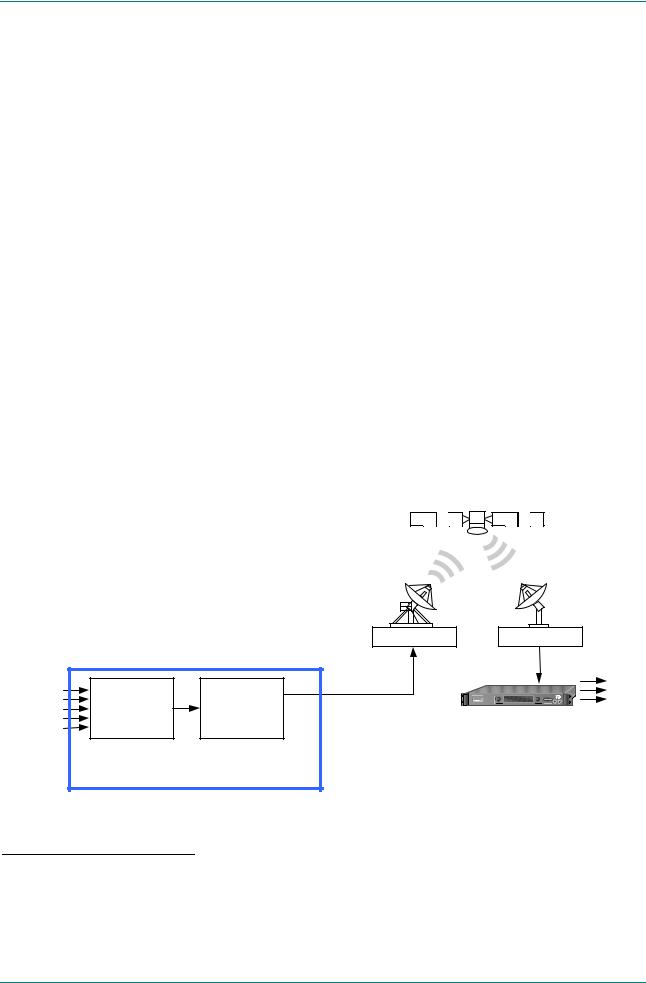
1.2.2DSNG Systems
Overview
Up-link equipment |
|
(including Up-converter |
Down-link equipment |
and High Power |
(including Low Noise Block |
Amplifier) |
and Down-converter) |
Tx |
Rx |
VIDEO (ANALOGUE) VIDEO (DIGITAL)
AUDIO SYNC DATA ASYNC DATA
Encoder |
Modulator |
|
DSNG Encoder |
IF
Alteia
Satellite Receiver
VIDEO
AUDIO ASYNC DATA  SYNC DATA
Figure 1.5: Typical DSNG Encoder Configuration
28PSK is only available when software option M2/ESO2/SM38PSK is purchased.
316QAM is only available when software option M2/ESO2/SM316QAM is purchased.
4Dolby Digital (AC-3) is only available when software option M2/ESO2/AC3 is purchased.
5CA relates to RAS and BISS. RAS and BISS are only available when software options M2/ESO2/RAS and M2/EDCOM2/BISS are purchased. A E57xx Encoder may be fitted with both RAS and BISS options but only one scrambling format can be used at any one time. BISS is available from Build version 2.1.0 but BISSis not supported before Build version 2.2.0.
64:2:2 is only available when software option M2/ESO2/422 is purchased.
7Noise reduction is only available when software option M2/ESO2/NR is purchased.
Page 1-6 |
Instruction Manual: evolution 5000 E57xx DSNG and DENG Voyager Encoder |
|
ST.TM.E10076.3 |
Introduction to the Basic Encoder
E5714
The satellite modulator within the E5714 supports QPSK modulation in accordance with EN 300 421 (DVB-S). It provides a main and monitoring IF Output. The IF frequency can be tuned between 50 MHz and 90 MHz.
E5740/E5760
The satellite modulator fitted within the E5740 is capable of QPSK modulation in accordance with EN 300 421 (DVB-S), and is also capable of 8PSK and 16QAM modulation in accordance with EN 301 210 (DVB-DSNG). It is available in two variants. One provides an IF output tuneable in the range 50 MHz to 180 MHz. The other provides an L-band output tuneable in the range 950 MHz to 1750 MHz.
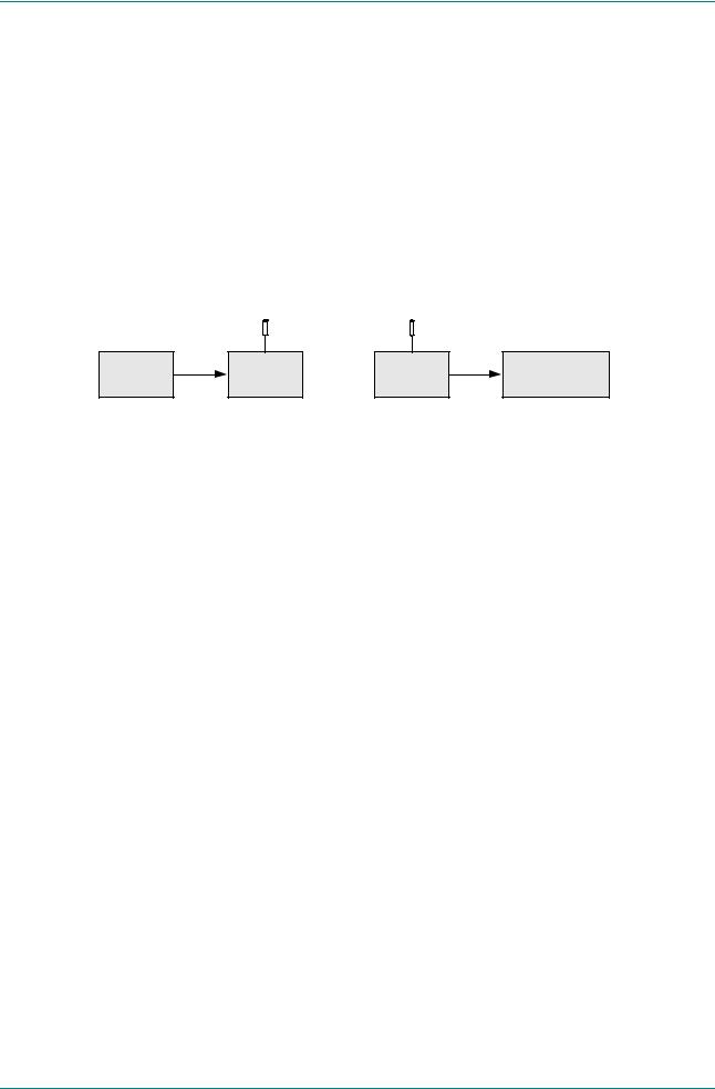
1.2.3DENG Systems
|
70 MHz IF |
|
|
|
E5715/E5750 |
Radio Tx |
Radio Rx |
Rec / Mon |
|
Encoder |
Equipment |
|||
|
|
Figure 1.6: Typical DENG System Configuration
The OFDM modulator fitted in the E5715 and E5750 takes the Encoder’s output transport stream, and uses Coded Orthogonal Frequency Division Multiplexing (COFDM) to spread the data over 1705 carriers (2k mode) or 6817 carriers (8k mode). This means that relatively low data rates can be used on each carrier frequency, and any multipath effects (ghosting) which occur affects only a small amount of data.
The carriers are closely spaced so that their sidebands overlap, but due to the orthogonal relationship between carrier frequencies they do not interfere with each other. This makes the system spectrally efficient.
Noise, multipath effects, co-channel interference and other impairments can cause some bits to be received in error. Therefore, Forward Error Correction (FEC) consisting of Reed-Solomon (RS) coding followed by convolution coding is used to add extra bits to the transmitted signal. This allows a large number of errors at the receive end to be corrected by convolutional (Viterbi) decoding followed by RS decoding.
Five convolutional rates are available: ½, 2/3, ¾, 5/6 and 7/8. These provide different compromises between bit-rate and ruggedness.
The modulation scheme used on each carrier can either be QPSK, 16QAM, or 64QAM. These also provide different compromises between bit-rate and ruggedness, QPSK being the most rugged.
Four guard intervals are available 1/32, 1/16, 1/8, and ¼. These are used to reduce the effects of intersymbol interference at the receive end caused by multipath propagation.
The output of the modulator is 70 MHz IF for connection to a suitable radio transmitter.
Instruction Manual: evolution 5000 E57xx DSNG and DENG Voyager Encoder |
Page 1-7 |
ST.TM.E10076.3 |
|

Introduction to the Basic Encoder
1.3Summary of Features
1.3.1Video Encoding
MPEG-2 Encoding
The Encoder processes a broadcast-standard video signal into a compressed encoded bit-stream in accordance with:
The MPEG-2 Main profile @ Main level (MP@ML) specification (ISO/IEC 13818)
The MPEG-2 4:2:28 profile @ Main Level (422P@ML) specification (ISO/IEC 13818)
Video Encoding Modes
Either the 4:2:0 or 4:2:28 video encoding modes can be selected. The coding mode selected affects the compression techniques, encoder delay and rate control.
Video Inputs
The standard video inputs are:
SDI - Serial Digital Interface - ITU-R BT.656-4, part 3 (D1 serial format) – SMPTE 259 (component only)
Composite Analogue (PAL/NTSC)
Video Input Types
The video input types which are supported are:
625-line composite PAL-B, -D, -G, -H or -I (ITU-R BT. 624-4)
525-line composite NTSC-M (with and without pedestal) or PAL-M (ITU-R BT. 624-4)
Serial digital (ITU-R BT.656-4, part 3) input (D1 serial format) and (ANSI/SMPTE 259M) (component only)
Internal test pattern function
Serial Digital Video Input Error Detection and Handling (EDH)
The serial digital video input supports error detection and handling (EDH)9 as defined by the specification SMPTE RP 165-1994, ‘Error Detection Checkwords and Status Flags for Use in Bit Serial Digital Interfaces for Television’.
Video Encoding Functions
The standard video encoding functions include:
Support for all MP@ML and 422P@ML8 standard coding modes
Selectable bit-rate operation, <1.5 Mbit/s - 50 Mbit/s (see Table 1.3)10
Support for the standard set of video picture resolutions (720, 704, 640, 544, 480, 352) in both 625 and 525 line operation. 352 supports full and half-vertical resolution in both 625 and 525 line operation
84:2:2 is only available when software option M2/ESO2/422 is purchased.
9Error detection and handling is not currently supported.
10Bit-rates lower than 1.5 Mbit/s are only available when the software option M2/ESO2/PU is purchased.
Page 1-8 |
Instruction Manual: evolution 5000 E57xx DSNG and DENG Voyager Encoder |
|
ST.TM.E10076.3 |

Introduction to the Basic Encoder
Fully exhaustive motion estimation
An internal frame synchroniser (see Internal Frame Synchroniser on
Page 1-10)
Support for Active Format Descriptor (AFD) (see Chapter 4, Operating the Equipment Locally, Table 4.36)
Support for a variety of Group of Pictures (GOP) structures with a variable number of B frames
Built-in patented adaptive noise reduction circuitry11
A logo overlay facility whereby the Encoder is able to overlay broadcasters trademarks/logos onto the active video
Motion Estimation
Fully Exhaustive motion estimation is used. It takes a macro block of 16 pixels x 16 pixels and then performs an exhaustive search without subsampling.
Variable Video Bit-rate
The MPEG-2 compression algorithm uses adaptive field/frame coding, forward and backward predictive processing with motion estimation and compensation to reduce the bit-rate to the range shown in Table 1.3.
Table 1.3: Video Bit-rate Range 12
Video Encoding Mode
4:2:0 |
4:2:213 |
1.5 Mbit/s - 15 Mbit/s |
1.5 Mbit/s - 50 Mbit/s |
|
|
NOTE…
Minimum bit-rate is 0.25 Mbit/s when software option M2/ESO2/PU is purchased.
Coding Resolutions
To provide optimum picture quality over the full range of supported bit-rates, the encoded picture resolution is controlled automatically according to the video bit-rate. Alternatively, the user can override this and select manual control, if desired. Coding resolutions are shown in
Table 1.4.
11Noise reduction is only available when software option M2/ESO2/NR is purchased.
12The video bit-rate depends on the Multiplexer bit-rate which is set.
134:2:2 is only available when software option M2/ESO2/422 is purchased.
Instruction Manual: evolution 5000 E57xx DSNG and DENG Voyager Encoder |
Page 1-9 |
ST.TM.E10076.3 |
|

Introduction to the Basic Encoder
Table 1.4: Video Coding Resolutions
625 Line Modes |
525 Line Modes |
|
|
720 pixels x 576 lines |
720 pixels x 480 lines |
|
|
704 pixels x 576 lines |
704 pixels x 480 lines |
|
|
640 pixels x 576 lines |
640 pixels x 480 lines |
|
|
544 pixels x 576 lines |
544 pixels x 480 lines |
|
|
480 pixels x 576 lines |
480 pixels x 480 lines |
|
|
352 pixels x 576 lines |
352 pixels x 480 lines |
|
|
352 pixels x 288 lines |
352 pixels x 240 lines |
|
|
Internal Frame Synchroniser
An internal frame synchroniser is provided to accommodate slight differences between the incoming frame rate and that generated by the stable reference14 used by the Encoder.
Output on Video Loss
The Encoder can be software-configured to show, in the event of video input loss, either:
A test pattern (with or without ident text)
A freeze frame (with or without ident text)
Cut to a black screen (with or without ident text)
1.3.2Audio Encoding
General
Audio can be encoded to:
MPEG-1 Audio (layer 2) standard (sampling rate 32 kHz or 48 kHz).
Dolby Digital (AC-3)15 (sampling rate 32 kHz or 48 kHz)16.
Output bit-rate is selectable in the range 32 kbit/s - 384 kbit/s (dependent on configuration) for MPEG-1 Audio (layer 2) and
56 kbit/s - 640 kbit/s (dependent on configuration) for Dolby Digital (AC-3) coding mode selectable between 1/0 and 2/0.
Dolby Digital (AC-3) pre-encoded audio (IEC 61937 specification) in pass-through mode is also available (it only operates at 48 kHz). This is where an audio stream has already been encoded externally, prior to entering the Encoder.
Linear PCM16 (SMPTE 302M).
Dolby E Pass-through16.
NOTES…
1.See Annex G, Audio Modes for details of setting up the audio.
2.MPEG-1 audio sampling rate is fixed at 48 kHz when controlled from the front panel.
14To ensure broadcast quality it is recommended that the studio reference is fed to HYSNC.
15Dolby Digital (AC-3) is only available when software option M2/ESO2/AC3 is purchased.
16To achieve lip sync in all modes the audio option M2/EOM2/AUDLIN must be used
Page 1-10 |
Instruction Manual: evolution 5000 E57xx DSNG and DENG Voyager Encoder |
|
ST.TM.E10076.3 |

Introduction to the Basic Encoder
Audio Inputs
The standard audio input is:
AUDIO IN – 15-way male D-type - software selectable balanced analogue or digital AES/EBU, with AES/EBU on left only. A break-out cable is supplied which plugs into this connector and provides a more convenient means of connecting the audio inputs via five connectors. There are four XLR female connectors, with the fifth cable being a BNC which provides an AES/EBU 75 digital reference output.
Alternatively, audio can be input embedded as AES/EBU on the serial digital interface (SDI). In this mode a maximum of four stereo pairs can be extracted from any two Data Identifiers (DIDs). Audio may be converted to either of the standard output sampling frequencies,
32 kHz or 48 kHz, by use of the built-in asynchronous sample rate converters. This applies only to audio which is not pre-encoded.
Audio Channels
The Encoder Base Board is capable of processing two stereo pairs, from any of the following17:
SDI Embedded source
Digital source AES/EBU
Analogue source, termination impedance 600 or 20 k
These signals may be processed using the encoding modes in the following section.
MPEG Encoding Modes
The two stereo pairs may be configured in various encoding modes:
Single mono: the left channel is encoded - the signal is output to both XLR connectors at the receiving end. Not available in Linear PCM.
Dual mono: the left and right signals are encoded and carried in the transport stream as a single Packetised Elementary Stream (PES) data stream. The way that the left and right signals are output from the Receiver is dependent on how the routing is set up on the Receiver. Both the left and the right may be output, or the left only, or the right only. This is typically used for multilingual services. Available in MPEG-1 (layer 2) and Linear PCM.
Stereo: A stereo pair is coded as two mono signals - the two signals are output as stereo at the receiving end.
Joint stereo: A stereo pair is coded taking advantage of the stereo nature of the channels - the two signals are output as stereo at the receiving end. Available in MPEG-1 (layer 2) only.
Audio Description Service
Dolby Digital (AC-3) Encoding Modes
1/0: centre
2/0: left and right
17 See Annex G, Audio Modes for details of setting up the audio.
Instruction Manual: evolution 5000 E57xx DSNG and DENG Voyager Encoder |
Page 1-11 |
ST.TM.E10076.3 |
|

Introduction to the Basic Encoder
Test Tones
The equipment can be configured to generate a test tone for alignment purposes. Refer to Annex B, Technical Specification for level and frequency.
Audio Variable Bit-rate
MPEG-1 audio output bit-rate (see Table 1.5) is selectable in the range 32 kbit/s -384 kbit/s (dependent on configuration).
Table 1.5: MPEG-1 Audio Encoding Bit-rates
Bit-rate |
Single |
Dual |
Stereo |
Joint Stereo |
(kbit/s) |
Channel |
Mono |
|
|
|
Mono |
|
|
|
|
|
|
|
|
32 |
|
- |
- |
- |
|
|
|
|
|
48 |
|
- |
- |
- |
|
|
|
|
|
56 |
|
- |
- |
- |
|
|
|
|
|
64 |
|
|
|
|
|
|
|
|
|
80 |
|
- |
- |
- |
|
|
|
|
|
96 |
|
|
|
|
|
|
|
|
|
112 |
|
|
|
|
|
|
|
|
|
128 |
|
|
|
|
|
|
|
|
|
160 |
|
|
|
|
|
|
|
|
|
192 |
|
|
|
|
224 |
- |
|
|
|
|
|
|
|
|
256 |
- |
|
|
|
|
|
|
|
|
320 |
- |
|
|
|
384 |
- |
|
|
|
|
|
|
|
|
Dolby Digital (AC-3)
Dolby Digital (AC-3) audio encoding incorporates digital normalisation, preprocessing (filtering), dynamic range compression and the addition of bit-stream information.
Dolby Pro Logic audio can be carried as stereo audio through the Encoder as long as a suitably high bit-rate is selected.
Page 1-12 |
Instruction Manual: evolution 5000 E57xx DSNG and DENG Voyager Encoder |
|
ST.TM.E10076.3 |
Introduction to the Basic Encoder
Table 1.6: Dolby Digital Audio Encoding Bit-rates
Bit-rate |
Single Channel |
Dual Channel |
(kbit/s) |
Mono (1/0) |
Stereo (2/0) |
|
|
|
56 |
|
- |
64 |
|
- |
|
|
|
80 |
|
- |
|
|
|
96 |
|
|
112 |
|
|
|
|
|
128 |
|
|
|
|
|
160 |
|
|
192 |
|
|
|
|
|
224 |
|
|
|
|
|
256 |
|
|
320 |
|
|
|
|
|
384 |
|
|
|
|
|
448 |
|
|
|
|
|
512 |
|
|
|
|
|
576 |
|
|
|
|
|
640 |
|
|
|
|
|
1.3.3Vertical Blanking Interval (VBI) Line Processing Modes
Introduction
The Encoder has three modes for processing VBI lines.
NOTE…
A maximum of eight VBI lines per field may be extracted. This limit does not apply to Teletext.
VBI in Picture
By selecting the VBI in Picture extended active picture format available in the MPEG 4:2:2 specification the Encoder compresses and transmits the VBI data as part of the active picture. This mode requires up to 3 Mbit/s of extra bit-rate, depending on the amount and complexity of the VBI present.
NOTES…
1.VBI in Picture transmits the VBI waveform as part of the picture and as such will be subject to some distortion. Most analogue VBI types are robust against this type of distortion but others, e.g. video index, are intended for SDI transmission and will not survive MPEG coding/decoding in VBI in Picture mode. VITS test signal and ghost cancellation signal will become corrupted.
2.VBI in Picture is not supported when 3:2 Pulldown is active.
Instruction Manual: evolution 5000 E57xx DSNG and DENG Voyager Encoder |
Page 1-13 |
ST.TM.E10076.3 |
|

Introduction to the Basic Encoder
VBI User Data
Closed Caption data, together with other formats such as VITC and AFD, can be transmitted in the user data field of the video or relevant part of the video stream.
VBI in PID
The Encoder has the ability to extract and transmit a wide variety of VBI line formats. Circuitry on the front end of the equipment incorporates a number of general purpose line grabbers so that known formats of VBI data can be extracted.
The following VBI data formats are supported:
Line 21 (field 1 and field 2) data Services EIA-608 (Closed Caption and V-chip)
Neilson AMOL 1, Neilson AMOL 11
VITC (EBU and SMPTE)
Programme Delivery Control (PDC), via ITU-R system B Teletext extension data packets of type 8/30, format 2 and Line 16 Video Programme System (VPS). Video Programming Teletext (VPT) and VPS are trade names
Wide Screen Signalling (WSS) (line 23) ETS 300 294
Video Index (for Pan Scan, Aspect Ratio and Active Format Descriptor)
The supported VBI line number range is 10-22 and 272-285 for 525 lines and 7-24 and 319-336 for 625 lines
Teletext Extraction
The Encoder supports internal Teletext data extraction (Teletext drop) from the VBI of a video input and formats this data into a transport packet, as specified in the DVB specification EN300-472. The Encoder can extract up to 18 lines of Teletext from each field of the video frame.
Line filters can be invoked to selectively disable any individual lines in this range. The filters are provided to allow the user to ensure that non-Teletext lines (e.g. ITS lines) are not erroneously extracted. The extracted Teletext lines are formatted into PES packets according to the DVB specification. The Teletext PES packets are time-stamped to allow correct alignment of subtitling captions with decoded video.
The following Teletext services are extractable:
Sytem B (WST) Teletext
Video Programming Teletext (VPT), PDC (Packet 8/30 format 2)
Inverted Teletext
1.3.4Data Channels
The basic Encoder supports two data channels, an asynchronous RS-232 and a synchronous RS-442. These are provided as data pipes only, they are not time-stamped.
Page 1-14 |
Instruction Manual: evolution 5000 E57xx DSNG and DENG Voyager Encoder |
|
ST.TM.E10076.3 |

Introduction to the Basic Encoder
1.3.5Outputs
Three ASI-C (copper) outputs supplying a DVB and ATSC18 MPEG-2 transport stream are supplied as standard.
1.3.6IF Modulation
E5714
The internal satellite modulator within the E5714 supports QPSK modulation in accordance with EN 300 421 (DVB-S). It provides a main and monitoring IF Output. The IF frequency can be tuned between 50 MHz and 90 MHz in steps of 125 kHz. The maximum symbol rate is 30 Msym/s 60 MHz to 80 MHz (20 Msym/s at 50 MHz and 90 MHz).
E5740
The satellite modulator fitted within the E5740 is capable of QPSK modulation in accordance with EN 300 421 (DVB-S), and is also capable of 8PSK and 16QAM modulation in accordance with EN 301 210 (DVB-DSNG). It is available with either IF outputs, or L-band outputs.
The IF output frequency can be tuned between 50 MHz and 180 MHz in
1 kHz steps. The L-band output frequency can be tuned between 950 MHz and 1750 MHz in 1 kHz steps. The maximum symbol rate is 48 Msym/s.
E5715/E5750
The OFDM modulator fitted within the E5715 and E5750 provides an IF output at 70 MHz and 0dBm. It is capable of operating in 2k carriers, or 8k carriers transmission modes. It supports FEC rates of ½, 2/3, ¾, 5/6 and 7/8, and guard intervals of 1/32, 1/16, 1/8, and ¼. It can provide QPSK, 16QAM, or 64QAM modulation schemes.
1.3.7Control and Monitoring
Remote control of the Encoder is via the Ethernet network running the Simple Network Management Protocol (SNMP) protocol or via the RS-232/RS-485 remote control port.
Alternatively, Local control is implemented through the front panel keypad and display.
1.3.8Options and Upgrades
Options and Upgrades are described in Chapter 3, Options and Upgrades.
18 ATSC internal PSIP generation is not supported in Build versions 2.1.0 and 2.2.0.
Instruction Manual: evolution 5000 E57xx DSNG and DENG Voyager Encoder Page 1-15 ST.TM.E10076.3

Introduction to the Basic Encoder
1.4Guided Tour
1.4.1Enclosure
There are two sizes of enclosure, 1U and 2U versions. The enclosure is used as a stand-alone unit. All inputs and outputs are via rear panel connectors.
1.4.2The User Interface
The Encoder itself provides no controls at the rear panel but there is a display and keypad at the front panel. All connectors are provided at the rear panel. Control and monitoring may be performed in a variety of ways (see Section 1.3.7, Control and Monitoring). Once configured, the system runs without the need for further intervention unless system configuration requirements change.
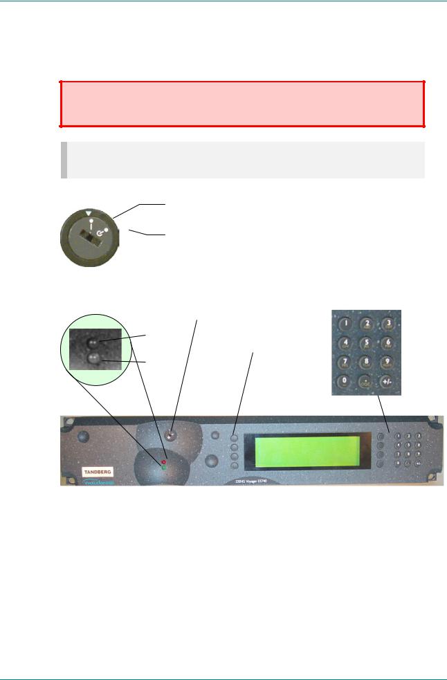
1.4.3Front Panel Description
Front Panel Display, Navigation Keys, Softkeys, Keyboard
The 1U Encoder provides navigation keys to access and input data. The 2U Encoder provides a keypad and softkeys to access and input data. There are two LED indicators, located on the left of the front panel (see
Figure 1.7 and Figure 1.9).
The front panel display and navigation keys/softkeys/keyboard are used as a local control method to set up and configure the Encoder (see Chapter 4, Operating the Equipment Locally). They can also be used as quick method for accessing the status of the equipment.
Table 1.7: Front Panel Indicators
Indicator |
Colour |
Description |
|
|
|
Alarm |
Red |
This LED is lit when an alarm condition has been detected by the Encoder. |
|
|
|
Power |
Green |
This LED is lit when power is being received by the Encoder. |
|
|
|
Alarm
|
Enter |
Power |
Cancel |
|
Navigation keys, to select options
Figure 1.7: 1U Encoder Front Panel Indicators
Page 1-16 |
Instruction Manual: evolution 5000 E57xx DSNG and DENG Voyager Encoder |
|
ST.TM.E10076.3 |
Introduction to the Basic Encoder
Power Supply Stand-by Switch
The use of this switch puts the Encoder into stand-by mode. It powers down the supply rails of the display and internal circuits within the unit. The switch type avoids accidental powering-down of the Encoder. For normal use ensure that the I is always at the top (see Figure 1.8).
WARNING…
THIS IS NOT A MAINS SWITCH AND DOES NOT ISOLATE THE ENCODER FROM THE POWER
SUPPLY.
NOTE…
Earlier versions of the 1U Encoder may not have this switch fitted.
On position
Stand-by position
Figure 1.8: Stand-by Switch
Power Supply
Stand-by Switch
Alarm |
|
|
Softkeys, to |
Power |
select options |
|
Figure 1.9: 2U Encoder Front Panel Indicators
1.4.4Rear Panel Description
Introduction
The Encoder provides connectors at the rear panel. All, except the power connector, are physically located on the separate modules which comprise the Encoder.
Instruction Manual: evolution 5000 E57xx DSNG and DENG Voyager Encoder |
Page 1-17 |
ST.TM.E10076.3 |
|

Introduction to the Basic Encoder
1U Chassis
IF Out Main |
IF Out Monitor |
Option Slot 2
Base Board
Alarm |
RS-422 |
RS-232 |
RS-232/ Ethernet ASI Outputs SDI In H Sync |
Composite |
Audio In and |
|
Data |
Data |
RS-485 |
Video |
Audio |
|
|
|
Control |
|
Reference Out |
Figure 1.10: E5714 (1U) Rear Panel Component Parts and Connectors |
|
|
|||
|
IF Out 1 |
IF Out 2 |
|
|
|
Option Slot 2
Base Board
Alarm |
RS-422 |
RS-232 |
RS-232/ |
Ethernet ASI Outputs SDI In H Sync Composite |
Audio In and |
|
Data |
Data |
RS-485 |
Video |
Audio |
|
|
|
Control |
|
Reference Out |
Figure 1.11: E5715 (1U) Rear Panel Component Parts and Connectors
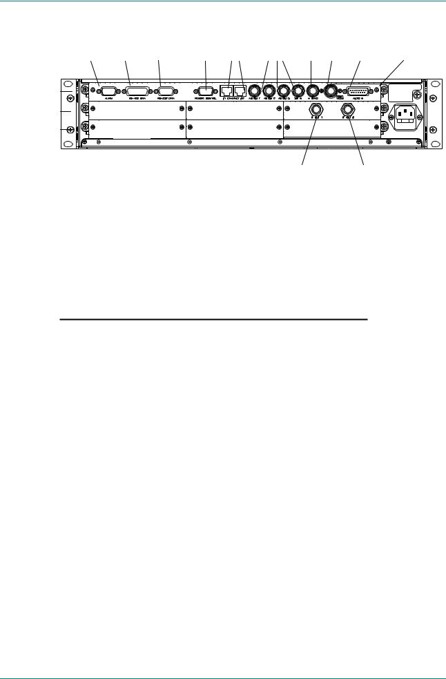
2U Chassis
|
RS-422 RS-232 |
RS-232/ |
|
ASI |
|
Audio In and |
|
|
RS-485 |
|
Composite |
Audio |
|||
Alarm |
Data |
Data |
Control |
Ethernet |
Outputs |
SDI In H Sync Video |
Reference Out |
Base Board 
Option Slots 4-6  Option Slot 4 Option Slot 5 Option Slot 6
Option Slot 1 |
Option Slot 1 |
|
IF Out Main IF Out Monitor |
TANDBERG Television |
|
use only |
Figure 1.12: E5740 (2U) Rear Panel Component Parts and Connectors
Page 1-18 |
Instruction Manual: evolution 5000 E57xx DSNG and DENG Voyager Encoder |
|
ST.TM.E10076.3 |
Introduction to the Basic Encoder
|
RS-422 |
|
RS-232/ |
|
ASI |
|
|
Audio In and |
|
RS-232 |
RS-485 |
|
|
Composite |
Audio |
||
Alarm |
Data |
Data |
Control |
Ethernet |
Outputs |
SDI In |
H Sync Video |
Reference Out |
Base Board |
|
|
|
|
|
|
|
|
Option Slots 4-5 |
Option Slot 4 |
|
Option Slot 5 |
|
|
|
|
|
Option Slot 1-3 |
Option Slot 1 |
|
Option Slot 2 |
|
Option Slot 3 |
|
||
|
|
|
|
|
|
|
||
|
|
|
|
|
|
IF OUT 1 |
IF OUT 2 |
|
Figure 1.13: E5750 (2U) Rear Panel Component Parts and Connectors
1.4.5Boards in the Basic Encoder
The basic Encoder contains two boards mounted horizontally in the enclosure (see Table 1.8). Option modules can be fitted in the remaining slots (see Equipment Models on page 1-3 and Chapter 3, Options and Upgrades).
Table 1.8: Boards in the Basic Encoder
Model Number |
Card |
|
|
|
|
E5714 |
S11171 Encoder Base Board |
|
|
|
|
|
S12376 Tuneable QPSK Modulator |
|
|
|
|
E5715 |
S11171 Encoder Base Board |
|
|
|
|
|
S12524 OFDM Modulator |
|
|
|
|
E5740-IF |
S11171 |
Encoder Base Board |
|
|
|
|
S10872 |
70/140 MHz Satellite Modulator |
|
|
|
E5740-LBAND |
S11171 Encoder Base Board |
|
|
|
|
|
S12695 |
L-Band Satellite Modulator |
|
|
|
E5750 |
S11171 Encoder Base Board |
|
|
|
|
|
S12524 OFDM Modulator |
|
|
|
|
Access to the modules or boards in the basic Encoder is not required for normal operation and may invalidate the warranty.
Instruction Manual: evolution 5000 E57xx DSNG and DENG Voyager Encoder |
Page 1-19 |
ST.TM.E10076.3 |
|

Introduction to the Basic Encoder
BLANK
Page 1-20 |
Instruction Manual: evolution 5000 E57xx DSNG and DENG Voyager Encoder |
|
ST.TM.E10076.3 |

Chapter 2
Installing the Equipment
Contents
2.1 |
Introduction ............................................................... |
2-3 |
|
|
2.1.1 |
Read This First! ............................................ |
2-3 |
|
2.1.2 |
General......................................................... |
2-3 |
|
2.1.3 |
Site Requirements ........................................ |
2-3 |
|
|
Power Supplies............................................. |
2-3 |
|
|
Environment.................................................. |
2-3 |
|
|
Lightning Protection...................................... |
2-3 |
|
2.1.4 |
EMC Compliance Statements....................... |
2-3 |
|
|
EN 55022 / AS/NZS 3548............................. |
2-3 |
|
|
FCC .............................................................. |
2-4 |
2.2 |
Preliminary Checks ................................................... |
2-4 |
|
|
2.2.1 |
Mechanical Inspection .................................. |
2-4 |
|
2.2.2 Moving the Equipment Safely ....................... |
2-4 |
|
2.3 |
Installing the Equipment............................................ |
2-4 |
|
|
2.3.1 |
Fixing Method ............................................... |
2-4 |
|
2.3.2 |
Cable Routing............................................... |
2-5 |
|
2.3.3 |
Equipment Access ........................................ |
2-5 |
|
2.3.4 |
Ventilation..................................................... |
2-5 |
2.4 AC Mains Operating Voltage and Earthing ............... |
2-7 |
||
|
2.4.1 |
AC Power Supply.......................................... |
2-7 |
|
2.4.2 Power Cable and Earthing............................ |
2-7 |
|
|
|
General......................................................... |
2-7 |
|
|
Protective Earth/Technical Earth .................. |
2-7 |
|
|
Connecting the Encoder to the AC Power |
|
|
|
Supply........................................................... |
2-8 |
2.5 DC Operating Voltage and Earthing.......................... |
2-8 |
||
|
2.5.1 |
DC Power Supply ......................................... |
2-8 |
|
2.5.2 DC Power Cable and Earthing...................... |
2-9 |
|
|
|
General......................................................... |
2-9 |
|
|
DC Power Connector (Encoder) ................. |
2-10 |
2.6 Signal Connections For the Basic Unit .................... |
2-10 |
|
2.6.1 |
Introduction ................................................. |
2-10 |
2.6.2 |
Connecting Up the Basic Encoder .............. |
2-12 |
2.6.3 |
Power Supply .............................................. |
2-13 |
2.6.4 |
Technical Earth ........................................... |
2-13 |
2.6.5 |
Video Inputs ................................................ |
2-13 |
|
SDI IN.......................................................... |
2-13 |
|
H SYNC....................................................... |
2-13 |
|
COMP VIDEO ............................................. |
2-14 |
2.6.6 |
Audio Inputs ................................................ |
2-14 |
2.6.7 |
ASI OUT 1, 2 and 3 Outputs ....................... |
2-15 |
2.6.8 |
Control Interfaces........................................ |
2-15 |
|
Connection.................................................. |
2-15 |
|
Ethernet #1 and #2...................................... |
2-16 |
|
Alarm........................................................... |
2-16 |
|
Remote Control........................................... |
2-17 |
2.6.9 |
Data............................................................. |
2-17 |
|
RS-232 Connector ...................................... |
2-17 |
|
RS-422 Connector ...................................... |
2-18 |
2.6.10 |
Satellite Modulator IF Output (E5714 and |
|
|
E5740 IF) .................................................... |
2-19 |
|
IF Out (Main)............................................... |
2-19 |
|
IF Out (Monitor)........................................... |
2-19 |
2.6.11 |
Satellite Modulator L-Band Output (E5740 |
|
|
LBAND) ....................................................... |
2-19 |
|
L-Band In..................................................... |
2-19 |
|
L-Band Out (Main)....................................... |
2-20 |
|
L-Band Out (Monitor) .................................. |
2-20 |
|
Up-Converter Power ................................... |
2-20 |
2.6.12 |
OFDM Modulator Outputs (E5715 and |
|
|
E5750)......................................................... |
2-20 |
|
IF Out 1 ....................................................... |
2-20 |
Instruction Manual: evolution 5000 E57xx DSNG and DENG Voyager Encoder |
Page 2-1 |
ST.TM.E10076.3 |
|

Installing the Equipment
|
IF Out 2 ...................................................... |
2-21 |
2.7 Powering Up/Down.................................................. |
2-21 |
|
2.7.1 |
Before Powering Up .................................... |
2-21 |
2.7.2 |
Powering Up................................................ |
2-21 |
2.7.3 |
Powering Down ........................................... |
2-21 |
2.8 Setting the Encoder IP Address .............................. |
2-22 |
|
2.8.1 Methods of Changing the Encoder IP |
|
|
|
Address....................................................... |
2-22 |
2.8.2 From the Front Panel Menus ...................... |
2-22 |
|
2.8.3 |
Via Telnet.................................................... |
2-22 |
List of Figures |
|
|
Figure 2.1: Fitting the Encoder into a Rack .................................... |
2-5 |
|
Figure 2.2: Air Path Through the Enclosure ................................... |
2-6 |
|
Figure 2.3: E5714 (1U) Rear Panel Component Parts and |
|
|
Connectors.................................................................. |
2-10 |
|
Figure 2.4: E5715 (1U) Rear Panel Component Parts and |
|
|
Connectors.................................................................. |
2-11 |
|
Figure 2.5: E5740-IF (2U) Rear Panel Component Parts and |
|
|
Connectors.................................................................. |
2-11 |
|
Figure 2.6: E5740-L-Band (2U) Rear Panel Component Parts |
|
|
and Connectors........................................................... |
2-11 |
|
Figure 2.7: E5750 (2U) Rear Panel Component Parts and |
|
|
Connectors.................................................................. |
2-12 |
|
Figure 2.8: Equipment Connections for the Basic Unit................. |
2-12 |
|
Figure 2.9: Main Telnet Menu....................................................... |
2-22 |
|
List of Tables
Table 2.1: Supply Cable Wiring Colours........................................ |
2-7 |
Table 2.2: DC Input Connector and Cable details ....................... |
2-10 |
Table 2.3: SDI Connector ............................................................ |
2-13 |
Table 2.4: H SYNC Connector .................................................... |
2-14 |
Table 2.5: COMP VIDEO Connector ........................................... |
2-14 |
Table 2.6: Audio In Connector..................................................... |
2-15 |
Table 2.7: ASI OUT 1, 2 and 3 Connectors................................. |
2-15 |
Table 2.8: Ethernet Connector .................................................... |
2-16 |
Table 2.9: Alarm Connector......................................................... |
2-16 |
Table 2.10: Remote Control Connector (RS-232/ RS-485) ......... |
2-17 |
Table 2.11: RS-232 Data Connector (Base Board) - |
|
Asynchronous ............................................................ |
2-17 |
Table 2.12: RS-422 Data Connector (Base Board) - |
|
Synchronous .............................................................. |
2-18 |
Table 2.13: IF Out Connector (Main)........................................... |
2-19 |
Table 2.14: IF Output Connector (Monitor).................................. |
2-19 |
Table 2.15: L-band In Connector................................................. |
2-19 |
Table 2.16: L-band Out (Main) Connector................................... |
2-20 |
Table 2.17: IF Out 1 Connector ................................................... |
2-20 |
Table 2.18: IF Out 2 Connector ................................................... |
2-21 |
Page 2-2 |
Instruction Manual: evolution 5000 E57xx DSNG and DENG Voyager Encoder |
|
ST.TM.E10076.3 |
 Loading...