


X4200
Table of contents
 Loading...
Sun Fire
X4100/X4100 M2
and X4200/X4200 M2
Servers Installation Guide
™
Sun Microsystems, Inc.
www.sun.com
Part No. 819-1155-16
May 2007, Revision A
Submit comments about this document at: http://www.sun.com/hwdocs/feedback

Copyright 2007 Sun Microsystems, Inc., 4150 Network Circle, Santa Clara, California 95054, U.S.A. All rights reserved.
Sun Microsystems, Inc. has intellectual property rights relating to technology that is described in this document. In particular, and without
limitation, these intellectual property rights may include one or more of the U.S. patents listed at http://www.sun.com/patents and one or
more additional patents or pending patent applications in the U.S. and in other countries.
This document and the product to which it pertains are distributed under licenses restricting their use, copying, distribution, and
decompilation. No part of the product or of this document may be reproduced in any form by any means without prior written authorization of
Sun and its licensors, if any.
Third-party software, including font technology, is copyrighted and licensed from Sun suppliers.
Parts of the product may be derived from Berkeley BSD systems, licensed from the University of California. UNIX is a registered trademar k in
the U.S. and in other countries, exclusively licensed through X/Open Company, Ltd.
Sun, Sun Microsystems, the Sun logo, Java, AnswerBook2, docs.sun.com, Sun Fire,Sun Netra, and Solaris are trademarks or registered
trademarks of Sun Microsystems, Inc. in the U.S. and in other countries.
All SPARC trademarks are used under license and are trademarks or registered trademarks of SPARC International, Inc. in the U.S. and in other
countries. Products bearing SPARC trademarks are based upon an architecture developed by Sun Microsystems, Inc.
The OPEN LOOK and Sun™ Graphical User Interface was developed by Sun Microsystems, Inc. for its users and licensees. Sun acknowledges
the pioneering efforts of Xerox in researching and developing the concept of visual or graphical user interfaces for the computer industry. Sun
holds a non-exclusive license from Xerox to the Xerox Graphical User Interface, which license also covers Sun’s licensees who implement OPEN
LOOK GUIs and otherwise comply with Sun’s written license agreements.
U.S. Government Rights—Commercial use. Government users are subject to the Sun Microsystems, Inc. standard license agreement and
applicable provisions of the FAR and its supplements.
DOCUMENTATION IS PROVIDED "AS IS" AND ALL EXPRESS OR IMPLIED CONDITIONS, REPRESENTATIONS AND WARRANTIES,
INCLUDING ANY IMPLIED WARRANTY OF MERCHANTABILITY, FITNESS FOR A PARTICULAR PURPOSE OR NON-INFRINGEMENT,
ARE DISCLAIMED, EXCEPT TO THE EXTENT THAT SUCH DISCLAIMERS ARE HELD TO BE LEGALLY INVALID.
Copyright 2007 Sun Microsystems, Inc., 4150 Network Circle, Santa Clara, Californie 95054, Etats-Unis. Tous droits réservés.
Sun Microsystems, Inc. a les droits de propriété intellectuels relatants à la technologie qui est décrit dans ce document. En particulier, et sans la
limitation, ces droits de propriété intellectuels peuvent inclure un ou plus des brevets américains énumérés à http://www.sun.com/patents et
un ou les brevets plus supplémentaires ou les applications de brevet en attente dans les Etats-Unis et dans les autres pays.
Ce produit ou document est protégé par un copyright et distribué avec des licences qui en restreignent l’utilisation, la copie, la distribution, et la
décompilation. Aucune partie de ce produit ou document ne peut être reproduite sous aucune forme, par quelque moyen que ce soit, sans
l’autorisation préalable et écrite de Sun et de ses bailleurs de licence, s’il y en a.
Le logiciel détenu par des tiers, et qui comprend la technologie relative aux polices de caractères, est protégé par un copyright et licencié par des
fournisseurs de Sun.
Des parties de ce produit pourront être dérivées des systèmes Berkeley BSD licenciés par l’Université de Californie. UNIX est une marque
déposée aux Etats-Unis et dans d’autres pays et licenciée exclusivement par X/Open Company, Ltd.
Sun, Sun Microsystems, le logo Sun, Java, AnswerBook2, docs.sun.com, Sun Fire, Sun Netra, et Solaris sont des marques de fabrique ou des
marques déposées de Sun Microsystems, Inc. aux Etats-Unis et dans d’autres pays.
Toutes les marques SPARC sont utilisées sous licence et sont des marques de fabrique ou des marques déposées de SPARC International, Inc.
aux Etats-Unis et dans d’autres pays. Les produits portant les marques SPARC sont basés sur une architecture développée par Sun
Microsystems, Inc.
L’interface d’utilisation graphique OPEN LOOK et Sun™ a été développée par Sun Microsystems, Inc. pour ses utilisateurs et licenciés. Sun
reconnaît les efforts de pionniers de Xerox pour la recherche et le développement du concept des interfaces d’utilisation visuelle ou graphique
pour l’industrie de l’informatique. Sun détient une license non exclusive de Xerox sur l’interface d’utilisation graphique Xerox, cette licence
couvrant également les licenciées de Sun qui mettent en place l’interface d ’utilisation graphique OPEN LOOK et qui en outre se conforment aux
licences écrites de Sun.
LA DOCUMENTATION EST FOURNIE "EN L’ÉTAT" ET TOUTES AUTRES CONDITIONS, DECLARATIONS ET GARANTIES EXPRESSES
OU TACITES SONT FORMELLEMENT EXCLUES, DANS LA MESURE AUTORISEE PAR LA LOI APPLICABLE, Y COMPRIS NOTAMMENT
TOUTE GARANTIE IMPLICITE RELATIVE A LA QUALITE MARCHANDE, A L’APTITUDE A UNE UTILISATION PARTICULIERE OU A
L’ABSENCE DE CONTREFAÇON.

Contents
Preface v
1. Setting Up the Server Hardware 1
Installation Overview 1
Installing the Server Into a Rack With Optional Slide Rails 2
Disassembling the Slide Rails Before Installation 3
Installing the Mounting Brackets Onto the Server 4
Attaching the Slide-Rail Assemblies to the Rack 5
Installing the Server Into the Slide Rail Assemblies 6
Installing the Cable Management Assembly 7
Attaching and Routing Cables 11
Verifying Operation of the Slide Rails and CMA 12
Cabling 13
Powering On and Off the Server 16
Applying Standby Power for Initial Service Processor Configuration 16
Powering On Main Power Mode 17
Shutting Down Main Power Mode 17
iii

2. Setting Up the Server Software 19
Introduction to the Integrated Lights Out Manager 19
Connecting to the ILOM Service Processor 21
Connecting to ILOM Using a Serial Connection 21
Connecting to ILOM Using an Ethernet Connection 23
Setting Up Platform Operating System and Driver Software 29
3. Configuring the Preinstalled Solaris 10 Operating System 31
Before You Begin 31
Installation Worksheet 32
Selecting Your Console Output 35
Configuring the Preinstalled Solaris 10 Operating System 36
Solaris 10 User Documentation 39
Downloading Solaris 10 OS Software 39
Solaris 10 OS Training 39
Index 41
iv Sun Fire X4100/X4100 M2 and X4200/X4200 M2 Servers Installation Guide • May 2007
Preface
This Installation Guide contains procedures for installing the server in a rack, cabling,
and powering on the server. It also contains procedures for connecting to the service
processor administrator account. Links to documentation for configuring the
preinstalled Solaris 10 software or for installing other supported operating systems
are also included.
Related Documentation
For a description of the document set, see the Where To Find Documentation sheet that
is packed with your system and available at the product's documentation site. Refer
to the following URL, then navigate to your product:
http://www.sun.com/products-nsolutions/hardware/docs/Servers/x64_servers/index.html
This site also contains translated versions of some of these documents in French,
Simplified Chinese, Traditional Chinese, Korean, and Japanese. English
documentation is revised more frequently and might be more up-to-date than the
translated documentation.
For all Sun documentation, refer to:
http://www.sun.com/documentation
For Solaris and other software documentation, refer to:
http://docs.sun.com
v
Product Updates
For product updates that you can download for the Sun Fire X4100 or X4200 servers,
please visit the following Web site:
http://www.sun.com/servers/entry/x4100/downloads.jsp
This site contains updates for firmware and drivers, as well as CD-ROM .iso
images.
Using UNIX Commands
This document might not contain information about basic UNIX® commands and
procedures such as shutting down the system, booting the system, and configuring
devices. Refer to the following for this information:
■ Software documentation that you received with your system
■ Solaris™ Operating System documentation, which is at:
http://docs.sun.com
Third-Party Web Sites
Sun is not responsible for the availability of third-party web sites mentioned in this
document. Sun does not endorse and is not responsible or liable for any content,
advertising, products, or other materials that are available on or through such sites
or resources. Sun will not be responsible or liable for any actual or alleged damage
or loss caused by or in connection with the use of or reliance on any such content,
goods, or services that are available on or through such sites or resources.
vi Sun Fire X4100/X4100 M2 and X4200/X4200 M2 Servers Installation Guide • May 2007
Typographic Conventions
Typeface
AaBbCc123 The names of commands, files,
AaBbCc123 What you type, when contrasted
AaBbCc123 Book titles, new words or terms,
* The settings on your browser might differ from these settings.
*
Meaning Examples
Edit your.login file.
and directories; on-screen
computer output
with on-screen computer output
words to be emphasized.
Replace command-line variables
with real names or values.
Use ls -a to list all files.
% You have mail.
%
su
Password:
These are called class options.
You must be superuser to do this.
To delete a fil e , type rm filename.
Sun Welcomes Your Comments
Sun is interested in improving its documentation and welcomes your comments and
suggestions. You can submit your comments by going to:
http://www.sun.com/hwdocs/feedback
Please include the title and part number of your document with your feedback:
Sun Fire X4100/X4100 M2 and X4200/X4200 M2 Servers Installation Guide, part number
819-1155-16
Preface vii

viii Sun Fire X4100/X4100 M2 and X4200/X4200 M2 Servers Installation Guide • May 2007
CHAPTER
1
Setting Up the Server Hardware
This chapter contains the following topics:
■ “Installation Overview” on page 1
■ “Installing the Server Into a Rack With Optional Slide Rails” on page 2
■ “Cabling” on page 13
■ “Powering On and Off the Server” on page 16
Note – The information in this book applies to all Sun Fire™ X4100/X4100 M2 and
X4200/X4200 M2 servers, unless otherwise noted.
Installation Overview
After unpacking your server, perform the following tasks, which are described in the
documentation as indicated:
1. If desired, install the server into a rack using orderable slide-rails. See “Installing
the Server Into a Rack With Optional Slide Rails” on page 2.
2. Connect all cables, peripherals, and power cords. See “Cabling” on page 13 for an
illustration of the server’s back panel connector ports.
3. Power on and boot the server as described in “Powering On and Off the Server”
on page 16.
4. Connect to the service processor as described in Chapter 2.
1
5. Configure the preinstalled Solaris™ operating system or install a supported
operating system of your choice. For details, refer to one of the following:
■ “Configuring the Preinstalled Solaris 10 Operating System” on page 36
■ Sun Fire X4100/X4100 M2 and X4200/X4200 M2 Servers Operating System
Installation Guide, 819-1158
■ Sun Fire X4100/X4100 M2 and X4200/X4200 M2 Servers Windows Operating
System Installation Guide, 819-4346
6. Customize your server as needed. For details, refer to the “System Management”
section of the online information system or the Integrated Lights-Out Manager
Administration Guide, 820-0280-10.
Installing the Server Into a Rack With Optional Slide Rails
To install your server in a four-post rack using the orderable slide-rail option, follow
these procedures. These slide-rails are compatible with a wide range of equipment
racks that meet the following standards:
■ Four-post structure (mounting at both front and rear). Two-post racks are not
compatible.
■ Rack horizontal opening and unit vertical pitch conforming to ANSI/EIA
310-D-1992 or IEC 60927 standards.
■ Distance between front and rear mounting planes between 610 mm and 915 mm
(24 inches to 36 inches).
■ Clearance depth (to front cabinet door) in front of front rack mounting plane at
least 25.4 mm (1 inch).
■ Clearance depth (to rear cabinet door) behind front rack mounting plane at least
800 mm (31.5 inches) or 700 mm (27.5 inches) without cable management arm.
■ Clearance width (between structural supports and cable troughs) between front
and rear mounting planes at least 456 mm (18 inches).
Note – Although the Sun Fire X4100/X4100 M2 server is pictured in the illustrations
in this section, these procedures also apply to the Sun Fire X4200/X4200 M2 server.
Caution – Always load equipment into a rack from the bottom up so that it will not
become top-heavy and tip over. Deploy your rack’s anti-tilt bar to prevent the rack
from tipping during equipment installation.
2 Sun Fire X4100/X4100 M2 and X4200/X4200 M2 Servers Installation Guide • May 2007
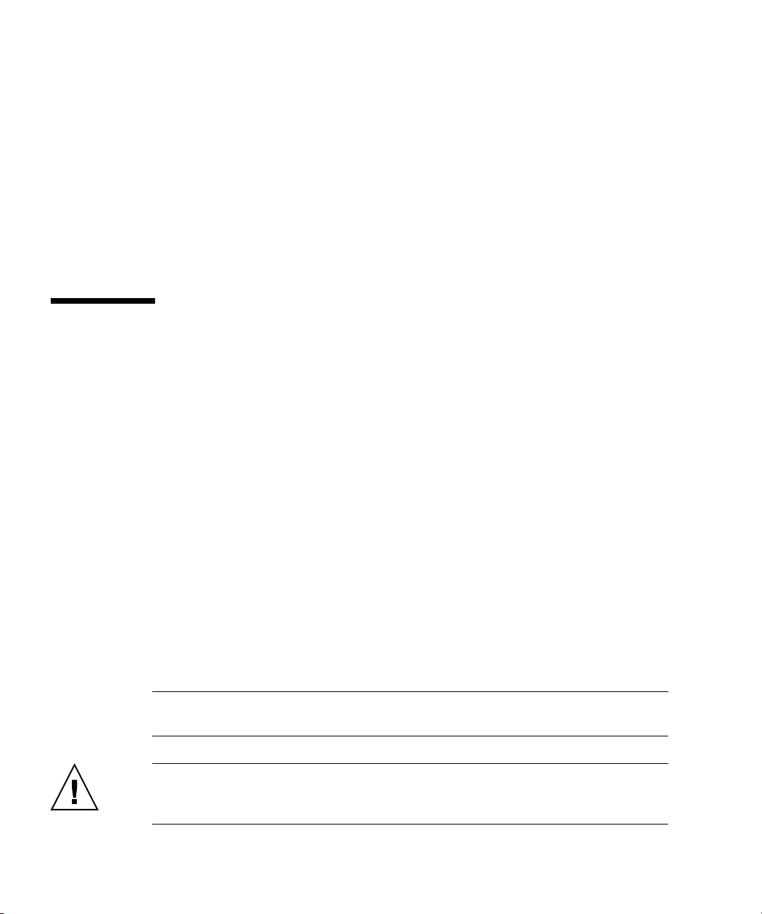
Disassembling the Slide Rails Before Installation
Use this procedure to remove the mounting brackets from the slide-rail assemblies.
1. Unpack the slide-rails.
2. Locate the slide-rail lock at the front of one of the slide-rail assemblies, as shown
FIGURE 1-1.
in
3. Squeeze and hold the tabs at the top and bottom of the lock while you pull the
mounting bracket out of the slide-rail assembly, until it reaches the stop. See
FIGURE 1-1.
4. Pull the mounting bracket release button toward the front of the mounting
bracket, as shown in
bracket from the slide-rail assembly.
5. Repeat the procedure for the remaining slide rail assembly.
Mounting bracket
release button
FIGURE 1-1, and simultaneously withdraw the mounting
FIGURE 1-1 Disassembling the Slide-Rail Before Installation
Slide-rail lock
Chapter 1 Setting Up the Server Hardware 3
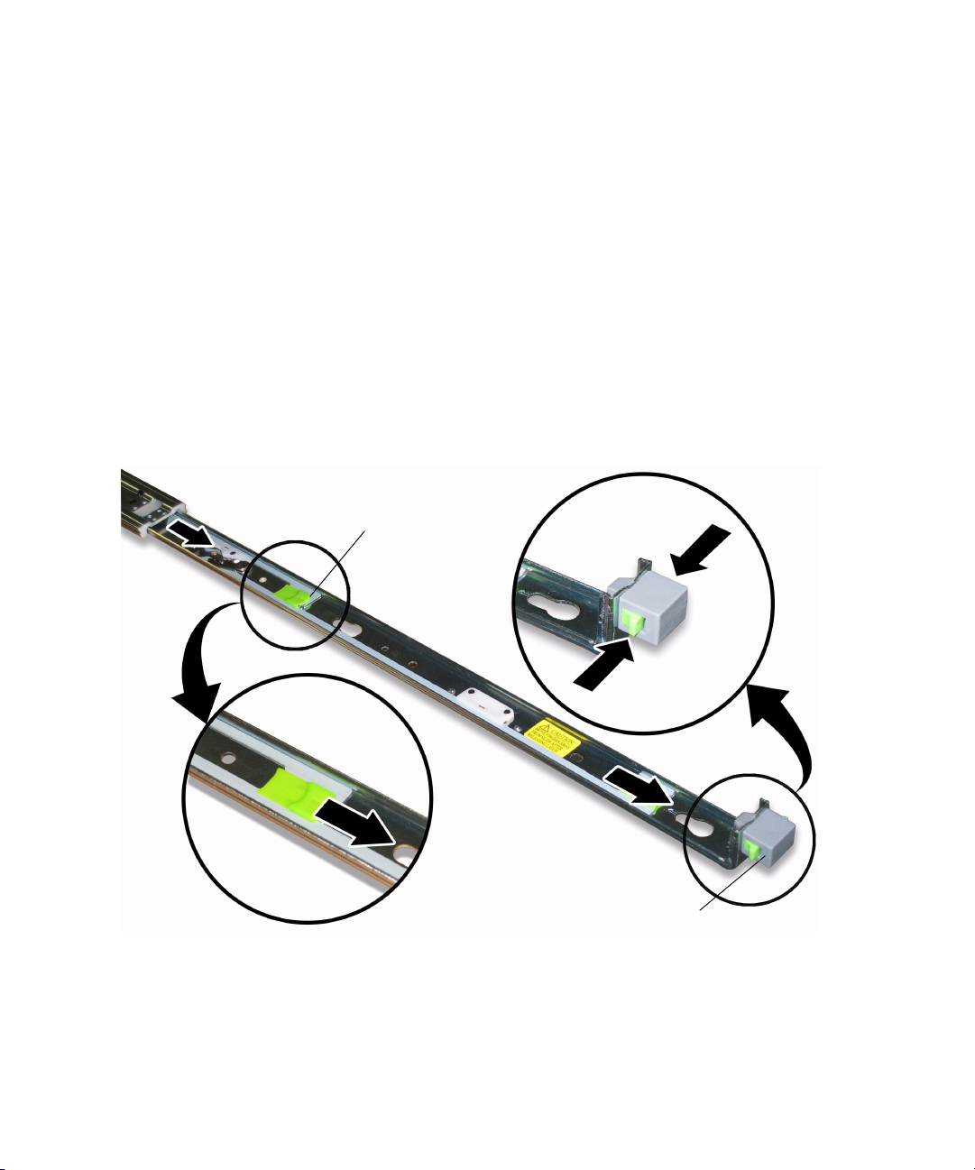
Installing the Mounting Brackets Onto the Server
Use this procedure to install the mounting brackets onto the sides of the server.
1. Position a mounting bracket against the chassis so that the slide-rail lock is at the
server front, and the three keyed openings on the mounting bracket are aligned
with the three locating pins on the side of the chassis. See
FIGURE 1-2.
Chassis front
Slide-rail lock
FIGURE 1-2 Aligning the Mounting Bracket With the Server Chassis
Mounting bracket
2. With the heads of the three chassis locating pins protruding though the three
keyed openings in the mounting bracket, pull the mounting bracket toward the
front of the chassis until the mounting-bracket clip locks into place with an
audible click. See
FIGURE 1-2.
3. Verify that all three locating pins are trapped in the keyed openings and that the
rear locating pin has engaged the mounting-bracket clip. See
4. Repeat the procedure to install the remaining mounting bracket on the other side
of the server.
4 Sun Fire X4100/X4100 M2 and X4200/X4200 M2 Servers Installation Guide • May 2007
Mounting-bracket clip
FIGURE 1-2.
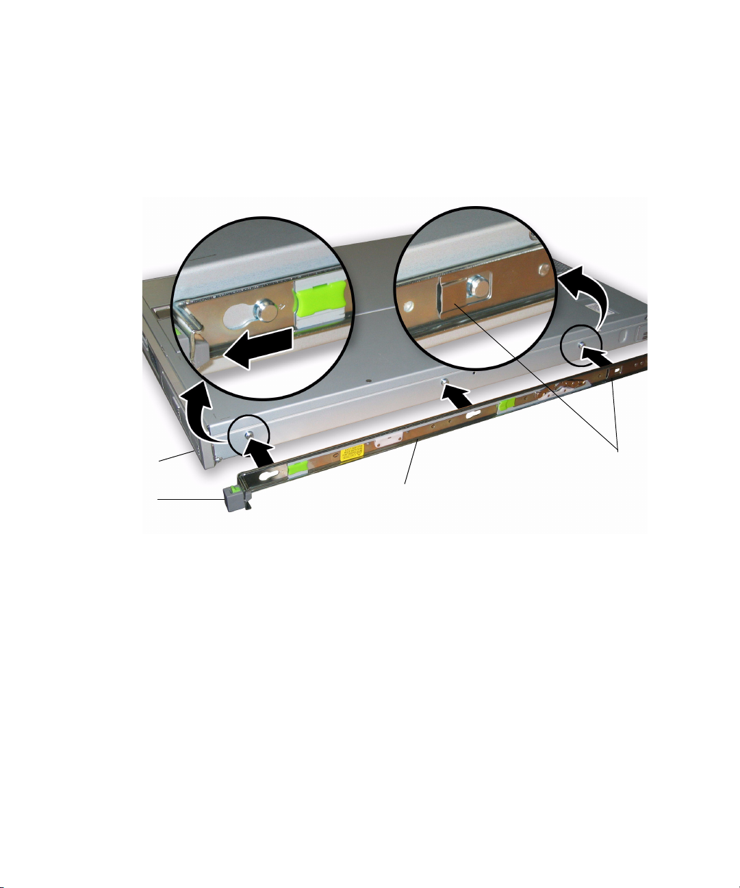
1. Position a slide-rail assembly in your rack so that the brackets at each end of the
2. Attach the slide-rail assembly to the rack posts.
Slide-rail
assembly
with mounting
bracket removed
Attaching the Slide-Rail Assemblies to the Rack
Use this procedure to install the slide-rail assemblies to the rack.
slide-rail assembly are on the outside of the front and rear rack posts. See
FIGURE 1-3.
The method used to attach the slide-rails varies depending on the type of rack:
■ If your rack has threaded mounting holes in the rack posts, first determine
whether the threads are metric or standard, then insert the correct mounting
screws through the slide-rail brackets and into the threaded holes.
■ If your rack does not have threaded mounting holes, insert the mounting screws
through both the slide-rail brackets and rack posts, then secure them with the
caged nuts.
Rack post
Slide-rail assembly
bracket on outside
of rack post
FIGURE 1-3 Slide-Rail Assembly Mounting to Rack Post
3. Repeat the procedure for the remaining slide rail assembly.
Chapter 1 Setting Up the Server Hardware 5
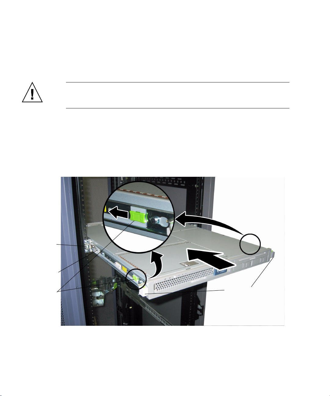
Installing the Server Into the Slide Rail Assemblies
Use this procedure to install the server chassis, with mounting brackets, into the
slide-rail assemblies that are mounted to the rack.
Caution – This procedure requires a minimum of two people because of the weight
of the server. Attempting this procedure alone could result in equipment damage or
personal injury.
1. Push the slide-rails into the slide-rail assemblies as far as possible.
2. Raise the server so that the rear ends of the mounting brackets are aligned with
the slide-rail assemblies that are mounted in the equipment rack. See
3. Insert the mounting brackets into the slide-rails, then push the server into the
rack until the mounting brackets encounter the slide-rail stops (approximately 12
inches or 30 cm).
FIGURE 1-4.
Slide-rail
assembly
mounted on
rack post
Mounting bracket
inserted into
slide-rail
Slide-rail
release button
FIGURE 1-4 Inserting the Server With Mounting Brackets Into the Slide-Rails
6 Sun Fire X4100/X4100 M2 and X4200/X4200 M2 Servers Installation Guide • May 2007
Slide-rail locks
4. Simultaneously pull and hold the slide rail release buttons on each mounting
bracket while you push the server into the rack. See
FIGURE 1-4.
Continue pushing until the slide-rail locks on the front of the mounting brackets
engage the slide-rail assemblies.
Caution – Verify that the server is securely mounted in the rack and that the slide-
rails locks are engaged with the mounting brackets before continuing.
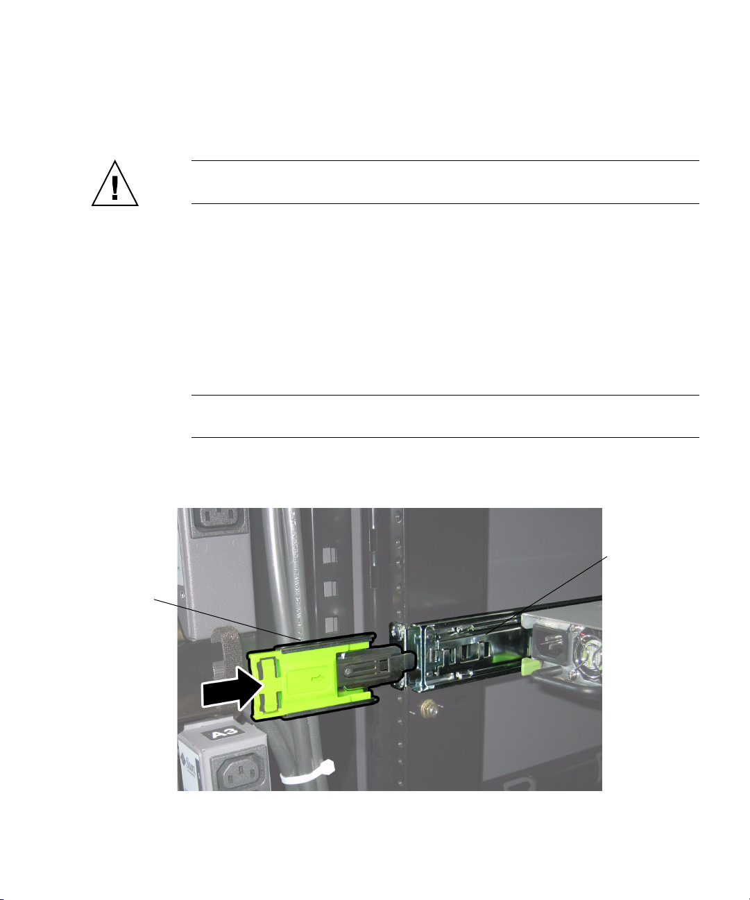
Installing the Cable Management Assembly
Use this procedure to install an optional cable management assembly (CMA).
1. Unpack the CMA parts.
2. Take the CMA to the rear of the equipment rack and ensure that you have
adequate room to work around the rear of the server.
Note – References to “left” or “right” in this procedure assume that you are facing
the rear of the equipment rack.
3. Locate the CMA rail extension and insert it into the left slide-rail until the
extension locks into place with an audible click. See
FIGURE 1-5.
CMA rail
extension
FIGURE 1-5 Inserting the CMA Rail Extension Into the Rear of the Left Slide-Rail
Chapter 1 Setting Up the Server Hardware 7
Left slide-rail
Loading...