


ICB424FS

WINE STORAGE
INSTALLATION INSTRUCTIONS
INSTRUCCIONES DE INSTALACIÓN
INSTRUCTIONS D’INSTALLATION
ISTRUZIONI PER L’INSTALLAZIONE
INSTALLATIONSANWEISUNGEN
SUB-ZERO
®
is a registered trademark of Sub-Zero, Inc.
As you follow these instruc tions, you will
notice WARNING and CAUTION symbols.
This blocked information is impor tant for
the safe and efficient installation of Sub-Zero
equipment. There are two types of potential
hazards that may occur during installation.
Another footnote we would like to identify is
IMPORTANT NOTE: This highlights informa-
tion that is especially relevant to a problem-
free installation.
signals a situation where minor injury or
product damage may occur if you do not
follow instructions.
states a hazard that may cause serious
injury or death if precautions are not
followed.
SUB-ZERO
WINE STORAGE
The importance of the installation of the
Sub-Zero Wine Storage unit cannot be
overemphasized. Installation should be
done by a qualified installer.
Before you begin the installation process,
it is recommended that you read this entire
Installation Instructions book. There are key
details that you should take special care to
observe during the installation. By reading
these instructions carefully, you will make
the installation process easier, problem-free
and, most importantly, safe.
Any questions or problems about the installa-
tion should be directed to your Sub-Zero
dealer. You can also visit our website at
subzero.com.
CONTENTS
Models ICB424 and ICB424FS Installation 3
Models ICB427 and ICB427R Installation 12
Model ICB430 Installation 24
Installation Checklist 34
Service Information 35
Features and specifications indicated herein and
on the website are subject to change at any time
without notice. Check our website, subzero.com,
for the most up-to-date specifications.
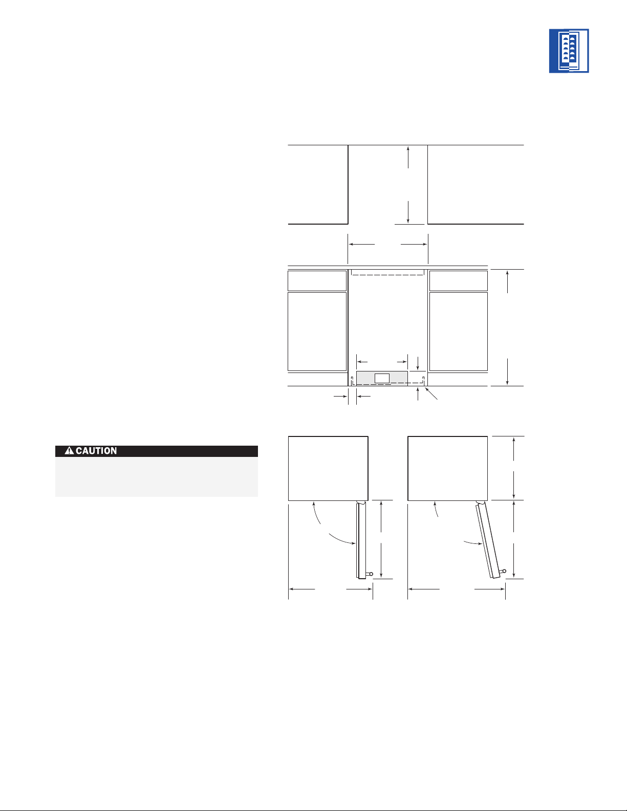
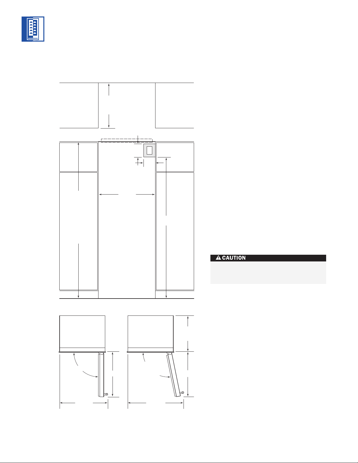
MODELS ICB424 AND ICB424FS
SITE PREPARATION
The Sub-Zero Model ICB424FS wine storage
unit is designed to be attractive in a stand
alone setting. It can also be slid into surround-
ing cabinetry with clearance dimensions
slightly different than the standard built-in
Model ICB424.
Make sure that the finished rough opening
where the Wine Storage unit is to be installed
is properly prepared. Refer to the Installation
Specifications illustration for rough opening
dimensions, door swing clearance and electri-
cal placement for Models ICB424 and
ICB424FS.
IMPORTANT NOTE:
To operate properly,
the door must open a minimum of 90 degrees.
Use a minimum 76 mm filler in corner installa-
tions to assure a 90-degree door opening.
Allow enough clearance in front of the unit
for full door swing.
IMPORTANT NOTE:
Make sure the floor under
the unit is level with the surrounding finished
floor.
3
MODELS ICB424 AND ICB424FS INSTALLATION
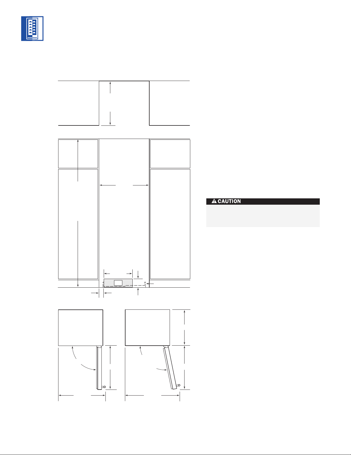
Do not load wine into the Wine Storage
unit until the installation is complete.
INSTALLATION SPECIFICATIONS
NOTE: Door swing clearances are based on stainless
steel door and handle dimensions.
MODELS
ICB424
ICB424FS
876 mm
ROUGH
OPENING
HEIGHT
870 mm
MINIMUM
HEIGHT
REQUIRED
ROUGH OPENING
WIDTH
610 mm MODEL ICB424
619 mm MODEL ICB424FS
394 mm
610 mm
ROUGH
OPENING
DEPTH
LOCATE ELECTRICAL
WITHIN SHADED AREA
E
114
mm
64 mm
606 mm
MODEL ICB424
ANTI-TIP BRACKET
MODEL ICB424FS
ANTI-TIP BRACKET
90˚
145˚
MAXIMUM
DOOR SWING
1118 mm
DOOR CLEARANCE
660 mm
DOOR CLEARANCE
644 mm 645 mm
FRONT VIEW
TOP VIEW

4
ELECTRICAL REQUIREMENTS
A 220-240 V AC, 50/60 Hz, 10 amp circuit
breaker and electrical supply are required. A
separate circuit, servicing only this appliance,
is required.
The power supply cord has a grounding plug,
which must be plugged into a mating ground -
ing-type wall recep tacle. Follow all National
Electrical codes and local codes and ordinances
when installing the receptacle. For location of
the electrical supply, refer to the Installation
Specifications illustration on page 3.
IMPORTANT NOTE:
For Models ICB424 and
ICB424FS, the outlet must be flush with the
back wall.
IMPORTANT NOTE:
A ground fault circuit
interrupter (GFCI) is not recommended and
may cause interruption of operation.
HOME ALARM SYSTEM
If a home alarm system is to be used, refer to
Home Alarm Connections on page 8. In addition
to operating power, the installer may also be
required to supply a home automation system
lead to the unit. This is for a low-voltage, low-
current signal similar to door and window
sensor signals. Common, normally open and
normally closed contact configurations are
provided.
Three 6 mm female spade connectors are
located in the compressor compartment and
are accessible behind the kickplate on Models
ICB424 and ICB424FS. A minimum of 914 mm
of lead wire should be provided for each
contact, exiting the back wall near the
electrical outlet.
MODELS ICB424 AND ICB424FS INSTALLATION
UNPACKING AND MOVING
Uncrate the unit, remove its wood base and
discard the shipping bolts that hold the wood
base to the bottom of the unit. Remove all
packing materials and tape.
IMPORTANT NOTE:
Do not discard the kick-
plate, anti-tip bracket and hardware. These
items will be needed for the installation.
All roller-assembly wine shelves should be
removed to reduce weight and prevent them
from rolling. To remove, pull the shelf out to
its full extension, gently and evenly lift up on
both sides of the front of the shelf and remove.
Reverse the procedure to reinstall the shelf.
Use an appliance dolly to move the Wine
Storage unit. Position the dolly at the back
of the unit to prevent damage to finished
surfaces.
Do not use an extension cord. Electrical
ground is required on this appliance.
Before moving the Wine Storage unit in
to position, protect any finished flooring
with appropriate materials and secure
the door closed.
MODELS
ICB424
ICB424FS
5
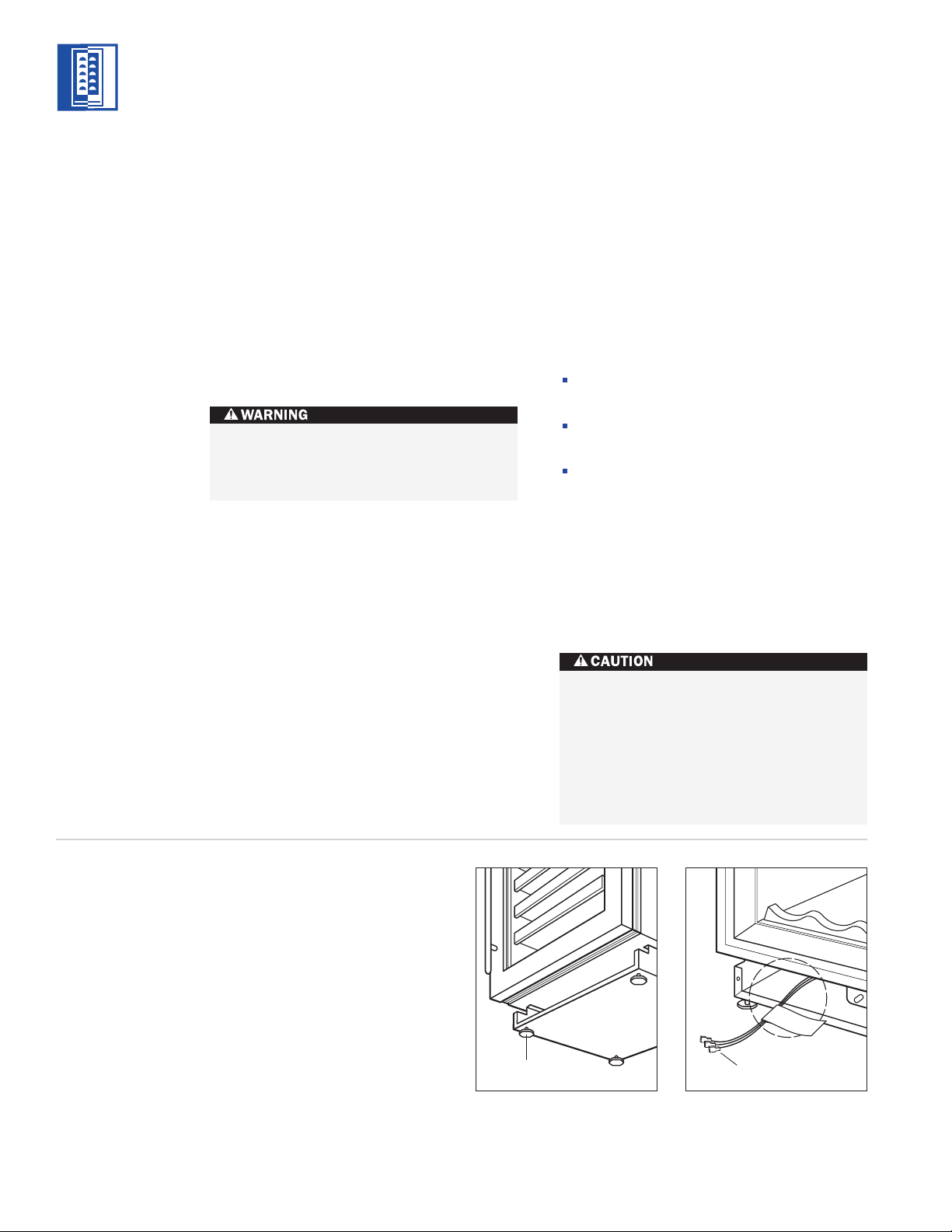
MODELS ICB424 AND ICB424FS INSTALLATION
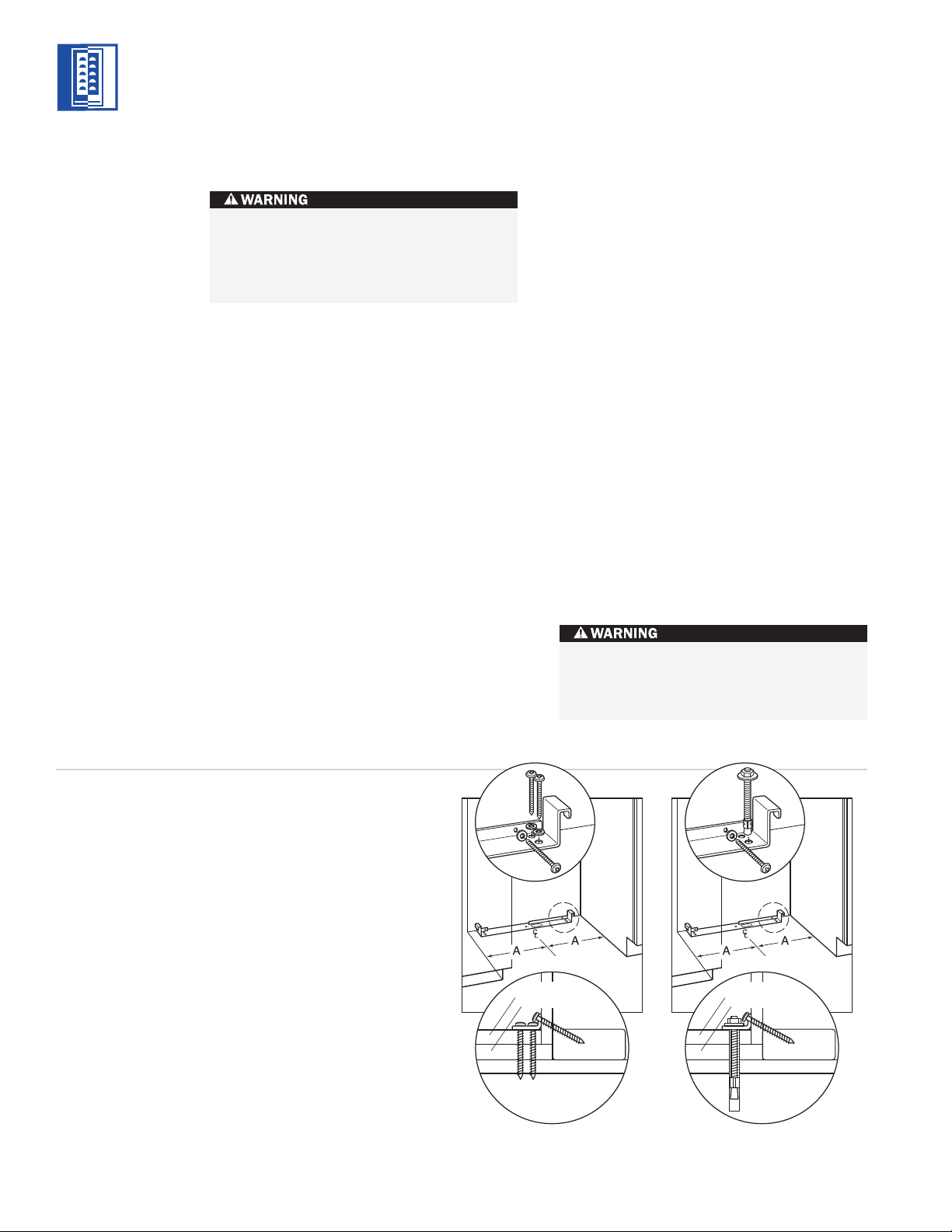
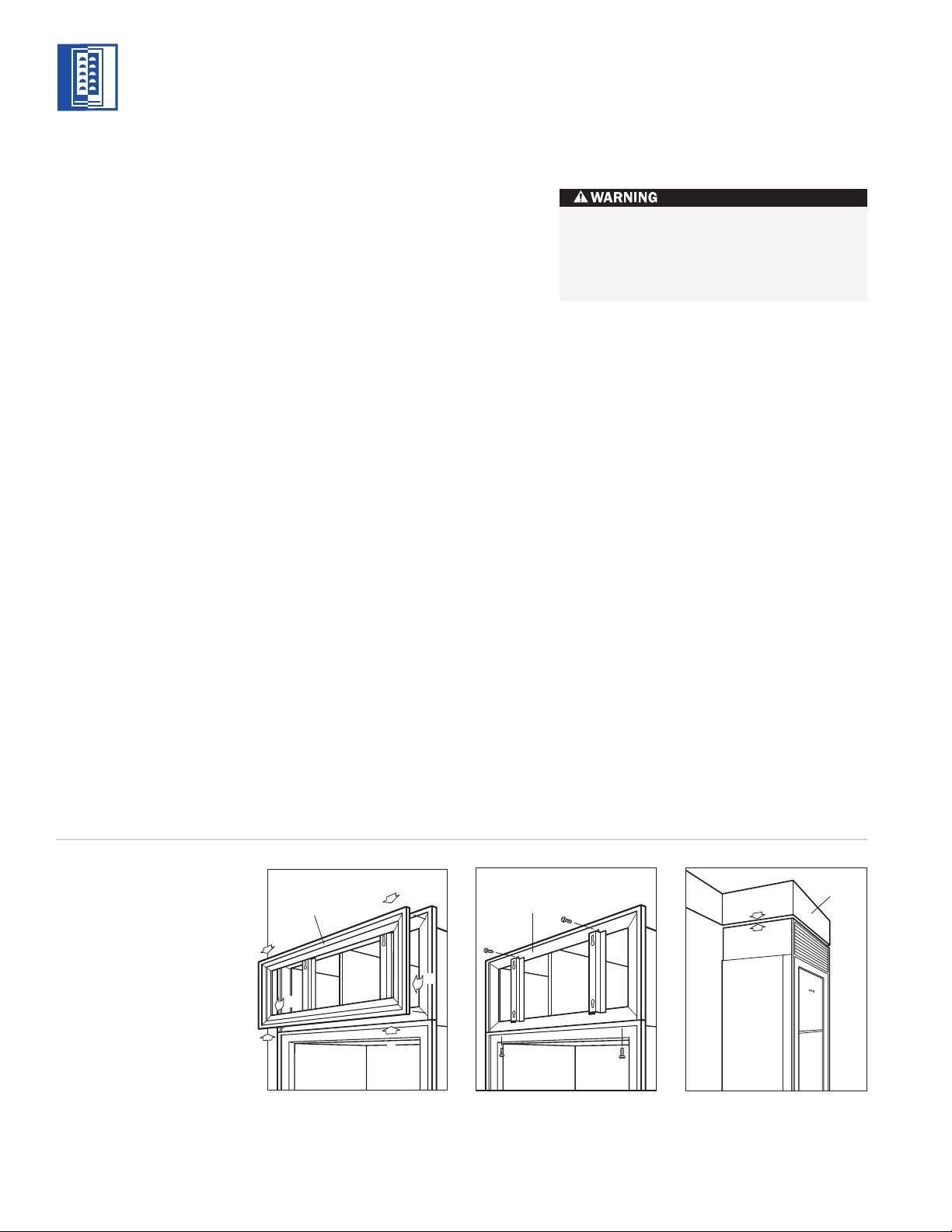
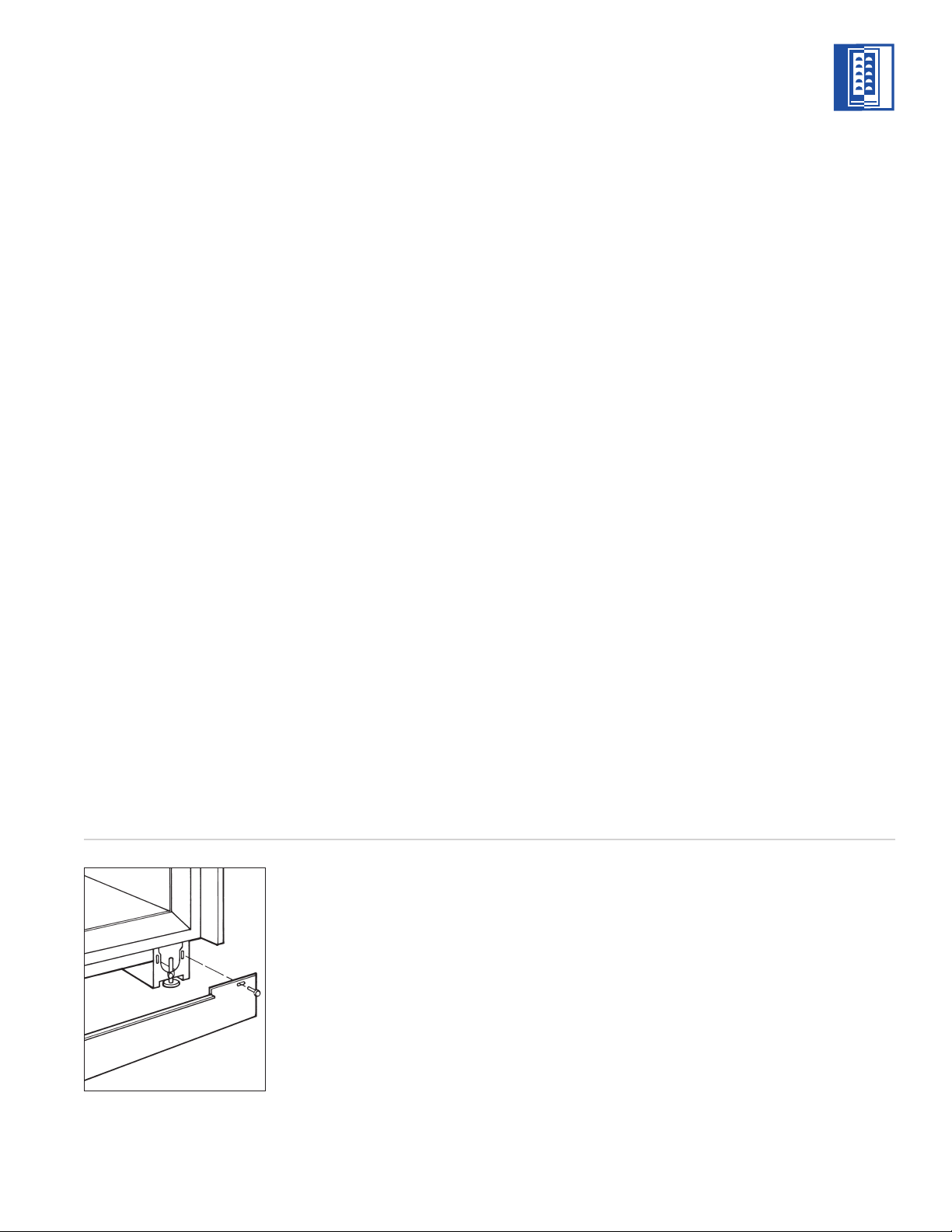
ANTI-TIP BRACKET
INSTALLATION
An anti-tip bracket and hardware is provided
with the Wine Storage unit. The anti-tip
bracket must be installed on a solid base to
prevent tipover in case several loaded wine
shelves are extended at the same time.
MODEL ICB424
The anti-tip bracket should be attached to the
wall behind the unit with the bracket flange
located immediately above the top of the unit.
Refer to illustration 1 below.
A smaller metal ‘countertop’ bracket is also
provided with the Model ICB424, for installa-
tions that need to be modified to provide a
secure surface for attaching the bracket. This
bracket will secure the front of the unit to the
underside of the countertop, above the unit.
Refer to illustration 2.
MODEL ICB424FS
If you are installing the Model ICB424FS in a
space deeper than 625 mm, the anti-tip bracket
must be installed no more than 625 mm deep,
so it engages the unit properly. It is important
that this measurement be made from the front
surface of the door, to the back of the anti-tip
bracket. Refer to illustration 3 below.
To prevent the unit from tipping forward
and provide a stable installation, the unit
must be secured in place with the anti-tip
bracket.
6 mm
Anti-Tip
Bracket
Countertop
Bracket
Anti-Tip Bracket
Illus. 1 Illus. 2 Illus. 3
MODELS
ICB424
ICB424FS
Installation for Concrete Wedge Anchors:
1)
Drill a 10 mm diameter hole any depth
exceeding the minimum embedment.
Clean the hole or continue drilling addi-
tional depth to accommodate drill fines.
Use a carbide drill bit.
2)
Assemble the washer and nut flush with the
end of anchor to protect threads. Drive the
anchor through the material to be fastened
until the washer is flush with the surface
material.
3)
Expand the anchor by tightening the nut
3–5 turns past hand-tight position or to
34 newtons of torque.
6
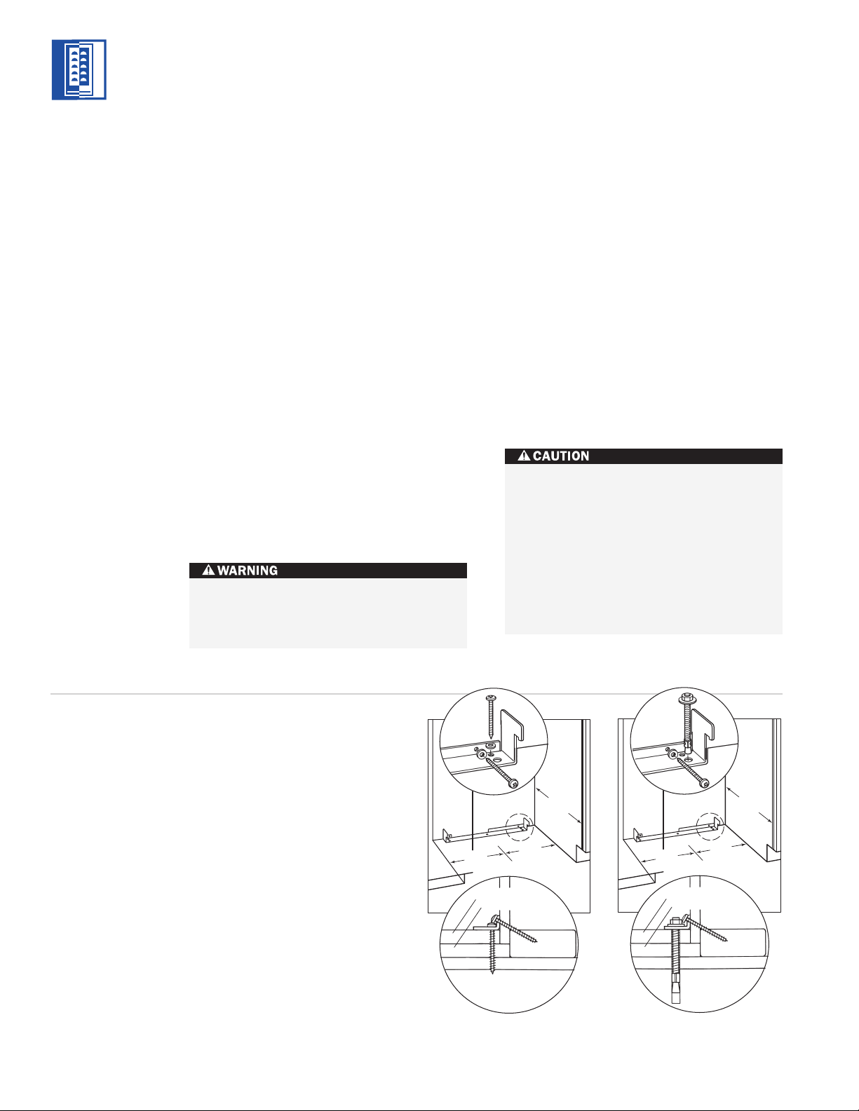
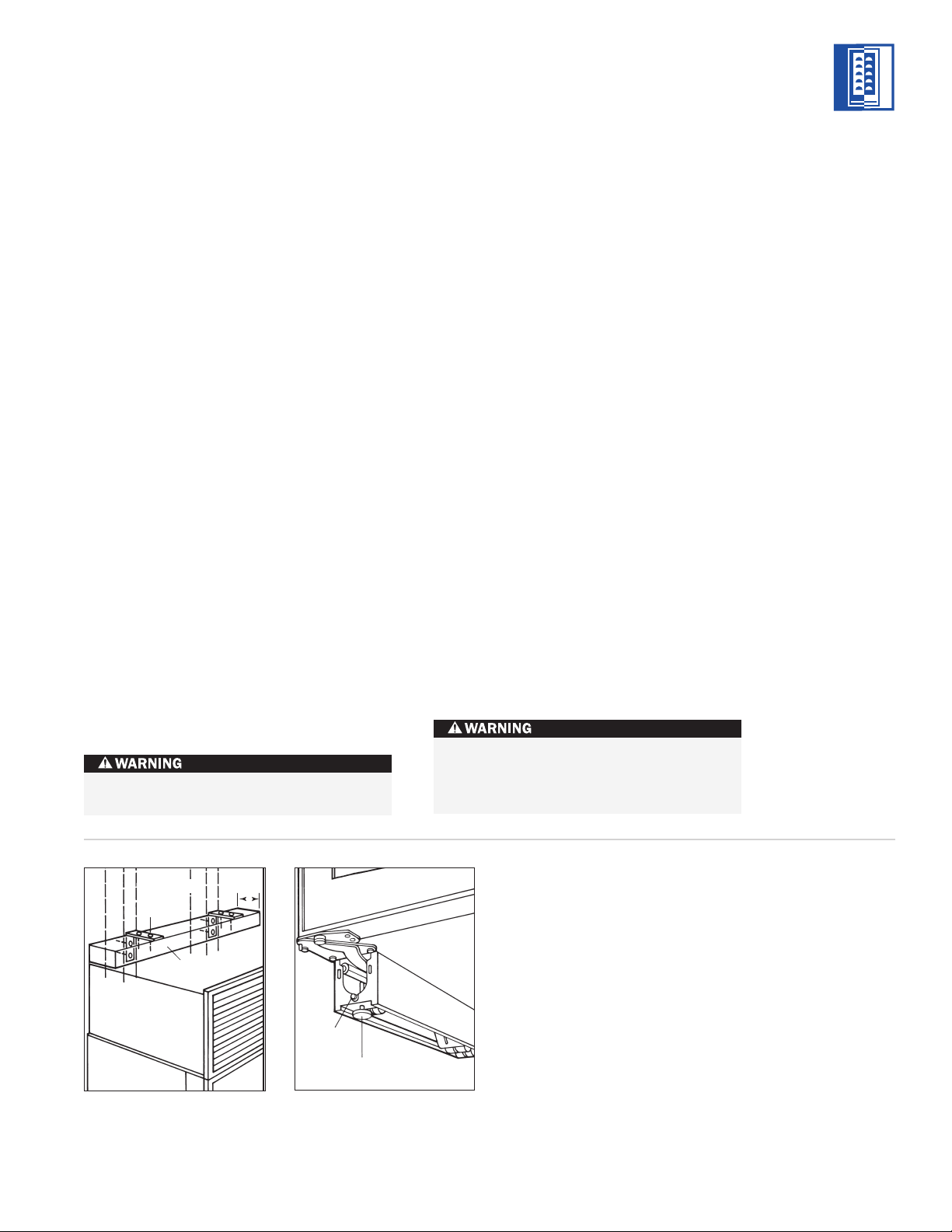
MODELS ICB424 AND ICB424FS INSTALLATION
ANTI-TIP BRACKET
INSTALLATION
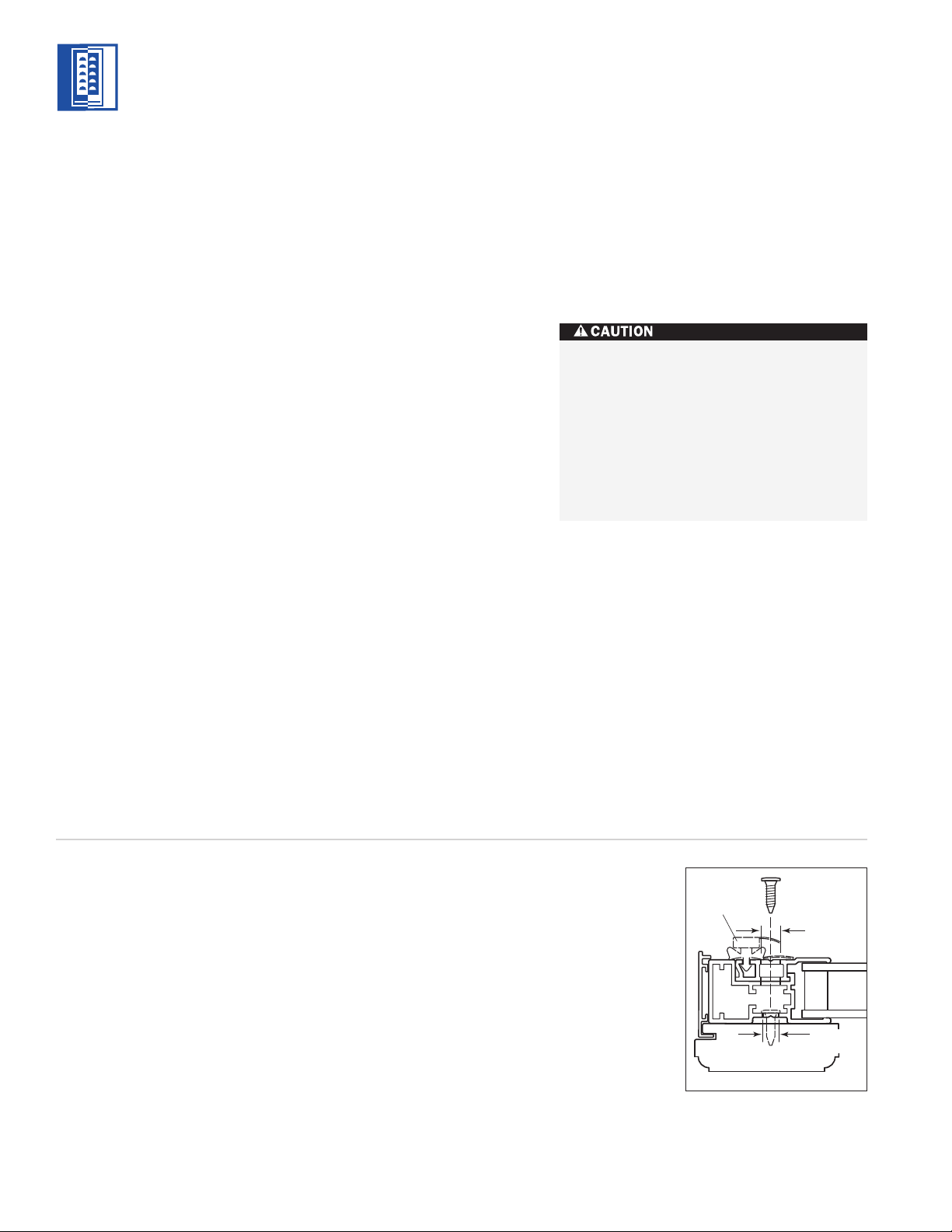
WOOD FLOOR APPLICATIONS
Use the four #12 x 64 mm wood screws and
the four 6 mm flat washers provided. Drill pilot
holes 5 mm diameter maximum, and be sure
that the screws penetrate through the flooring
material and into the wall plate a minimum of
19 mm. Be sure that the screws hold tight.
Refer to illustration 4 below.
CONCRETE FLOOR APPLICATIONS
Use the two 10 mm x 95 mm concrete wedge
anchors, two #12 x 64 mm wood screws and
two 6 mm flat washers provided. Be sure that
the anchors and screws hold tight. Refer to
illustration 5 below.
IMPORTANT NOTE:
In some installations
the subflooring or finished floor may require
angling the wood screws used to fasten the
anti-tip bracket to the back wall. Refer to
illustrations 4 and 5.
310
mm
310
mm
610
mm
C
L
WOOD FLOOR
Finished Flooring
Underlayment
Sub Flooring
Wall Plate
610
mm
C
L
CONCRETE
FLOOR
Finished Flooring
Underlayment
Sub Flooring
Wall Plate
38
mm
min
310
mm
310
mm
Illus. 4 Illus. 5
Make sure that there are no electrical
wires in the area which the screws could
penetrate.
Always wear safety glasses and use other
necessary protective devices or apparel
when installing or working with anchors.
Anchors are not recommended for use in
lightweight masonry material such as
block or brick, or for use in new concrete
which has not had sufficient time to cure.
The use of core drills is not recommended
to drill holes for the anchors.
MODELS
ICB424
ICB424FS

7
MODELS ICB424 AND ICB424FS INSTALLATION
LOCK INSTALLATION
IMPORTANT NOTE:
If you are adding an
accessory lock kit to your Wine Storage unit,
it should be installed before you position the
unit. Installation instructions are included with
the lock kit.
For Model ICB424, the lock is attached to the
bottom of the metal door frame. The decora-
tive door panel is not involved in the installa-
tion or operation of the lock. The catch portion
of the lock is attached to the bottom of the
appliance cabinet in pre-punched holes. When
installing the lock kit, it may be helpful to tip
the unit on its back for easier access.
POSITION THE UNIT
IMPORTANT NOTE:
If for any reason the Wine
Storage unit has been laid on its back or side,
you must allow the unit to stand upright for
a minimum of 24 hours before connecting
power.
Plug the power supply cord into the 10 amp
grounded electrical outlet. With power applied
to the appliance, check for lighting and cooling
before going any further. Once you are satis-
fied that the unit is operating properly, shut
off power to the electrical outlet at the circuit
breaker and proceed.
If a home alarm system is to be used with the
Wine Storage unit, the lead wires should be
threaded into the compressor compartment
before you position the unit. See Home Alarm
Connections on page 8, for the location of
these lead wires. After the unit is in position,
the alarm wiring can be completed from the
front.
Pre-level the Wine Storage unit before sliding
it into position. Leveling cannot be completed
with the unit pushed back in the installation
opening.
For Model ICB424FS, adust the leveling legs
so the top of the unit is no more than 879 mm
above the floor. This is to allow the unit to
engage the anti-tip bracket properly. Center the
Model ICB424FS in front of the anti-tip bracket.
Slide the unit into position, making sure the
anti-tip bracket is engaged properly.
IMPORTANT NOTE:
When the Wine Storage
unit is installed, the anti-tip bracket will be
positioned just below the engaging bracket
on the unit. It is not necessary to raise the
unit up so that it locks into the anti-tip bracket,
but the unit must be in alignment with the
anti-tip bracket.
The Wine Storage unit provides the best
access to its contents when the front surface
of the door panel extends out from surround-
ing cabinets approximately 6 mm. For Model
ICB424FS, if there are no surrounding cabinet
surfaces to gauge depth, slide the unit back
until it engages the anti-tip bracket.
IMPORTANT NOTE:
The floor under the Wine
Storage unit must be at the same level as the
surrounding finished floor to allow for removal
of the unit for servicing.
Shut off the power to the electrical outlet.
MODELS
ICB424
ICB424FS
8
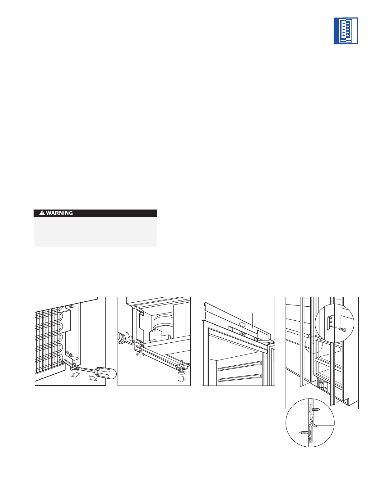
LEVEL THE UNIT
Using an adjustable wrench or pliers, turn
each of the four leveling legs clockwise to raise
the unit and counterclockwise to lower the
unit. For the location of the leveling legs, see
illustration 6 below.
For Model ICB424, the countertop bracket
should be used to make a solid installation.
Refer to illustration 2 on page 5. If this is not
possible, wedge shims along the sides and
top.
MODELS ICB424 AND ICB424FS INSTALLATION
Leveling Legs
Home Alarm
Connections
Illus. 6 Illus. 7
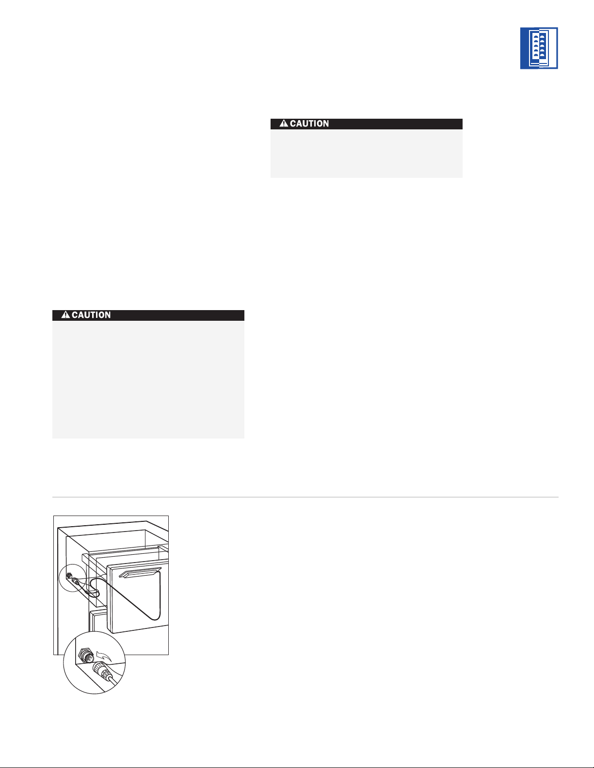
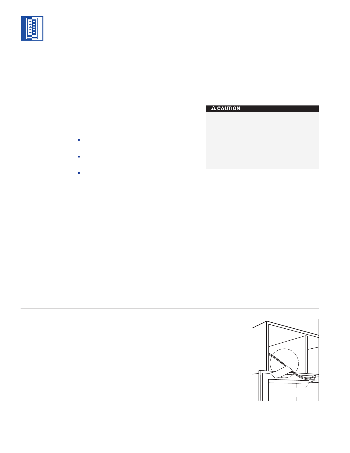
HOME ALARM CONNECTIONS
Before the kickplate is installed, all necessary
wiring connections in the compressor compart-
ment should be completed.
If a home alarm system is to be installed on
the Wine Storage unit, the connections should
be made using the logic supplied with the
alarm specifications. See illustration 7 below
for the appliance lead locations, and refer to
the following for color codes:
Normally open contacts – white with red
stripe wire
Normally closed contacts – white with blue
stripe wire
Common – gray with white stripe wire
Use the 6 mm spade terminals or wire nuts
provided to make the proper wiring connec-
tions.
IMPORTANT NOTE:
If you are not responsible
for alarm system connection, this information
should be supplied to the home security
system contractor.
To reduce the possibility of the unit
tipping forward, the front leveling legs
must be in contact with the floor.
The alarm circuit in the unit is intended as
a low-voltage, low-current device only. It
should not be used to switch line power.
Any unused terminals should be
completely insulated and all wires should
be secured away from conductive or
moving components.
MODELS
ICB424
ICB424FS
9
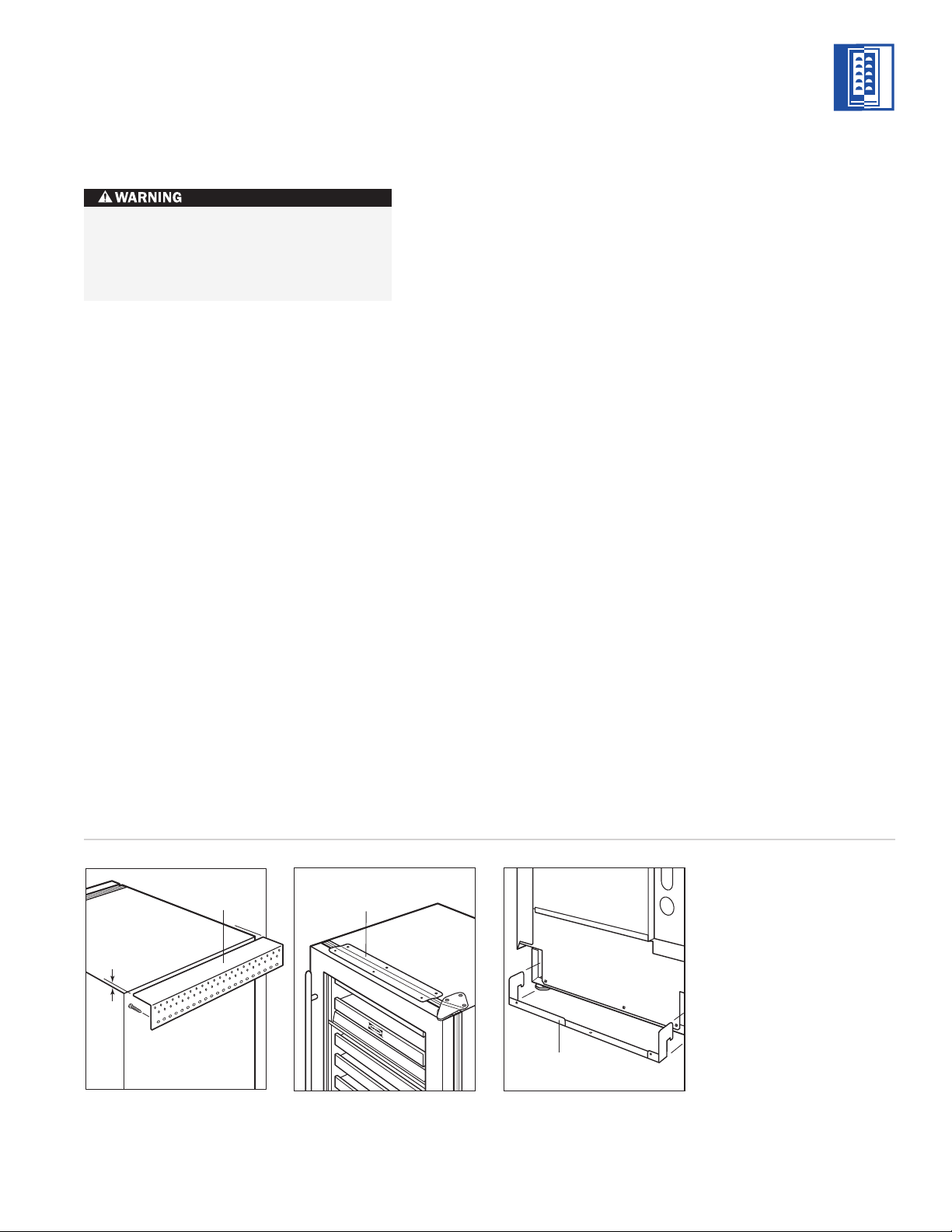
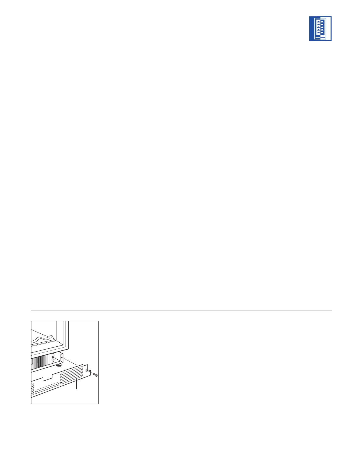
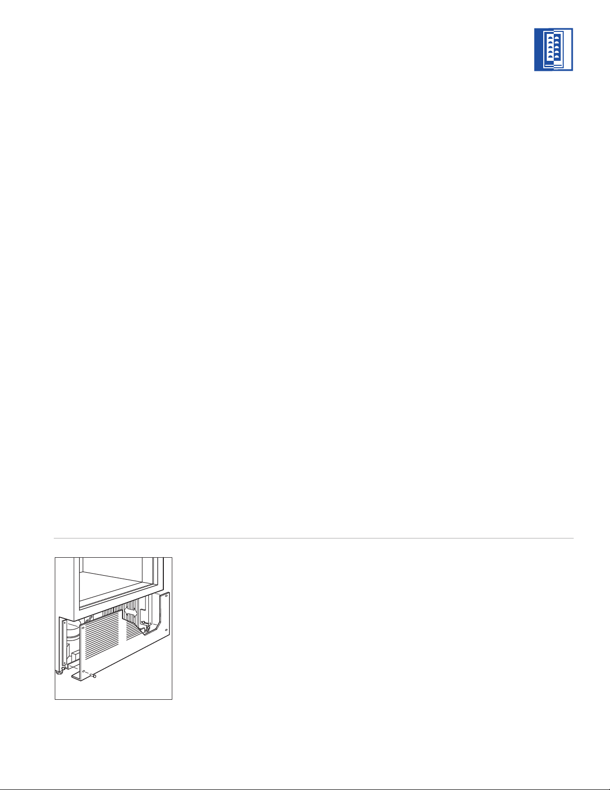
KICKPLATE INSTALLATION
Once the unit is leveled and wiring connections
made, the kickplate can be installed. Use the
two #10 x 13 mm stainless steel screws that
are provided with the kickplate. Refer to illus-
tration 8 below.
IMPORTANT NOTE:
The kickplate must be
removed for servicing. The floor cannot inter-
fere with removal. The louvered section of the
kickplate must not be covered so as to prevent
air circulation.
Turn power back on to the electrical outlet.
MODELS ICB424 AND ICB424FS INSTALLATION
Kickplate
Illus. 8
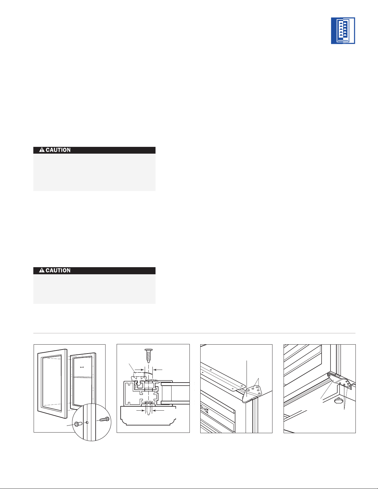
DOOR PANELS – MODEL ICB424
Model ICB424 is offered in two design applica-
tions; stainless steel (/S) and overlay (/O). Each
of these designs are available as a glass door
(G) model.
The stainless steel Model ICB424 is available in
the classic finish only and is shipped from the
factory with the decorative stainless steel door
panel and matching handle in place.
The overlay Model ICB424/O is designed to
accept a decorative door panel to match
surrounding cabinetry. The door panel and
the handle will be provided by the customer.
The solid door Model ICB424S—with no glass
window—requires a different door panel than
the glass door design.
Before beginning installation, check for the
correct components for the fit and finish
desired. All overlay doors require a decorative
panel 603 mm by 764 mm and a minimum
16 mm thick.
If you have questions, contact your Sub-Zero
dealer or cabinet supplier. Additional panel
information can be found in the Sub-Zero
Design Guide.
PANEL
DESIGN
Additional panel
design information
can be found in
the Sub-Zero
Design Guide.
Check our website
at subzero.com.
MODELS
ICB424
ICB424FS

10
MODELS ICB424 AND ICB424FS INSTALLATION
MODELS
ICB424
ICB424FS
PANEL
DESIGN
Additional panel
design information
can be found in
the Sub-Zero
Design Guide.
Check our website
at subzero.com.
IMPORTANT NOTE:
After the first three or
four mounting screws are in place, but not
completely tightened, close the door and check
your panel fit. This is the time to make small
adjustments. Once you are satisfied with the
appearance, open the door and apply the
remainder of the screws. Check all screws for
tightness.
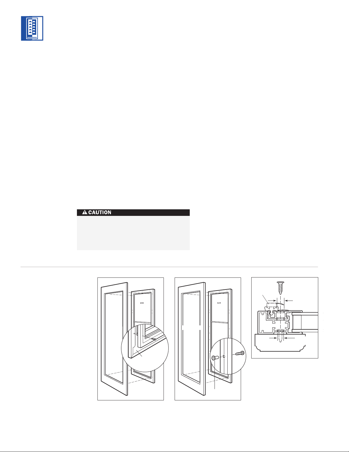
The metal frame on the glass door has
numerous mounting holes on each side of the
door. This is to accommodate the Sub-Zero
accessory handles and provide for easy attach-
ment of the handle through the door frame.
If you choose not to use the pre-drilled handle
mounting holes, it will be necessary to fasten
the handle from the rear of the door panel
only, or drill one or more additional holes
through the metal frame of the glass door.
Illustration 10 on page 11 shows how this
hole passes through the door frame. The hole
center is on the small locator groove in the
front of the frame. A 6 mm diameter hole is
made in the front wall of the extrusion and
an 11 mm diameter hole through the rest
of the frame.
OVERLAY DOOR PANELS
OVERLAY GLASS DOOR – MODEL ICB424
Inspect the door panel for the minimum 16 mm
thickness, the finished inside edge and the 5 kg
weight limit. See the Wine Storage section of
the Sub-Zero Design Guide for additional panel
information.
Decide if the handle will be attached through
the glass door frame or just through the deco-
rative door panel. If it is just through the door
panel, the handle must be attached first.
Decorative panels are attached to the Model
ICB424 door using #8 x 16 mm square drive
screws passing through the door frame from
the rear, behind the gasket into the panel. The
door panel is marked for screw locations by
the use of ‘tenon centers’, which are temporar-
ily inserted into the 6 mm diameter holes in
the front of the glass door frame. Refer to illus-
tration 9 on page 11.
With the Wine Storage unit secured in position
and the door closed, the panel is held in the
desired position on the door and rapped by
hand from the front, putting center marks on
the rear surface of the panel. If the door panel
is made of such a material that pre-drilling is
needed, all of the mounting holes should be
marked. If not, only enough holes to hold the
panel in place temporarily, are necessary.
The door panel is then lowered from the door
frame, tenon centers removed, the door
opened and the screws driven into the panel
through the black tape on the door frame,
using the center marks to locate the screws.
The screw holes inside the door are hidden
under a cover flap on the door gasket. It is
necessary to lift the flap to insert the screws.
Use as many screws as necessary to hold the
door panel in place properly.
The wine storage unit door is made with
a sealed double wall tempered glass core.
The drill must not contact this core when
drilling. Be sure the hole is centered on
the small groove in the front of the door
frame and the drill passes squarely
through the frame. If you are inexperi-
enced with drilling, fasten the handle
from the rear of the door panel only.
Door
Frame
Overlay
Panel
Tenon Center
6 mm
Diameter
11 mm
Diameter
Glass
Gasket
Illus. 9 Illus. 10
IMPORTANT NOTE:
Install screws in all the
mounting holes in the door frame. The nature
of the door panel with a narrow outer rim and
no connecting center member requires the
support provided by the glass door.
After the door panel installation is complete,
apply the cover patches or plugs provided over
the holes on the inside surface of the door.
OVERLAY SOLID DOOR – MODEL ICB424
IMPORTANT NOTE:
The solid door panel for
the Model ICB424 must be a minimum of 16
mm thick and cannot exceed 9 kg.
Installation of the solid door panel is the same
as the door panel for a glass door model.
HINGE ADJUSTMENT
IMPORTANT NOTE:
The Wine Storage unit
must be installed and leveled before door
hinge adjustments can be made.
The top and bottom cabinet hinges on Models
ICB424 and ICB424FS are held in place with
three permanent adjustment screws and two
shipping screws. Refer to illustrations 11 and
12 below. The shipping screws must be
removed and discarded to adjust the door
alignment and fit. If no adjustments are neces-
sary, it is recommended that all five screws
remain in place.
On the Model ICB424FS, only the bottom door
hinge can be adjusted. Remove and discard
the two shipping screws and loosen the three
hinge screws to adjust the door. Refer to
illustration 12.
COMPLETING THE INSTALLATION
IMPORTANT NOTE:
When you have
completed the installation of the Model ICB424
or ICB424FS Wine Storage unit, refer to pages
34–35 for the Installation Checklist and Service
Information.
A solid panel must not be installed on a
glass door unit, as this may cause
moisture to form behind the panel.
The cover patches or plugs are part of the
insulation system on the door of the Wine
Storage unit. Be sure to cover all the
holes in the door that were used.
11
MODELS ICB424 AND ICB424FS INSTALLATION
MODELS
ICB424
ICB424FS
Top Door Hinge
Shipping
Screws
Shipping
Screws
Bottom
Door Hinge
Illus. 11 Illus. 12
12
SITE PREPARATION
Make sure that the finished rough opening
where the Wine Storage unit is to be installed
is properly prepared. Refer to the Installation
Specifications illustration for rough opening
dimensions, door swing clearance and electri-
cal placement for Models ICB427 and ICB427R.
IMPORTANT NOTE:
To operate properly, the
door must open a minimum of 90 degrees.
Use a minimum 51 mm filler in corner installa-
tions to assure a 90-degree door opening.
Allow enough clearance in front of the unit for
full door swing.
IMPORTANT NOTE:
Make sure the floor under
the unit is level with the surrounding finished
floor.
MODELS ICB427 AND ICB427R INSTALLATION
686 mm
ROUGH OPENING WIDTH
635 mm
ROUGH
OPENING
DEPTH
606 mm
90˚
105˚
MAXIMUM
DOOR SWING
889 mm
DOOR CLEARANCE
711 mm
DOOR CLEARANCE
648 mm 648 mm
394 mm
LOCATE ELECTRICAL
WITHIN SHADED AREA
E
114
mm
64 mm
ANTI-TIP BRACKET
FRONT VIEW
TOP VIEW
2032 mm
ROUGH OPENING
HEIGHT
TO FINISHED
FLOORING
2019 mm
MIN HEIGHT
REQUIRED
Do not load wine into the Wine Storage
unit until the installation is complete.
MODELS ICB427 AND ICB427R
INSTALLATION SPECIFICATIONS
NOTE: Door swing clearances are based on stainless
steel door and handle dimensions.
MODELS
ICB427
ICB427R

13
ELECTRICAL REQUIREMENTS
A 220-240 V AC, 50/60 Hz, 10 amp circuit
breaker and electrical supply are required. A
separate circuit, servicing only this appliance,
is required.
The power supply cord has a grounding plug,
which must be plugged into a mating ground -
ing-type wall recep tacle. Follow all National
Electrical codes and local codes and ordi-
nances when installing the receptacle. For
location of the electrical supply, refer to
the Installation Specifications illustration on
page 12.
IMPORTANT NOTE:
A ground fault circuit
interrupter (GFCI) is not recommended and
may cause interruption of operation.
HOME ALARM SYSTEM
If a home alarm system is to be used, refer to
Other Wiring Connections on page 18. In
addition to operating power, the installer may
also be required to supply a home automation
system lead to the unit. This is for a low-
voltage, low-current signal similar to door and
window sensor signals. Common, normally
open and normally closed contact configura-
tions are provided.
Three 6 mm female spade connectors are
located in the compressor compartment and
are accessible behind the kickplate/grille on
Models ICB427 and ICB427R. A minimum of
914 mm of lead wire should be provided for
each contact, exiting the back wall near the
electrical outlet.
UNPACKING AND MOVING
Uncrate the unit, remove its wood base and
discard the shipping bolts that hold the wood
base to the bottom of the unit. Remove all
packing materials and tape.
IMPORTANT NOTE:
Do not discard the
kickplate/grille, anti-tip bracket and hardware.
These items will be needed for the installation.
All roller-assembly wine shelves should be
removed to reduce weight and prevent them
from rolling. To remove, pull the shelf out to
its full extension, gently and evenly lift up on
both sides of the front of the shelf and remove.
Reverse the procedure to reinstall the shelf.
Retract the front leveling legs to allow you to
move the unit more easily during installation.
You will extend the leveling legs when the unit
is in its final position to reduce the possibility
of the unit tipping forward.
Use an appliance dolly to move the Wine
Storage unit. Position the dolly at the side of
the unit to prevent damage to finished
surfaces.
MODELS ICB427 AND ICB427R INSTALLATION
Before moving the Wine Storage unit into
position, protect any finished flooring
with appropriate materials.
Do not use an extension cord. Electrical
ground is required on this appliance.
MODELS
ICB427
ICB427R
WOOD FLOOR APPLICATIONS
Use the six #12 x 64 mm wood screws and the
six 6 mm flat washers provided. Drill pilot
holes 5 mm diameter maximum, and be sure
that the screws penetrate through the flooring
material and into the wall plate a minimum of
19 mm. Be sure that the screws hold tight.
Refer to illustration 1 below.
CONCRETE FLOOR APPLICATIONS
Use the two 10 mm x 95 mm concrete wedge
anchors, two #12 x 64 mm wood screws and
two 6 mm flat washers provided. Be sure that
the anchors and screws hold tight. Refer to
illustration 2 below.
IMPORTANT NOTE:
In some installations the
subflooring or finished floor may require
angling the wood screws used to fasten the
anti-tip bracket to the back wall. Refer to illus-
trations 1 and 2 below.
14
MODELS ICB427 AND ICB427R INSTALLATION
ANTI-TIP BRACKET
INSTALLATION
An anti-tip bracket and hardware is provided
with the Wine Storage unit. The anti-tip
bracket must be installed on a solid base to
prevent tipover in case several loaded wine
shelves are extended at the same time.
If you are installing the Model ICB427 or
ICB427R in a space deeper than 610 mm, the
anti-tip bracket must be installed no more than
610 mm deep, so it engages the unit properly.
It is important that this measurement be made
from the front of the unit without panels, to
the back of the anti-tip bracket.
To prevent the unit from tipping forward
and provide a stable installation, install
the anti-tip bracket and extend the front
leveling legs to the floor.
Make sure that there are no electrical
wires in the area which the screws could
penetrate.
MODELS
ICB427
ICB427R
WOOD FLOOR
Finished Flooring
Underlayment
Subflooring
Wall Plate
Finished Flooring
Underlayment
Subflooring
Wall Plate
CONCRETE
FLOOR
38
mm
min
Illus. 1 Illus. 2
SPECIFICATIONS
Dimension A 343 mm
15
MODELS ICB427 AND ICB427R INSTALLATION
POSITION THE UNIT
IMPORTANT NOTE:
For Model ICB427R, the
top drawer has a control cable that needs to be
disconnected before removing this drawer.
Refer to illustration 3 below for placement and
how to disconnect this fitting.
For Model ICB427R, the drawers should be
placed aside until you are ready for installation
of the door and drawer panels.
IMPORTANT NOTE:
When two Model ICB427,
ICB427R or Integrated units are installed closer
than 51 mm to one another, it is necessary to
use the Sub-Zero dual installation heater kit.
Contact your Sub-Zero dealer for the proper
components and additional instructions. The
heater plate from this dual installation heater
kit must be attached to the left side exterior of
the right hand unit before the unit is slid into
position.
Illus. 3
Always wear safety glasses and use other
necessary protective devices or apparel
when installing or working with anchors.
Anchors are not recommended for use in
lightweight masonry material such as
block or brick, or for use in new concrete
which has not had sufficient time to cure.
The use of core drills is not recommended
to drill holes for the anchors.
Installation for Concrete Wedge Anchors:
1)
Drill a 10 mm diameter hole any depth
exceeding the minimum embedment. Clean
the hole or continue drilling additional
depth to accommodate drill fines. Use a
carbide drill bit.
2)
Assemble the washer and nut flush with the
end of anchor to protect threads. Drive the
anchor through the material to be fastened
until the washer is flush with the surface
material.
3)
Expand the anchor by tightening the nut
3–5 turns past hand-tight position or to 34
newtons of torque.
Before moving the Wine Storage unit into
position, secure the door closed. Remove
the drawers of the Model ICB427R.
MODELS
ICB427
ICB427R
OPTIONAL
COMPONENTS
Optional installa-
tion components
are available
through your
Sub-Zero dealer.
You can also visit
our website at
subzero.com.

16
POSITION THE UNIT
IMPORTANT NOTE:
If you are adding an
accessory lock kit to your Model ICB427 or
ICB427R, the catch should be installed at the
top of appliance cabinet before you position
the unit. See Lock Installation on page 23.
Installation instructions are included with the
lock kit.
Remove the decorative top and side moldings
and the kickplate/grille of the Wine Storage
unit.
IMPORTANT NOTE:
If for any reason the Wine
Storage unit has been laid on its back or side,
you must allow the unit to stand upright for a
minimum of 24 hours before connecting
power.
Plug the power supply cord into the 10 amp
grounded electrical outlet. With power applied
to the appliance, check for lighting and cooling
before going any further. Once you are satis-
fied that the unit is operating properly, shut off
power to the electrical outlet at the circuit
breaker and proceed.
If a home alarm system is to be used with the
Wine Storage unit, the lead wires should be
threaded into the compressor compartment
before you position the unit. See Other Wiring
Connections on page 18 for the location of
these lead wires. After the unit is in position,
the alarm wiring can be completed from the
front.
Pre-level the Wine Storage unit before rolling
into position. This is to allow the unit to
engage the anti-tip bracket properly.
Roll the unit into position, making sure the
anti-tip bracket is engaged properly. Screw the
front leveling legs out approximately 5 mm to
make any future adjustments easier.
IMPORTANT NOTE:
When the Wine Storage
unit is installed, the anti-tip bracket will be
positioned just below the engaging bracket on
the unit. It is not necessary to raise the unit up
so that it locks into the anti-tip bracket, but the
unit must be in alignment with the anti-tip
bracket.
IMPORTANT NOTE:
The floor under the Wine
Storage unit must be at the same level as the
surrounding finished floor to allow for removal
of the unit for servicing.
MODELS ICB427 AND ICB427R INSTALLATION
Shut off the power to the electrical outlet.
MODELS
ICB427
ICB427R
17
MODELS ICB427 AND ICB427R INSTALLATION
LEVEL THE UNIT
Level the unit by turning the front leveling legs
clockwise to raise the unit, or counterclockwise
to lower it. To assist you in adjusting the front
leveling legs up or down, use a standard
screwdriver blade and place it in the front
leveling leg as shown in illustration 4 below.
The rear leveling legs are adjusted from the
front of the base by turning the Phillips head
screw. Refer to illustration 5.
IMPORTANT NOTE:
The rear leveling legs will
only move 2 mm for every 18 revolutions on
the Phillips head screw. Do not over torque.
Use the lowest torque setting on any power
screwdriver. Do not turn the rear leveling legs
by hand. Damage will occur if you turn these
legs.
To reduce the possibility of the unit
tipping forward, the front leveling legs
must be in contact with the floor.
MOLDING INSTALLATION
The decorative white molding strips for the
side and top of Models ICB427 and ICB427R
can be snapped into place. The top molding
piece must be installed before the side
molding can be attached. For installation of the
top molding, refer to illustration 6 below. Refer
to illustration 7 for side molding installation.
For installations where units are side by side,
see Finished Wood Side Panels on page 23.
Top Molding
Illus. 4 Illus. 5 Illus. 6
Illus. 7
MODELS
ICB427
ICB427R
IMPORTANT NOTE:
If you are not responsible
for alarm system connection, this information
should be supplied to the home security
system contractor.
18
OTHER WIRING CONNECTIONS
Before the kickplate/grille is installed, all
necessary wiring connections in the compres-
sor compartment should be completed.
If the dual installation heater kit (#7007529) is
used with Model ICB427 or ICB427R, the power
supply leads should be connected according to
instructions included with the kit.
If a home alarm system is to be installed on
the Wine Storage unit, the connections should
be made using the logic supplied with the
alarm specifications. See illustration 8 below
for the appliance lead locations, and refer to
the following for color codes:
Normally open contacts – white with red
stripe wire
Normally closed contacts – white with blue
stripe wire
Common – gray with white stripe wire
Use the 6 mm spade terminals or wire nuts
provided to make the proper wiring connec-
tions.
MODELS ICB427 AND ICB427R INSTALLATION
The alarm circuit in the unit is intended as
a low-voltage, low-current device only. It
should not be used to switch line power.
Any unused terminals should be
completely insulated and all wires should
be secured away from conductive or
moving components.
Home Alarm
Connections
Illus. 8
MODELS
ICB427
ICB427R
OPTIONAL
COMPONENTS
Optional installa-
tion components
are available
through your
Sub-Zero dealer.
You can also visit
our website at
subzero.com.
19
KICKPLATE / GRILLE INSTALLATION
Once the unit is leveled and wiring connec-
tions made, the kickplate/grille can be
installed.
IMPORTANT NOTE:
The kickplate/grille must
be removed for servicing. The floor cannot
interfere with removal. The louvered section of
the kickplate/grille must not be covered so as
to prevent air circulation.
For Models ICB427 and ICB427R, there is some
adjustment to the mounting assembly so that
the kickplate/grille can fit flush with the
surrounding area. Refer to illustration 9 below.
IMPORTANT NOTE:
The unit must be allowed
to have ventilation through the fins of the kick-
plate/grille. You may cover the solid area, but
do not block the fins. For Model ICB427R, the
lower drawer panel may hang in front of the
fins, but your baseboard molding must not
cover them.
Turn power back on to the electrical outlet.
DOOR PANELS
Models ICB427 and ICB427R are available as a
glass door (G) or solid door (S) model. Each of
these Wine Storage units are set up at the job
site as either the stainless steel or integrated
design.
Classic stainless steel panels—available as
sales accessories—may be configured several
ways and are shipped separately. Stainless
steel panels are shipped with matching
handles in place.
The integrated design uses custom wood or
other decorative panels and handles provided
by the customer.
Model ICB427R requires solid panels on the
drawers that may match the door panel, or be
complementary. The Model ICB427R stainless
steel drawer panel set and stainless steel door
panel are ordered and shipped as two items.
The solid door Model ICB427S or ICB427RS—
with no glass window—requires a different
door panel than the glass door design.
Before beginning installation, check for the
correct components for the fit and finish
desired. The door and drawers (Model
ICB427R) require a decorative panel that is a
minimum 16 mm thick.
If you have questions, contact your Sub-Zero
dealer or cabinet supplier. Additional panel
information can be found in the Sub-Zero
Design Guide.
MODELS ICB427 AND ICB427R INSTALLATION
Illus. 9
PANEL
DESIGN
Additional panel
design information
can be found in
the Sub-Zero
Design Guide.
Check our website
at subzero.com.
MODELS
ICB427
ICB427R
20
STAINLESS STEEL DOOR PANEL
Before installing the stainless steel door panel,
check the panel carefully. Options are available
for kickplate/grille height, overall height, door
swing and door lock.
The stainless steel panel is mounted to the
door by passing the #8–32 x 16 mm screws
provided, through holes in the door frame
from the rear, and into the threaded holes in
the door panel. Refer to illustration 10 below.
The screw holes inside the door are hidden
under a cover flap on the door gasket. It is
necessary to lift the flap to insert the screws.
After the door panel installation is complete,
apply the cover patches or plugs provided over
the holes on the inside surface of the door.
For installation of stainless steel panels on
Model ICB427R drawers, see Model ICB427R
Drawer Panels on page 22.
OVERLAY GLASS DOOR PANEL
Inspect the door panel for the minimum 16
mm thickness, the greater width requirements
for the stiles (to cover the door hinges), and
the finished inside edge. The door panel has a
weight limit of 9 kg. See the Wine Storage
section of the Sub-Zero Design Guide for addi-
tional panel information.
Decide if the handle will be attached through
the glass door frame or just through the deco-
rative door panel. If it is just through the door
panel, the handle must be attached first.
If a lock is to be used, the body of the lock
should be installed on the door panel after the
panel is mounted.
Decorative panels are attached to the Model
ICB427 and ICB427R door using #8 x 16 mm
square drive screws passing through the door
frame from the rear, behind the gasket into the
panel. The door panel is marked for screw
locations by the use of ‘tenon centers’, which
are temporarily inserted into the 6 mm
diameter holes in the front of the glass door
frame. Refer to illustration 11 below.
Door
Frame
Stainless
Steel
Panel
Back of
Stainless Steel
Panel
Door
Frame
Integrated
Panel
Tenon Center
6 mm
Diameter
11 mm
Diameter
Glass
Gasket
Illus. 10 Illus. 11
Illus. 12
MODELS ICB427 AND ICB427R INSTALLATION
The cover patches or plugs are part of the
insulation system on the door of the Wine
Storage unit. Be sure to cover all the
holes in the door that were used.
MODELS
ICB427
ICB427R
PANEL
DESIGN
Additional panel
design information
can be found in
the Sub-Zero
Design Guide.
Check our website
at subzero.com.

21
With the Wine Storage unit secured in position
and the door closed, the panel is held in the
desired position on the door and rapped by
hand from the front, putting center marks on
the rear surface of the panel. If the door panel
is made of such a material that pre-drilling is
needed, all of the mounting holes should be
marked. If not, only enough holes to hold the
panel in place temporarily, are necessary.
The door panel is then lowered from the door
frame, tenon centers removed, the door
opened and the screws driven into the panel
through the black tape on the door frame,
using the center marks to locate the screws.
The screw holes inside the door are hidden
under a cover flap on the door gasket. It is
necessary to lift the flap to insert the screws.
Use as many screws as necessary to hold the
door panel in place properly.
IMPORTANT NOTE:
After the first three or
four mounting screws are in place, but not
completely tightened, close the door and check
your panel fit. This is the time to make small
adjustments. Once you are satisfied with the
appearance, open the door and apply the
remainder of the screws. Check all screws for
tightness.
The metal frame on the glass door has
numerous mounting holes on each side of the
door. This is to accommodate the Sub-Zero
accessory handles and provide for easy attach-
ment of the handle through the door frame.
If you choose not to use the pre-drilled handle
mounting holes, it will be necessary to fasten
the handle from the rear of the door panel
only, or drill one or more additional holes
through the metal frame of the glass door.
Illustration 12 on page 20 shows how this hole
passes through the door frame. The hole
center is on the small locator groove in the
front of the frame. A 6 mm diameter hole is
made in the front wall of the extrusion and a
11 mm diameter hole through the rest of the
frame.
IMPORTANT NOTE:
Install screws in all the
mounting holes in the door frame. The nature
of the door panel with a narrow outer rim and
no connecting center member requires the
support provided by the glass door.
After the door panel installation is complete,
apply the cover patches or plugs provided over
the holes on the inside surface of the door.
MODELS ICB427 AND ICB427R INSTALLATION
The cover patches or plugs are part of the
insulation system on the door of the Wine
Storage unit. Be sure to cover all the
holes in the door that were used.
The wine storage unit door is made with
a sealed double wall tempered glass core.
The drill must not contact this core when
drilling. Be sure the hole is centered on
the small groove in the front of the door
frame and the drill passes squarely
through the frame. If you are inexperi-
enced with drilling, fasten the handle from
the rear of the door panel only.
MODELS
ICB427
ICB427R
22
MODEL ICB427R DRAWER PANELS
IMPORTANT NOTE:
Drawer panels for Model
ICB427R must be a minimum of 16 mm thick
and cannot exceed 5 kg for each panel.
Remove the mounting hardware provided and
set aside. You should work on the back side of
each drawer panel and you should protect the
fronts of these panels.
Position the top edge of the drawer template
flush with the top edge of each drawer. For the
top drawer, there is only one place for the
lower mounting bracket to be placed. However,
depending on the depth of the lower drawer
panel, you have two options for placement of
the bracket. Refer to illustration 13 below.
Secure the template in place with tape or small
clamps and mark positions for your pilot holes.
Remove template. Drill pilot holes and place
the hardware in the proper place (dog-ear
bracket on top) and fasten securely with the #8
x 13 mm screws provided. See illustration 14.
To help with proper placement of drawer
panels, examine the lower panel mounting
bracket and determine which slotted holes to
use. Position screws into the lower portion of
the drawer that correspond with these slotted
holes. Leave these screws out a small distance
so they can help when you mount the drawer
panels to the drawer.
With the two brackets in place on the drawer
panel, engage the top dog-ear bracket first and
then the lower bracket onto the protruding
screws. You will have a 6 mm adjustment up
and down and side to side in each drawer
panel. Fasten all screws to the lower bracket to
secure the drawer panel.
IMPORTANT NOTE:
Once drawer panels have
been adjusted for proper spacing, be sure to
reconnect the control cable on the upper
drawer after you have installed the drawer.
Refer to illustration 3 on page 15.
SOLID DOOR PANE LS
IMPORTANT NOTE:
The solid door panel for
Models ICB427 and ICB427R must be a minimum
of 16 mm thick and cannot exceed 18 kg.
Installation of the solid door panel is the same
as the door panel for a glass door model.
MODELS ICB427 AND ICB427R INSTALLATION
A solid panel must not be installed on a
glass door unit, as this may cause
moisture to form behind the panel.
MODELS
ICB427
ICB427R
PANEL
DESIGN
Additional panel
design information
can be found in
the Sub-Zero
Design Guide.
Check our website
at subzero.com.
Back Of
Drawer Panel
Gap On Side
Edges Will Vary
According To
Design
Top Of Template
Flush With Top Of
Drawer Panel
Illus. 13 Illus. 14
23
FINISHED WOOD SIDE PANELS
Side panels for Models ICB427 and ICB427R
are not attached to the unit. You must securely
fasten the panels to adjacent cabinets and
floor.
Panels should be fastened to the floor and
walls using ‘L’ brackets (hardware not
provided). To help you move the unit into
place, rout out an area in the floor so the ‘L’
bracket will sit flush with the floor level.
Brackets and screws are provided for
mounting the unit to adjoining cabinets and
side panels. Each unit has four side-mounting
clips on each side.
IMPORTANT NOTE:
For installations where
you are not attaching to a side wall, or you are
installing two Model ICB427, ICB427R or Inte-
grated units together, you must remove the
side-mounting clips before moving the unit
into position. After removing the clips, replace
the screws into the appliance.
A dual installation heater kit (#7007529) is
necessary for anchoring two Model ICB427,
ICB427R or Integrated units together. Contact
your Sub-Zero dealer for details.
LOCK INSTALLATION
For Models ICB427 and ICB427R, the accessory
lock is attached to the decorative door panel
through a field-drilled hole in the panel. The
catch should be installed on the top of appli-
ance cabinet before the unit was moved into
position. Installation instructions are included
with the lock kit.
IMPORTANT NOTE:
For accessory stainless
steel panels requiring a lock, panels must be
ordered with the lock mounting hole pre-
drilled.
90-DEGREE
DOOR STOP
Models ICB427 and ICB427R have a 90-degree
door stop built into the hinge system. Use the
blade edge of a standard screwdriver and
rotate the brass cam in the center portion of
the hinge until you reach the stop. You must
make this adjustment to both the bottom and
top hinge. Refer to illustration 15 below.
COMPLETING THE INSTALLATION
IMPORTANT NOTE:
When you have
completed the installation of the Model ICB427
or ICB427R Wine Storage unit, refer to pages
34–35 for the Installation Checklist and Service
Information.
MODELS ICB427 AND ICB427R INSTALLATION
Illus. 15
MODELS
ICB427
ICB427R
OPTIONAL
COMPONENTS
Optional installa-
tion components
are available
through your
Sub-Zero dealer.
You can also visit
our website at
subzero.com.
24
SITE PREPARATION
Make sure that the finished rough opening
where the Wine Storage unit is to be installed
is properly prepared. Refer to the Installation
Specifications illustration for rough opening
dimensions, door swing clearance and electri-
cal placement for Model ICB430.
If you are installing two Model ICB430 units
side by side, or a Model ICB430 and a Built-In
model, a separating filler strip is recom-
mended. Add the filler strip width to the
finished rough opening dimension. Complete
the installation with the Anchoring Kit (part
#4200900), see page 33.
IMPORTANT NOTE:
To operate properly,
the door must open a minimum of 90 degrees.
Use a minimum 76 mm filler strip in corner
installations to assure a 90-degree door
opening. Allow enough clearance in front of
the unit for full door swing.
IMPORTANT NOTE:
Make sure the floor under
the unit is level with the surrounding finished
floor.
MODEL ICB430 INSTALLATION INSTRUCTIONS
Do not load wine into the Wine Storage
unit until the installation is complete.
1918
mm
178
mm
152
mm
749 mm
ROUGH OPENING WIDTH
610 mm
ROUGH
OPENING
DEPTH
E
LOCATE ELECTRICAL
WITHIN SHADED AREA
ANTI-TIP BLOCK
90˚
130˚
MAXIMUM
DOOR SWING
1270 mm
DOOR CLEARANCE
838 mm
DOOR CLEARANCE
765 mm 765 mm
606 mm
BEHIND
FRAME
FRONT VIEW
TOP VIEW
2127 mm
ROUGH OPENING
HEIGHT
TO FINISHED
FLOORING WITH
STANDARD
279 mm GRILLE
2108 mm
MIN HEIGHT
REQUIRED
(LEVELERS IN)
MODEL ICB430 INSTALLATION
INSTALLATION SPECIFICATIONS
NOTE: Door swing clearances are based on stainless
steel door and handle dimensions.
MODEL
ICB430

25
UNPACKING AND MOVING
Uncrate the unit, remove its wood base and
discard the shipping bolts that hold the wood
base to the bottom of the unit. Remove all
packing materials and tape.
IMPORTANT NOTE:
Do not discard the
kickplate, anti-tip blocking kit and hardware.
These items will be needed for the installation.
All roller-assembly wine shelves should be
removed to reduce weight and prevent them
from rolling. To remove, pull the shelf out to
its full extension, gently and evenly lift up on
both sides of the front of the shelf and remove.
Reverse the procedure to reinstall the shelf.
Retract the front leveling legs to allow you to
move the unit more easily during installation.
You will extend the leveling legs when the unit
is in its final position to reduce the possibility
of the unit tipping forward.
Use an appliance dolly to move the unit.
Remove the drain pan from the base of the
unit to avoid damage to the drain pan, and
allow for proper placement of the appliance
dolly.
ELECTRICAL REQUIREMENTS
A 220-240 V AC, 50/60 Hz, 10 amp circuit
breaker and electrical supply are required. A
separate circuit, servicing only this appliance,
is required.
The power supply cord has a grounding plug,
which must be plugged into a mating ground -
ing-type wall recep tacle. Follow all National
Electrical codes and local codes and ordi-
nances when installing the receptacle. For
location of the electrical supply, refer to the
Installation Specifications illustration.
IMPORTANT NOTE:
A ground fault circuit
interrupter (GFCI) is not recommended and
may cause interruption of operation.
HOME ALARM SYSTEM
If a home alarm system is to be used, refer to
Home Alarm Connections on page 28. In
addition to operating power, the installer may
also be required to supply a home automation
system lead to the unit. This is for a low-
voltage, low-current signal similar to door and
window sensor signals. Common, normally
open and normally closed contact configura-
tions are provided.
Three 6 mm female spade connectors are
located in the compressor compartment and
are accessible behind the grille on Model
ICB430. A minimum of 914 mm of lead wire
should be provided for each contact, exiting
the back wall near the electrical outlet.
MODEL ICB430 INSTALLATION INSTRUCTIONS
Before moving the Wine Storage unit in
to position, protect any finished flooring
with appropriate materials, secure the
door closed and remove the grille.
Do not use an extension cord. Electrical
ground is required on this appliance.
MODEL
ICB430
26
MODEL ICB430 INSTALLATION INSTRUCTIONS
GRILLE REMOVAL
In order to prevent damage to the grille and to
access the power cord, the top grille assembly
should be removed prior to moving the unit.
Overlay panel grille:
First, remove the inner
grille panel assembly as shown in illustration 1
below. Lift up, then pull out at the bottom, pull
the top section down and out of the top key
slot. Remove the four mounting screws that
hold the outer grille panel assembly to the top
compartment. Refer to illustration 2.
ANTI-TIP
BLOCKING KIT
An anti-tip blocking kit (wood block and
hardware) is provided with the Model ICB430.
If there is a solid soffit above the unit with
clearance between the unit and the soffit of 25
mm or less, you won’t need to block the unit.
For installations with clearances of more than
25 mm, you must install the anti-tip blocking
kit, to prevent tipover in case several loaded
wine shelves are extended at the same time.
Locate and mark two wall studs against the
wall where the unit will be installed. Then
locate the proper height to clear the unit. The
space between the unit top and the bottom of
the wood block must not be more than 6 mm.
Position the wood block over the unit and use
the screws and ‘L‘ brackets to lock it in place.
Make sure the screws extend a minimum of 22
mm into each of the two wall studs. The wood
block must be positioned securely and must
extend at least 76 mm over the unit. Refer to
illustration 4 on page 27.
Using the front and rear leveling legs, raise the
unit until it makes contact with the wood block.
See Level the Unit on page 28.
To prevent the unit from tipping forward
and provide a stable installation, the unit
must be secured in place with an anti-tip
blocking device.
Inner Grille
Panel Assembly
1
2
3
1
2
3
Panel Grille
Frame
Soffit
25 mm
Illus. 1 Illus. 2 Illus. 3
MODEL
ICB430
27
MODEL ICB430 INSTALLATION INSTRUCTIONS
If a home alarm system is to be used with the
Wine Storage unit, the lead wires should be
threaded into the compressor compartment
before you position the unit. See Home Alarm
Connections on page 28 for the location of these
lead wires. After the unit is in position, the
alarm wiring can be completed from the front.
Roll the unit into position under the wood block
or soffit. Model ICB430 is equipped with rollers
so you can easily move the unit into place.
Using the front and rear leveling legs, raise the
unit until it makes contact with the wood block.
LEVEL THE UNIT
Once the unit is in position, extend the front
leveling legs down to make contact with the
floor. Level the unit by turning the front leveling
legs clockwise to raise the unit, or counterclock-
wise to lower it. The rear height adjustment can
be made by turning the 8 mm hex bolt at the
front of the base. Refer to illustration 5 below.
IMPORTANT NOTE:
Be sure to reference
leveling of the unit to the floor and not to
surrounding cabinetry.
76
mm
WOOD BLOCK
SHROUD
WALL STUD
SCREW
Illus. 4 Illus. 5
LOCK INSTALLATION
IMPORTANT NOTE:
If you are adding an
accessory lock kit to your Wine Storage unit,
it should be installed before you position the
unit. Installation instructions are included with
the lock kit.
For Model ICB430, the lock is attached to the
bottom of the metal door frame. The decorative
door panel is not involved in the installation or
operation of the lock. The catch portion of the
lock is attached to the bottom of the appliance
cabinet in pre-punched holes. When installing
the lock kit, it may be helpful to tip the unit on
its back for easier access.
POSITION THE UNIT
IMPORTANT NOTE:
If for any reason the Wine
Storage unit has been laid on its back or side,
you must allow the unit to stand upright for a
minimum of 24 hours before connecting power.
Plug the power supply cord into the 10 amp
grounded electrical outlet. With power applied
to the appliance, check for lighting and cooling
before going any further. Once you are satis-
fied that the unit is operating properly, shut off
power to the electrical outlet at the circuit
breaker and proceed.
Shut off the power to the electrical outlet.
Rear
Adjustment
Front
Leveling Leg
To reduce the possibility of the unit
tipping forward, the front leveling legs
must be in contact with the floor.
MODEL
ICB430
28
Home Alarm
Connections
Illus. 6
MODEL ICB430 INSTALLATION INSTRUCTIONS
IMPORTANT NOTE:
If you are not responsible
for alarm system connection, this information
should be supplied to the home security system
contractor.
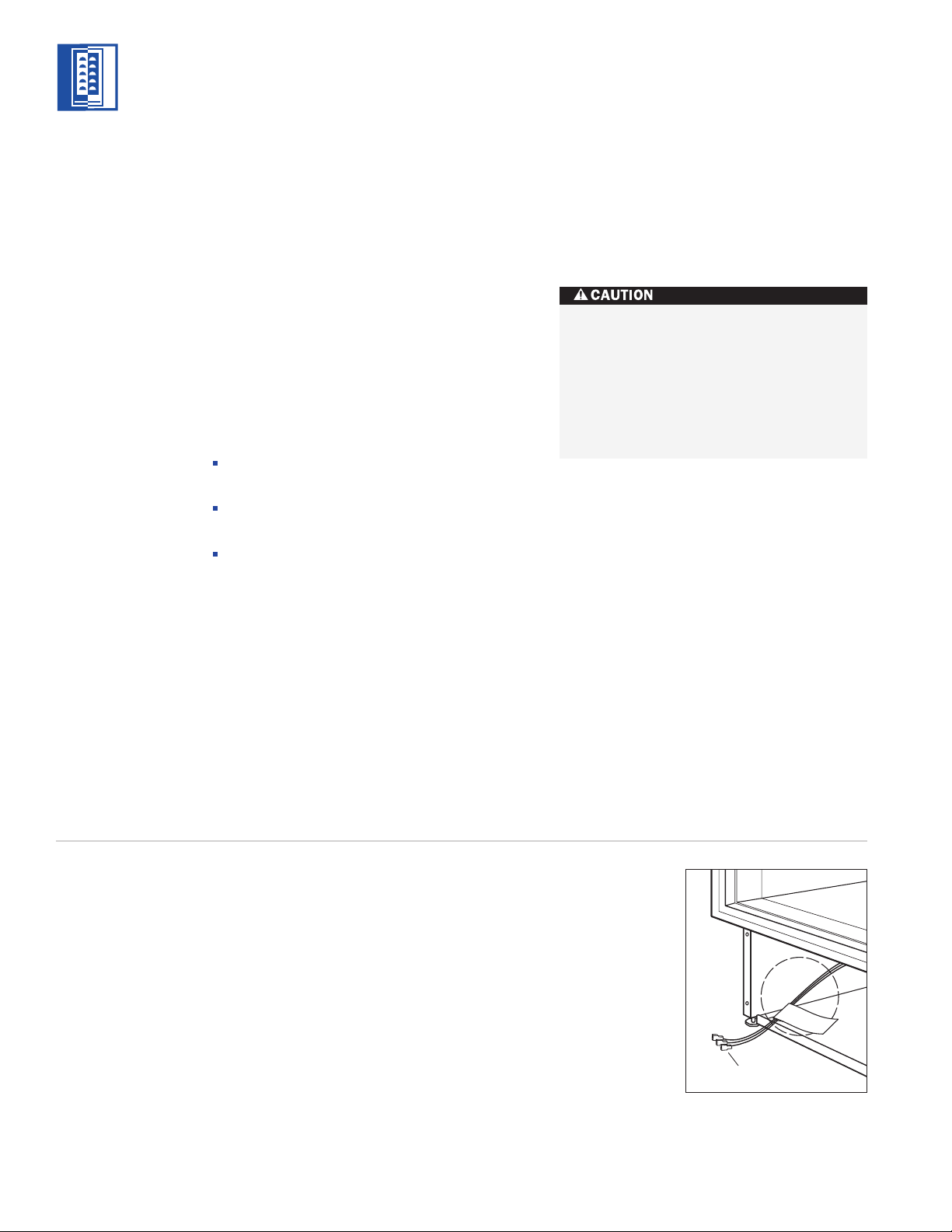
HOME ALARM CONNECTIONS
Before the kickplate and grille are installed, all
necessary wiring connections in the compres-
sor compartment should be completed.
If a home alarm system is to be installed on
the Wine Storage unit, the connections should
be made using the logic supplied with the
alarm specifications. See illustration 6 below
for the appliance lead locations, and refer to
the following for color codes:
Normally open contacts – white with red
stripe wire
Normally closed contacts – white with blue
stripe wire
Common – gray with white stripe wire
Use the 6 mm spade terminals or wire nuts
provided to make the proper wiring connec-
tions.
The alarm circuit in the unit is intended as
a low-voltage, low-current device only. It
should not be used to switch line power.
Any unused terminals should be
completely insulated and all wires should
be secured away from conductive or
moving components.
MODEL
ICB430
29
KICKPLATE AND GRILLE
After the unit has been leveled, make sure the
drain pan is installed properly and install the
kickplate. Refer to illustration 7 below.
IMPORTANT NOTE:
The kickplate must be
removed for servicing. The floor cannot inter-
fere with removal. Refer to label mounted on
the kickplate support for height clearance.
IMPORTANT NOTE:
The floor under the Wine
Storage unit must be at the same level as the
surrounding finished floor to allow for removal
of the unit for servicing.
Replace the grille by reversing the procedure
outlined on page 26. If you’re using a panel
grille, see Overlay Grille Panel on page 31.
Turn power back on to the electrical outlet.
DOOR PANELS
Model ICB430 is offered in two design applica-
tions; stainless steel (/S) and overlay (/O). Each
of these designs is available as a glass door
(G) model.
The stainless steel Model ICB430 is available in
the classic finish only and is shipped from the
factory with the decorative stainless steel door
panel and matching handle in place.
The overlay Model ICB430/O is designed to
accept a decorative door panel to match
surrounding cabinetry. This door panel and the
handle will be provided by the customer.
Before beginning installation, check for the
correct components for the fit and finish
desired. All models require a decorative panel
a minimum of 16 mm thick.
Illus. 7
MODEL ICB430 INSTALLATION INSTRUCTIONS
PANEL
DESIGN
Additional panel
design information
can be found in
the Sub-Zero
Design Guide.
Check our website
at subzero.com.
MODEL
ICB430
30
MODEL ICB430 INSTALLATION INSTRUCTIONS
Glass
Gasket
11 mm
Diameter
6 mm
Diameter
Illus. 8
Illustration 8 shows how this hole passes
through the door frame. The hole center is on
the small locator groove in the front of the
frame. A 6 mm diameter hole is made in the
front wall of the extrusion and a 11 mm
diameter hole through the rest of the frame.
Sub-Zero allows a 6 mm space to slide the
backing material into place on the door frame.
Requirements for proper fit and appearance
are; 16 mm minimum overall thickness, 3 mm
wide groove between backer portion and
overlay portion of panel, finished inside edge
and 11 kg maximum weight. See the Wine
Storage section of the Sub-Zero Design Guide
for additional panel information.
The wine storage unit door is made with
a sealed double wall tempered glass core.
The drill must not contact this core when
drilling. Be sure the hole is centered on
the small groove in the front of the door
frame and the drill passes squarely
through the frame. If you are inexperi-
enced with drilling, fasten the handle from
the rear of the door panel only.
OVERLAY DOOR PANEL
If your customer has chosen an overlay design
door and grille panel, the unit will be shipped
without handle and hardware. The cabinet
manufacturer or designer will provide handle
hardware at the job site to match the overall
decorating scheme. We recommend larger
D-style pulls. The use of small, one-piece
knobs is not recommended.
The metal frame on the glass door has
numerous mounting holes on each side of the
door. This is to accommodate the Sub-Zero
accessory handles and provide for easy attach-
ment of the handle through the door frame.
If you choose not to use these pre-drilled
mounting holes, you must either drill addi-
tional holes through the metal frame of the
door, or attach the handle through the door
panel only.
If you attach through the door panel only, the
handle must be attached before the door panel
is installed and the handle screws will need to
be set into the rear surface of the door panel.
If you choose to drill through the metal door
frame, this must be done before the handle
holes are located and drilled in the panel.
MODEL
ICB430
PANEL
DESIGN
Additional panel
design information
can be found in
the Sub-Zero
Design Guide.
Check our website
at subzero.com.
 Loading...