


Product Specifications Manual
TUP900 Series
Rev. 0.01
Star Micronics Co., Ltd.
Special Products Operating Division

|
|
|
|
Rev 0.01 |
|
--- CONTENTS --- |
|
|
|
||
1. |
GENERAL DESCRIPTION ................................................................................................................... |
|
1-1 |
||
2. |
PRINTER CONFIGURATION............................................................................................................... |
|
2-1 |
||
2-1 Basic Configuration............................................................................................................................... |
|
2-1 |
|||
2-1-1 |
Thermal Mechanism Module ...................................................................................................... |
|
2-1 |
||
2-1-2 |
Presenter Module ....................................................................................................................... |
|
2-1 |
||
2-1-3 |
Control Board Module ................................................................................................................ |
|
2-1 |
||
2-1-4 |
Power Connector Cable Module ................................................................................................ |
|
2-1 |
||
2-1-5 |
Paper Roll Supply Module.......................................................................................................... |
|
2-1 |
||
2-2 Selectable Options for Each Module .................................................................................................... |
|
2-1 |
|||
3. |
BASIC SPECIFICATIONS .................................................................................................................... |
|
3-1 |
||
3-1 Printing Specifications .......................................................................................................................... |
|
3-1 |
|||
3-2 Character Specifications and Bar Code Specifications |
........................................................................3-2 |
||||
3-2-1 |
STAR Line Mode ........................................................................................................................ |
|
3-2 |
||
3-2-2 |
STAR Page Mode ...................................................................................................................... |
|
3-3 |
||
3-3 Paper Specifications ............................................................................................................................. |
|
3-4 |
|||
3-3-1 |
Thermal Paper roll...................................................................................................................... |
|
3-4 |
||
3-3-2 |
Black Mark Specifications .......................................................................................................... |
|
3-7 |
||
3-4 Thermal Mechanism Module ................................................................................................................ |
|
3-9 |
|||
3-4-1 |
Thermal Head............................................................................................................................. |
|
3-9 |
||
3-4-2 |
Auto-cutter.................................................................................................................................. |
|
3-9 |
||
3-4-3 |
Paper Feed Motor ...................................................................................................................... |
|
3-9 |
||
3-4-4 |
Sensors ...................................................................................................................................... |
|
3-9 |
||
3-5 Presenter Module ............................................................................................................................... |
|
3-10 |
|||
3-5-1 |
Feed Rollers............................................................................................................................. |
|
3-10 |
||
3-5-2 |
Paper Feed Motor .................................................................................................................... |
|
3-10 |
||
3-5-3 |
Sensors .................................................................................................................................... |
|
3-10 |
||
3-6 Paper Roll Supply Module .................................................................................................................. |
|
3-11 |
|||
3-6-1 |
Paper Roll Holder ..................................................................................................................... |
|
3-11 |
||
3-6-2 |
Near-end Sensor ...................................................................................................................... |
|
3-11 |
||
3-7 Reliability Specifications ..................................................................................................................... |
|
3-12 |
|||
3-7-1 |
Thermal Mechanism Module .................................................................................................... |
|
3-12 |
||
3-7-2 |
Thermal Head........................................................................................................................... |
|
3-12 |
||
3-7-3 |
Auto-cutter................................................................................................................................ |
|
3-12 |
||
3-7-4 |
Presenter Module ..................................................................................................................... |
|
3-12 |
||
4. |
EXTERNAL SPECIFICATIONS............................................................................................................ |
|
4-1 |
||
4-1 External Specifications ......................................................................................................................... |
|
4-1 |
|||
4-1-1 |
External Dimensions .................................................................................................................. |
|
4-1 |
||
4-1-2 |
External Drawings ...................................................................................................................... |
|
4-1 |
||
4-1-3 |
Mass........................................................................................................................................... |
|
4-1 |
||
4-2 Operation Panel Specifications............................................................................................................. |
|
4-1 |
|||
4-2-1 |
Switches..................................................................................................................................... |
|
4-1 |
||
4-2-2 |
LED ............................................................................................................................................ |
|
4-1 |
||
4-3 Interface................................................................................................................................................ |
|
4-1 |
|||
4-4 DIP Switches ........................................................................................................................................ |
|
4-1 |
|||
5. |
ENVIRONMENT SPECIFICATIONS .................................................................................................... |
|
5-1 |
||
5-1 Temperature and Humidity ................................................................................................................... |
|
5-1 |
|||
5-1-1 |
When Operating ......................................................................................................................... |
|
5-1 |
||
5-1-2 |
When Stored (Excluding Paper roll) ........................................................................................... |
|
5-1 |
||
|
|
|
|
||
TUP900 Series Specifications Manual |
i |
|
|
||

|
|
|
Rev 0.01 |
|
5-2 Static Electricity Tolerance (ESD)......................................................................................................... |
5 |
-2 |
||
5-3 AC Line Noise Tolerance...................................................................................................................... |
5-2 |
|||
5-4 Vibrations, Falling Shocks .................................................................................................................... |
5-2 |
|||
5-4-1 |
Vibration Test (When Packaged) ............................................................................................... |
5-2 |
||
5-4-2 |
Drop Test (When Packaged) ...................................................................................................... |
5-2 |
||
5-5 Dust |
...................................................................................................................................................... |
5-2 |
||
6. |
SAFETY................................................................................................................................................ |
6-1 |
||
6-1 Standard ............................................................................................................................................... |
6-1 |
|||
7. |
USAGE ...........................................................................................EXAMPLE (LAYOUT EXAMPLE) |
7-1 |
||
7-1 Control ............................................................................................................................Board Layout |
7-1 |
|||
7-1-1 .............................................................................................................. |
Control Board Layout 2 |
7-1 |
||
7-1-2 .............................................................................................................. |
Control Board Layout 3 |
7-1 |
||
7-2 High ................................................................Volume Paper Roll Supply (RHU-T900, Optional Part) |
7-1 |
|||
7-2-1 ....................................................................................................................... |
Horizontal Layout |
7-1 |
||
7-2-2 ............................................................................................................................ |
Vertical Layout |
7-1 |
||
8. |
SETTING ......................................................................................................UP THE PRINTER UNIT |
8-1 |
||
8-1 Mounting ................................................................................................................................the Units |
8-1 |
|||
8-1-1 ............................................................................................................ |
Mounting the Printer Unit |
8-1 |
||
8-1-2 ....................................................... |
Mounting the High Volume Paper Roll Supply (RHU - T900) |
8-1 |
||
8-1-3 ....................... |
Mounting the Printer Unit and the High Volume Paper Roll Supply (RHU - T900) |
8-1 |
||
8-2 Mounting .................................................................the High Volume Paper Roll Supply (RHU-T900) |
8-1 |
|||
8-3 Adjusting ......................................................................................................the Paper roll Holder Unit |
8-2 |
|||
8-3-1 ............................................................................................... |
Handling 111 . 5 mm Paper Width |
8-2 |
||
8-3-2 .................................................................................................... |
Handling 82 mm Paper Width |
8-2 |
||
8-3-3 ................................................................................................. |
Handling 79 . 5 mm Paper Width |
8-2 |
||
8-4 Mounting .................................................................................................................the Friction Spring |
8-4 |
|||
8-4-1 ................................................................................................................ |
Using the Spring Base |
8-4 |
||
8-4-2 ............................................................................................... |
When Not Using the Spring Base |
8-4 |
||
8-5 Adjusting ............................................................................................................the Near End Sensor |
8-8 |
|||
8-5-1 ................................................................................................ |
Adjusting to the Paper roll Width |
8-8 |
||
8-5-2 ........................................................................... |
Adjusting to the Paper roll Diameter Direction |
8-8 |
||
9. |
HANDLING .........................................................................................................THE PRINTER UNIT |
9-1 |
||
9-1 Precautions ...........................................................................................................Regarding Designs |
9-1 |
|||
9-2 Precautions ......................................................................................................................for Handling |
9-1 |
|||
9-3 Precautions ............................................................................................................Concerning Safety |
9-2 |
|||
9-4 How ......................................................................................................................to Set the Paper roll |
9-3 |
|||
9-5 Performing .......................................................................................................................Maintenance |
9-7 |
|||
9-5-1 ..................................................................................... |
Cleaning the Thermal Head and Platen |
9-7 |
||
9-5-2 ................................................................................................ |
Handling Recording Paper Jams |
9-7 |
||
9-5-3 ................................................................................................. |
How to Release the Cutter Lock |
9-7 |
||
10. Control ..........................................................................................board module (TBD900 Series) |
10—1 |
|||
11. Power .........................................................................................connector cable module (PBD-9) |
11—2 |
|||
TUP900 Series Specifications Manual |
ii |

Rev 0.01
1. GENERAL DESCRIPTION
The TUP900 series is a direct line thermal printer capable of high speed printing that employs a thermal line dot printing system and is composed of a unit comprising thermal paper roll storage. This type is used, embedded in electronic devices such as games, ATM, and information kiosks.
Model Name Display Directions
T U P 9 9 2 – 2 4 J 1
Installed Fonts |
None: |
Standard models |
|
J1: |
Japanese Characters |
Power Specifications |
24: 24 VDC |
|
Mechanism Type 2: Standard
Printer Type 9: Presenter equipped with a recovery function as standard.
TUP900 Series Thermal Unit Printer
TUP900 Series Specifications Manual |
1-1 |

Rev 0.01
2. PRINTER CONFIGURATION
2-1 Basic Configuration
This unit is composed of modules. The configuration is shown below.
TUP992-24/TUP992-24J1 (Thermal line unit printers)
Thermal mechanism module (TMP900 Series)
Presenter module (PR900 Series)
Control board module (TBD900 Series)
Power connector cable module (PBD-9)
Paper roll supply module
2-1-1 Thermal Mechanism Module
This is composed of the printer mechanism portion that prints using a thermal head while paper is being fed, and an auto-cutter mechanism that cuts the paper by command.
2-1-2 Presenter Module
The presenter module is composed of a mechanism that discharges and that recovers paper (such as receipts) that has been printed and cut by the thermal mechanism module.
2-1-3 Control Board Module
This is the control board that controls the thermal mechanism and the presenter.
2-1-4 Power Connector Cable Module
This is composed of the connector portion that connects the optional power adapter set to the control board, and the power switch.
2-1-5 Paper Roll Supply Module
This supports the thermal paper roll on a shaft and functions to supply paper to the thermal mechanism module. This is also provided a damper roller unit to alleviate the shock caused by the inertia of the paper roll when feeding the thermal paper.
2-2 Selectable Options for Each Module
This unit is used by mounting the following selectable options on each module. The following table shows the options for each module.
Unit/Module Name |
Content of Option |
Part Number |
Part Name |
TUP992-24 |
Power Adapter |
30781430 |
PS60L-24A Adapter Set JP |
TUP992-24J1 |
|
30781440 |
PS60L-24A Adapter Set US |
|
|
30781450 |
PS60L-24A Adapter Set EU |
|
|
30781460 |
PS60L-24A Adapter Set UK |
|
|
30781470 |
PS60L-24A Adapter Set AS |
|
|
30781480 |
PS60L-24A Adapter Set CH |
TMP900 Series |
High Volume Paper Roll |
39590020 |
RHU-T900 |
|
Supply |
|
|
|
Near-end Sensor |
39590030 |
NEU-T900 |
|
Damper Roller |
39591000 |
DRU-T900 |
|
Control Panel Board Unit |
39591500 |
OPA-T900 |
TBD900 Series |
I/F |
39607400 |
IFBD-HD04 |
|
|
39607411 |
IFBD-HC04 |
|
|
39607420 |
IFBD-HU04 |
|
|
39607430 |
IFBD-HN04 |
|
|
39607440 |
IFBD-HE04 |
|
Power Connector Cable |
39206500 |
PBD-9 |
TUP900 Series Specifications Manual |
2-1 |
Rev 0.01
3. |
BASIC SPECIFICATIONS |
||
3-1 |
Printing Specifications |
|
|
|
(1) |
Print Method: |
Direct Thermal Line Printing |
|
(2) |
Dot Configuration: |
832 dots/line |
|
(3) |
Dot Density: |
8 dots/mm (203 DPI) |
|
(4) |
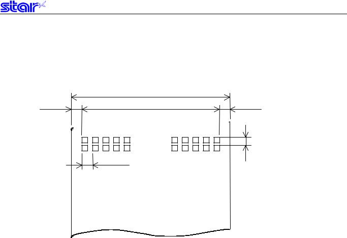
Printing Region: |
Maximum 104 mm (See figure below) |
|
|
|
|
|
|
|
|
|
|
111.5 ±0.5 mm (Maximum paper width) |
|
|
|
|
|
|
|
|||||||||||||||||||||||||||
3.75 mm |
104 mm (Maximum print region, 832 dots) |
|
|
|
|
|
|
|
||||||||||||||||||||||||||||||||||||
|
|
|
|
|
|
|
|
|
|
|
|
|
|
|
|
|
|
|
|
|
|
|
|
|
|
|
|
|
|
|
|
|
|
|
|
|
|
|
|
|
|
|
|
|
|
|
|
|
|
|
|
|
|
|
|
|
|
|
|
|
|
|
|
|
|
|
|
|
|
|
|
|
|
|
|
|
|
|
|
|
|
|
|
|
|
|
|
|
|
|
|
|
|
|
|
|
|
|
|
|
|
|
|
|
|
|
|
|
|
|
|
|
|
|
|
|
|
|
|
|
|
|
|
|
|
|
|
|
|
|
|
|
|
|
|
|
|
|
|
|
|
|
|
|
|
|
|
|
|
|
|
|
|
|
|
|
|
|
|
|
|
|
|
|
|
|
|
|
|
|
|
|
|
|
|
|
|
|
|
|
|
|
|
|
|
|
|
|
|
|
|
|
|
|
|
|
|
|
|
|
|
|
|
|
|
|
|
|
|
|
|
|
|
|
|
|
|
|
|
|
|
|
|
|
0.125 mm
Fig. 3.1.4 Print Region
3.75 mm
0.125 mm
Notes 1) The mechanism can handle paper widths of 79.5 ±0.5 to 111.5 ±0.5 mm. However, it is recommended that a print layout is set that allows plenty of print margin on the left and right sides for the paper that is used. Also, the standard position of printing to the paper width is center of the paper width.
Left and right margins in the printing region are recommended to be a minimum of 3.75 mm.
2)When using a paper width that is less than the maximum print width of the head (104 mm), consider the recording paper feeding state so that the print region does not leave both edges of the recording paper.
(5) |
Print Format: |
Maximum 69 columns (12 × 24 fonts) |
|
|
|
Maximum 34 columns (24 × 24 Chinese character fonts) |
|
|
|
(Only on Chinese character models) |
|
(6) |
Character Space: |
Programmable |
|
(7) |
Print Speed: |
1) HS mode |
Maximum 150 mm/s |
|
|
2) LQ mode |
Maximum 110 mm/s |
|
|
3) HQ mode |
Maximum 60 mm/s |
|
|
4) Two Color Printing Mode |
Maximum 60 mm/s |
|
Note 1) Printing speed varies according to the processing speed of the controller and the temperature |
||
|
control using the head thermistor. |
|
|
(8) |
Paper Feed: |
Thermal Mechanism Module |
Friction Feed Method |
|
|
Presenter Module |
Roller Friction Feed Method |
(9) |
Paper Feed Pitch: |
0.125 mm (1 step on the paper feed pulse motor) |
|
(10) |
Line Width: |
4 mm, 3 mm |
|
(11) |
Cuttable Sheet Length: |
75 to 300 mm |
|
(12) |
Print Head: |
Line Thermal Head |
|
(13) |
Presenter: |
With Recovery Function |
|
(14) |
Emulation: |
Star Line Mode |
|
|
|
Star Page Mode |
|
TUP900 Series Specifications Manual |
3-1 |

Rev 0.01
3-2 Character Specifications and Bar Code Specifications
3-2-1 STAR Line Mode
Item
Character Type
Character
Configuration
Character
Dimensions
Character Code
Table
Bar Codes
Contents
Standard Specifications |
Alphanumeric Characters |
95 Characters |
|
|
Expanded Graphics |
|
128 Characters |
|
International Characters |
32 Characters |
|
Japanese Language |
Alphanumeric Characters |
95 Characters |
|
Chinese Characters |
Expanded Graphics |
|
128 Characters |
|
JIS Level-1 Kanji Set |
(Note |
3489 Characters |
|
1) |
|
|
|
JIS Level-2 Kanji Set |
|
3388 Characters |
|
(Note 1) |
|
|
|
Special Symbols |
|
83 Characters |
|
Single Byte Characters |
282 Characters |
|
Chinese Language |
Alphanumeric Characters |
95 Characters |
|
Character Specifications |
Chinese Characters |
|
7189 Characters |
|
(Note 2) |
|
|
Alphanumeric Characters |
12 × 24 dots (W × H) |
|
|
IBM Graphics |
12 × 32 dots (W × H) |
|
|
Single Byte Characters |
12 × 24 dots (W × H) |
(When using Chinese Specifications) |
|
Two Byte Chinese |
24 × 24 dots (W × H) (When using Chinese Specifications) |
||
Characters |
|
|
|
12 × 24 dots Font |
1.50 mm × 3.00 mm (W × H) |
|
|
12 × 32 dots Font |
1.50 mm × 4.00 mm (W × H) |
|
|
24 × 24 dots Font |
3.00 mm × 3.00 mm (W × H) |
|
|
40 Code Pages |
|
|
|
UPC-A
UPC-E
JAN/EAN8
JAN/EAN13
ITF
CODE39
CODE93
CODE128
CODABAR (NW-7)
Notes 1) JIS level-1 and level-2 kanji sets conform to JISx0208-1983. They correspond to SHIFT-JIS code. 2) Conforms to GB8312
TUP900 Series Specifications Manual |
3-2 |

Rev 0.01
3-2-2 STAR Page Mode
Item
Character Type
Character
Configuration
Character
Dimensions
Character Code
Table
Bar Codes
Contents
Small Characters |
|
|
Alphanumeric Characters |
220 Characters |
|
|
|
and Others |
|
|
|
|
International Characters |
32 Characters |
Standard |
|
|
Alphanumeric Characters |
220 Characters |
Characters |
|
|
and Others |
|
|
|
|
International Characters |
32 Characters |
Chinese Character |
Single Byte |
|
Alphanumeric Characters |
158 Characters |
|
Characters |
|
and Others |
|
|
Japanese |
|
Alphanumeric Characters |
95 Characters |
|
Language |
|
Expanded Graphics |
128 Characters |
|
Chinese |
|
JIS Level-1 Kanji Set (Note |
3489 Characters |
|
Characters |
|
1) |
|
|
|
|
JIS Level-2 Kanji Set |
3388 Characters |
|
|
|
(Note 1) |
|
|
|
|
Special Symbols |
83 Characters |
|
|
|
Single Byte Characters |
282 Characters |
|
Chinese |
|
Alphanumeric Characters |
95 Characters |
|
Characters |
|
Chinese Characters |
7189 Characters |
|
|
|
(Note 2) |
|
Bold Characters |
|
|
Alphanumeric Characters |
128 Characters |
|
|
|
and Others |
|
|
|
|
International Characters |
32 Characters |
OCR Characters |
|
|
Alphanumeric Characters |
103 Characters |
|
|
|
and Others |
|
Small Characters |
8 × 16 dots (W × |
H) |
|
|
Standard |
16 × 24 dots (W × H) |
|
||
Characters |
|
|
|
|
Single Byte |
12 × 24 dots |
(W × H) (When using Chinese Specifications) |
||
Characters |
|
|
|
|
Two Byte Chinese |
24 × 24 dots |
(W × H) (When using Chinese Specifications) |
||
Characters |
|
|
|
|
Bold Characters |
24 × 32 dots (W × H) |
|
||
OCR Characters |
16 × 24 dots (W × H) |
|
||
8 × 16 dots Font |
1.00 mm × 2.00 mm (W × H) |
|
||
12 × 24 dots Font |
1.50 mm × 3.00 mm (W × H) |
|
||
16 × 24 dots Font |
2.00 mm × 3.00 mm (W × H) |
|
||
24 × 24 dots Font |
3.00 mm × 3.00 mm (W × H) |
|
||
24 × 32 dots Font |
3.00 mm × 4.00 mm (W × H) |
|
||
2 Code Pages |
|
|
|
|
UPC-A
UPC-E
JAN/EAN8
JAN/EAN13
ITF
CODE39
CODE93
CODE128
CODABAR (NW-7)
Notes 1) JIS level-1 and level-2 kanji sets conform to JISx0208-1983. They correspond to SHIFT-JIS code. 2) Conforms to GB8312
TUP900 Series Specifications Manual |
3-3 |

Rev 0.01
3-3 |
Paper Specifications |
|
|
3-3-1 |
Thermal Paper roll |
|
|
|
(1) |
Paper Width: |
79.5 ±0.5 mm to 111.5 ±0.5 mm |
|
|
|
(Rolled Dimensions: 80 +0.5/-1 to 112 +0.5/-1 mm) |
|
(2) |
Paper Thickness: |
65 to 150 µm |
|
(3) |
Paper roll Outer Diameter: |
Maximum φ150 mm |
Note 1) Use of optional parts enables up to φ254 mm.
(4) Shaft Core Inner Diameter (mm)/Outer Diameter (mm):
When paper thickness is 65 to 100 µm:
Shaft core inner diameter: Min. 25.4 ±1 mm; Shaft core outer diameter: Min. 31.4 ±1 mm
When paper thickness is 100 to 150 µm:
Shaft core inner diameter: Min. 50.8 ±1 mm; Shaft core outer diameter: Min. 56.8 ±1 mm
Note 1) The tolerance value of the paper roll shaft core (paper tube) varies according to the thickness of the paper that you use.
When using paper that is outside of the above specification ranges, paper jams may occur.
(5) Recommended Thermal Paper
|
Manufacturer |
|
Paper |
|
Manufacturers |
Quality Characteristics and Use |
Thickness |
||
Name |
||||
|
|
(µm) |
||
|
|
|
||
Mitsubishi |
P220AG |
Normal Type |
65 |
|
Paper |
HP220A |
Long-storage Type |
65 |
|
|
HP220AB-1 |
Long-storage Type |
75 |
|
|
P220AB |
Normal Type for Cards and Tickets |
85 |
|
|
P220AC-1 |
Normal Type for Cards and Tickets |
95 |
|
|
P220AC |
Normal Type for Cards and Tickets |
105 |
|
|
P220AD |
Normal Type for Cards and Tickets |
130 |
|
|
P220AE-1 |
Normal Type for Cards and Tickets |
150 |
|
|
PB670 |
2-color Type (Red/Black) |
75 |
|
|
PB770 |
2-color Type (Blue/Black) |
75 |
|
Oji Paper |
PD150R |
Normal Type |
75 |
|
Company |
PD160R |
Long-storage Type |
65/75 |
|
|
PD750R |
2-color Type (Red/Black) |
75 |
|
|
PD700R |
2-color Type (Blue/Black) |
75 |
|
KSP |
P-320RB |
2-color Type (Red/Black) |
65 |
|
|
P-320BB |
2-color Type (Blue/Black) |
65 |
|
Nippon Paper |
TF50KS-E2C |
Normal Type |
65 |
|
Industries |
|
|
|
Note 1) Print density settings must be changed according to the type and thickness of the paper. Density settings can be changed using the print density setting command <ESC> <RS> 'd' n.
(6)Head Adjust Lever on the Thermal Mechanism Module
The TUP900 Series printers require that the head position be adjusted according to the thickness of the paper to be used to ensure high quality printing. The head position is adjusted by changing the position of the head adjustment lever.
See the table below to set to the optimum lever position.
• |
When 65 µm ≤ Paper Thickness < 100 µm: |
Normal Position |
• |
When 100 µm ≤ Paper Thickness ≤ 150 µm: |
Position for Thick Paper |
TUP900 Series Specifications Manual |
3-4 |

Rev 0.01
Head Adjust Lever
Fig. 3.3.1.6.A Normal Position
Head Adjust Lever
Fig. 3.3.1.6.B Position for Thick Paper
TUP900 Series Specifications Manual |
3-6 |
Rev 0.01
(7)Weight Shaft and Loop Guide on the Presenter Module
The TUP900 Series printers require the accessory weight shaft and loop guide for the thickness of the paper to be used to ensure the smooth feeding of paper.
See the table below for the optimum mechanism status.
• When 65 µm ≤ Paper Thickness < 100 µm: |
Loop guide mounting required. |
• When 100 µm ≤ Paper Thickness ≤ 150 µm: |
Weight shaft unnecessary |
Weight shaft mounting required. |
|
|
Loop guide unnecessary |
Note 1) Refer to the PR921-24-A product specifications manual for details regarding the mounting position of the loop guide and the weight shaft and how to mount them.
(8)Pre-printing Range on the Backside of Recording Paper
When pre-printing to the backside of recording paper, it should meet the following specifications.
Printing Direction
|
|
|
|
|
|
|
|
|
|
|
|
|
|
|
|
|
|
25 (mm) |
|
|
|
|
|
|
|
|
|
|
|
|
|
|
|
Paper Back Side |
||||||||||||||||||
|
|
|
|
|
|
|
|
|
|
|
|
|
|
|
|
|
|
|
|
|
|
|
|
|
|
|
|
|
|
|
|
|
|
|
|
|
|
|
|
|
|
|
|
|
|
Pre-printing Prohibited Range |
||||||
|
|
|
|
|
|
|
|
|
|
|
|
|
|
|
|
|
|
|
|
|
10 (mm) |
|
|
|
|
|
|
|
|
|
|
|
|
|
|
|
|
|
|
|
|
|
|
|||||||||
|
|
|
|
|
|
|
|
|
|
|
|
|
|
|
|
|
|
|
|
|
|
|
|
|
|
|
|
|
|
|
|
|
|
|
|
|
|
|
|
|
|
|
||||||||||
|
|
|
|
|
|
|
|
|
|
|
|
|
|
|
|
|
|
|
|
|
|
|
|
|
|
|
|
|
|
|
|
|
|
|
|
|
|
|
|
|
|
|
|
|
|
|
|
|
|
|
|
|
|
|
|
|
|
|
|
|
|
|
|
|
|
|
|
|
|
|
|
|
|
|
|
|
|
|
|
|
|
|
|
|
|
|
|
|
|
|
|
|
|
|
|
|
|
|
|
|
|
|
|
|
|
 Paper Width Center
|
Printing Surface is Paper Back Side |
|
|
|
Min. 15 mm from Paper Edge |
|
|
|
(9) Others |
|
|
|
• Coloring Side: |
Roll outer side |
|
• Trailing Edge Processing: |
Do not glue to fasten to paper roll and shaft core. |
|
|
The trailing edge should not be folded. |
TUP900 Series Specifications Manual |
3-6 |
Rev 0.01
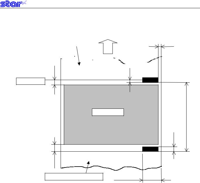
3-3-2 Black Mark Specifications
The following describes the recommended black mark specifications for printers that use the paper out sensor as the black mark sensor.
Printing Direction
|
|
|
|
|
|
|
|
|
|
|
|
|
|
|
|
|
|
|
|
|
|
|
|
|
|
|
|
|
|
|
|
|
|
|
|
|
|
|
|
|
|
|
|
|
|
|
|
|
1+1, -0.8 (mm) |
|
Paper Back Side |
||||||||||||||||||||||||||||||||||||||||||||||||||
|
|
|
|
|
|
|
|
|
|
|
|
|
|
|
|
|
|
|
|
|
|
|
|
|
|
|
|
|
|
|
|
|
|
|
||||||||||||||||
|
|
|
|
|
|
|
|
|
|
|
|
|
|
|
|
|
|
|
|
|
|
|
|
|
|
|
|
|
|
|
|
|
|
|
|
|
|
|
|
|
|
|
|
|
|
|
|
|
|
|
|
|
|
|
|
|
|
|
|
|
|
|
|
|
|
|
|
|
|
|
|
|
|
|
|
|
|
|
|
|
|
|
|
|
|
|
|
|
|
|
|
|
|
|
|
|
|
|
|
|
|
|
|
|
|
|
|
|
|
|
|
|
|
|
|
|
|
|
|
|
|
|
|
|
|
|
|
|
|
|
|
|
|
|
|
|
|
|
|
|
|
|
|
|
|
|
|
|
|
|
|
|
B (mm)
2.5 ±2 (mm)
Cutting Position
Printing Range |
A (mm) |
|
5 ±1 (mm)
C (mm) |
|
Printing Surface is Paper Back Side |
Min. 15 mm |
(1)Black Mark Pitch (Dimension A)
Black mark pitch can be set to a dimension of A = 75 to 300 mm.
Note 1) Black mark pitches can be set to the above describe range, but it is recommended to use a pitch that is at least 80 mm, in consideration of the variation in printing positions.
(2)Black Mark Dimensions
See the following drawings for the dimensions of black marks to be printed.
(3)PCS Value
The PCS value of black marks to be printed should be a minimum of 0.90.
Note 1) The PCS value of black marks can cause page skipping problems or improper page length detection if they do not meet the aforementioned specifications.
For that reason, always ensure that the PCS value is met.
TUP900 Series Specifications Manual |
3-7 |

Rev 0.01
(4)Top Margin (Dimension B)
Set the printing range, leaving plenty of top margin from the cutting position.
When not reversing paper feed, a top margin with a minimum total of 19 mm is recommended with the distance of 15 mm from the thermal head heating elements to the cutting position and the empty paper feed amount (1 line = 4 mm empty feed) considering the motor acceleration step.
If you want a smaller top margin setting, change the memory switch settings. However, in that case, it is recommended to set the top margin of the empty paper feed amount (1 line = 4 mm empty feed) considering the motor acceleration step.
Notes 1) If the top margin is not sufficiently taken, problems, such as the page being skipped, can occur. So, you must set for plenty of top margin.
2)The setting of the printing range should not exceed the black mark pitch.
(5)Bottom Margin (Dimension C)
Set the printing range leaving plenty of bottom margin from the trailing edge of the printing range to the black mark.
It is necessary to consider the printing precision of the black mark, the printing TOP accuracy (±2 mm of the standard printing position), the setup ambient temperature of the printer, and part wear-out to set the bottom margin. It is recommended that the following bottom margin be secured to set the printing range.
Bottom Margin (Dimension C) ≥ 3 mm + (Dimension A × 3%)
Notes 1) If the bottom margin is not sufficiently taken, problems, such as the page being skipped, can occur.
So, you must set for plenty of bottom margin.
2)The setting of the printing range should not exceed the black mark pitch.
(6)Example Setting of the Printing Region
The following shows a printing range setting example when not reverse feeding recording paper.
•When Black Mark Pitch (Dimension A) is 100 mm:
The top margin is set to 20 mm.
The bottom margin is set to 3 mm + (100 mm × 0.03) = 6 mm.
According to the above, it is necessary to set the printing range to less than 100 mm – 20 mm – 6 mm = 74 mm.
Note 1) If you have any questions regarding how to set the printing range for the black mark, consult with STAR Micronics.
TUP900 Series Specifications Manual |
3-8 |

Rev 0.01
3-4 Thermal Mechanism Module |
|
||
3-4-1 Thermal Head |
|
|
|
(1) |
Thermal Element Configuration: |
2 elements/dot |
|
(2) |
Number of Thermal Elements: |
832 dots |
|
(3) |
Thermal Element Scanning Density: |
0.125 mm/dot (8 dots/mm) |
|
(4) |
Average Resistance Value: |
800 Ω ±3% (initial value) |
|
(5) |
Drive Power Voltage: |
Head drive Vh 24 VDC ±10% |
|
|
|
|
Driver IC Vdd 5 VDC ±5% |
3-4-2 Auto-cutter |
|
|
|
(1) |
Cutter Type: |
Separated, V-blade Guillotine Type |
|
(2) |
Paper Cut States: |
Full cut |
|
|
Note 1) The presenter model is standardly equipped with this type of cutter. It does not perform partial |
||
|
cuts. |
|
|
(3) |
Cut Duty: |
1 Cut/within 3 seconds |
|
|
Note 1) The auto-cutter life will notable shorten if it is not used within the above range. |
||
(4) |
Cutter Position: |
The distance from the thermal head heating element positions (the printing position) |
|
|
|
to the auto-cutter blade positions (the cutting position) is 15 ±0.5 mm. |
|
3-4-3 |
Paper Feed Motor |
|
|
|
|
(1) |
Format: |
4 Phase PM Type Bipolar Stepping Motor |
|
|
(2) |
Drive Voltage: |
24 VDC ±10% |
|
3-4-4 |
Sensors |
|
|
|
|
(1) |
Head Temperature Detection: |
Thermistor |
|
|
(2) |
Paper Out Detection: |
Reflective Type Photo-interrupter |
|
|
(3) |
Platen Position Detection: |
Micro Switch |
|
|
(4) |
Cutter Home Position Detection: |
Micro Switch |
|
Note 1) A reflective photo-interrupter is used for the paper out sensor, so it can also be used as a black mark sensor.
In such cases, some restrictions exist for black mark pitch detection.
TUP900 Series Specifications Manual |
3-9 |

Rev 0.01
3-5 |
Presenter Module |
|
|
3-5-1 |
Feed Rollers |
|
|
|
(1) |
Feed Method: |
Friction Method |
|
(2) |
Paper Feed Speed: |
300 mm/s |
|
|
Note 1) Paper feed speed varies according to the ambient environment and the thickness of the paper |
|
|
|
used. |
|
3-5-2 |
Paper Feed Motor |
|
|
|
(1) |
Format: |
DC Brush Motor |
|
(2) |
Drive Voltage: |
24 VDC ±10% |
3-5-3 Sensors
(1)Paper Sensor 1: Reflective Type Photo-interrupter
(2)Paper Sensor 2: Reflective Type Photo-interrupter
(3)Paper Sensor 3: Reflective Type Photo-interrupter
TUP900 Series Specifications Manual |
3-10 |
 Loading...