


3-864-156-31 (1)
Trinitronâ Color
Graphic Display
Operating Instructions |
|
|
GB |
|||
|
|
|
|
|
|
|
Mode d’emploi |
|
|
|
|
|
FR |
|
|
|
|
|||
Bedienungsanleitung |
|
|
|
DE |
||
|
|
|
||||
Manual de instrucciones |
|
ES |
||||
|
|
|
||||
Instruzioni per l’uso |
|
|
|
|
IT |
|
GDM-F400T9
GDM-F500T9
© 1999 by Sony Corporation
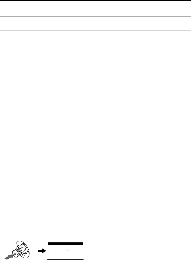
Owner’s Record
The model and serial numbers are located at the rear of the unit. Record these numbers in the spaces provided below. Refer to them whenever you call upon your dealer regarding this product.
Model No. |
|
Serial No. |
WARNING
To prevent fire or shock hazard, do not expose the unit to rain or moisture.
Dangerously high voltages are present inside the unit. Do not open the cabinet. Refer servicing to qualified personnel only.
FCC Notice
This equipment has been tested and found to comply with the limits for a Class B digital device, pursuant to Part 15 of the FCC Rules. These limits are designed to provide reasonable protection against harmful interference in a residential installation. This equipment generates, uses, and can radiate radio frequency energy and, if not installed and used in accordance with the instructions, may cause harmful interference to radio communications. However, there is no guarantee that interference will not occur in a particular installation. If this equipment does cause harmful interference to radio or television reception, which can be determined by turning the equipment off and on, the user is encouraged to try to correct the interference by one or more of the following measures:
–Reorient or relocate the receiving antenna.
–Increase the separation between the equipment and receiver.
–Connect the equipment into an outlet on a circuit different from that to which the receiver is connected.
–Consult the dealer or an experienced radio/TV technician for help. You are cautioned that any changes or modifications not expressly approved in this manual could void your authority to operate this equipment.
EN 55022 Compliance (Czech Republic Only)
This device belongs to category B devices as described in EN 55022, unless it is specifically stated that it is a category A device on the specification label. The following applies to devices in category A of EN 55022 (radius of protection up to 30 meters). The user of the device is obliged to take all steps necessary to remove sources of interference to telecommunication or other devices.
INFORMATION
This product complies with Swedish National Council for Metrology (MPR) standards issued in December 1990 (MPR II) for very low frequency (VLF) and extremely low frequency (ELF).
INFORMATION
Ce produit est conforme aux normes du Swedish National Council for Metrology de décembre 1990 (MPR II) en ce qui concerne les fréquences très basses (VLF) et extrêmement basses (ELF).
Hinweis
Dieses Gerät erfüllt bezüglich tieffrequenter (very low frequency) und tiefstfrequenter (extremely low frequency) Strahlung die Vorschriften des „Swedish National Council for Metrology (MPR)“ vom Dezember 1990 (MPR II).
INFORMACIÓN
Este producto cumple las normas del Consejo Nacional Sueco para Metrología (MPR) emitidas en diciembre de 1990 (MPR II) para frecuencias muy bajas (VLF) y frecuencias extremadamente bajas (ELF).
Dieses Garät entspricht den folgenden europäischen EMVVorschriften für Betrieb in Wohngebieten, gewerblicher Gebleten und Leichtindustriegebieten.
EN55022/1994 Klasse B
EN50082-1/1992
EN61000-3-2/1995
Hinweise
•Aus ergonomischen Gründen wird empfohlen, die Grundfarbe Blau nicht auf dunklem Untergrund zu verwenden (schlechte Erkennbarkeit, Augenbelastung bei zu geringem Zeichenkontrast).
•Aus ergonomischen Gründen (flimmern) sollten nur Darstellungen bei Vertikalfrequenzen ab 70 Hz (ohne Zeilensprung) verwendet werden.
•Die Konvergenz des Bildes kann sich auf Grund des Magnetfeldes am Ort der Aufstellung aus der korrekten Grundeinstellung verändern. Zur Korrektur empfiehlt es sich deshalb, die Regler an der Frontseite für Konvergenz so einzustellen, daß die getrennt sichtbaren Farblinien für Rot, Grün und Blau bei z.B. der Darstellung eines Buchstabens zur Deckung (Konvergenz) gelangen.
Siehe hierzu auch die Erklärungen zu Konvergenz.
NOTICE
This notice is applicable for USA/Canada only.
If shipped to USA/Canada, install only a UL LISTED/CSA LABELLED power supply cord meeting the following specifications:
SPECIFICATIONS Plug Type
Cord
Length
Rating
NOTICE
Cette notice s’applique aux Etats-Unis et au Canada uniquement.
Si cet appareil est export* aux Etats-Unis ou au Canada, utiliser le cordon d’alimentation portant la mention UL LISTED/ CSA LABELLED et remplissant les conditions suivantes: SPECIFICATIONS
Type de fiche |
Fiche Nema 5-15 broches |
Cordon |
Type SVT ou SJT, minimum 3 × 18 AWG |
Longueur |
Maximum 15 pieds |
Tension |
Minimum 7 A, 125 V |
As an ENERGY STAR Partner, Sony Corporation has determined that this product meets the ENERGY STAR guidelines for energy efficiency.
This monitor complies with the
TCO’99 guidelines.
Declaration of Conformity
Trade Name: |
Sony |
Model No.: |
GDM-F400T9, GDM-F500T9 |
Responsible Party: Sony Electronics Inc. |
|
Address: |
1 Sony Drive, Park Ridge, NJ. 07656 USA |
Telephone No.: |
201-930-6970 |
This device complies with Part 15 of the FCC Rules. Operation is subject to the following two conditions: (1) This device may not cause harmful interference, and (2) this device must accept any interference received, including interference that may cause undesired operation.
2
Table of Contents
Precautions. . . . . . . . . . . . . . . . . . . . . . . . . . . . . . . . . . . . . . . . . . . . 4
Identifying parts and controls . . . . . . . . . . . . . . . . . . . . . . . . . . . . . . 5
Setup . . . . . . . . . . . . . . . . . . . . . . . . . . . . . . . . . . . . . . . . . .6
Step 1: Connect your monitor to your computer . . . . . . . . . . . . . . . 6
Step 2: Connect the power cord. . . . . . . . . . . . . . . . . . . . . . . . . . . . 7
Step 3: Turn on the monitor and computer . . . . . . . . . . . . . . . . . . . 7
Connecting Universal Serial Bus (USB) compliant peripherals . . . . 8
Selecting the on-screen menu language (LANG) . . . . . . . . . . . . . . . 8
Selecting the input signal . . . . . . . . . . . . . . . . . . . . . . . . . . . . . . . . . 9
Automatically sizing and centering the picture . . . . . . . . . . . . . . . . . 9
Customizing Your Monitor . . . . . . . . . . . . . . . . . . . . . . .10
Navigating the menu. . . . . . . . . . . . . . . . . . . . . . . . . . . . . . . . . . . . 10
Adjusting the brightness and contrast. . . . . . . . . . . . . . . . . . . . . . . 11
Adjusting the centering of the picture (CENTER) . . . . . . . . . . . . . . 11
Adjusting the size of the picture (SIZE) . . . . . . . . . . . . . . . . . . . . . 11 GB
Adjusting the shape of the picture (GEOM) . . . . . . . . . . . . . . . . . . 12
Enlarging or reducing the picture (ZOOM) . . . . . . . . . . . . . . . . . . . 12
Adjusting the color of the picture (COLOR) . . . . . . . . . . . . . . . . . . 12
Adjusting the quality of the picture (SCREEN) . . . . . . . . . . . . . . . . 13
Additional settings (OPTION) . . . . . . . . . . . . . . . . . . . . . . . . . . . . . 14
Resetting the adjustments . . . . . . . . . . . . . . . . . . . . . . . . . . . . . . . 14
•Trinitron â is a registered trademark of Sony Corporation.
•Macintosh is a trademark licensed to Apple Computer, Inc., registered in the U.S.A. and other countries.
•Windows â and MS-DOS are registered trademarks of Microsoft Corporation in the United States and other countries.
•IBM PC/AT and VGA are registered trademarks of IBM Corporation of the U.S.A.
•VESA and DDC ä are trademarks of the Video Electronics Standard Association.
•ENERGY STAR is a U.S. registered mark.
•All other product names mentioned herein may be the trademarks or registered trademarks of their respective companies.
•Furthermore, “ ä” and “ â” are not mentioned in each case in this manual.
Technical Features . . . . . . . . . . . . . . . . . . . . . . . . . . . . .15
Preset and user modes. . . . . . . . . . . . . . . . . . . . . . . . . . . . . . . . . . 15 Power saving function. . . . . . . . . . . . . . . . . . . . . . . . . . . . . . . . . . . 15
Troubleshooting. . . . . . . . . . . . . . . . . . . . . . . . . . . . . . . .15
If thin lines appear on your screen (damper wires). . . . . . . . . . . . . 15 On-screen messages . . . . . . . . . . . . . . . . . . . . . . . . . . . . . . . . . . . 15 Trouble symptoms and remedies . . . . . . . . . . . . . . . . . . . . . . . . . . 16 Self-diagnosis function . . . . . . . . . . . . . . . . . . . . . . . . . . . . . . . . . . 18
Specifications. . . . . . . . . . . . . . . . . . . . . . . . . . . . . . . . . .18
Appendix. . . . . . . . . . . . . . . . . . . . . . . . . . . . . . . . . . . . . . . i
Preset mode timing table . . . . . . . . . . . . . . . . . . . . . . . . . . . . . . . . . .i TCO’99 Eco-document . . . . . . . . . . . . . . . . . . . . . . . . . . . . . . . . . . . .i
3
Precautions
Warning on power connections
•Use the supplied power cord. If you use a different power cord, be sure that it is compatible with your local power supply.
For the customers in the UK
If you use the monitor in the UK, be sure to use the supplied UK power cable.
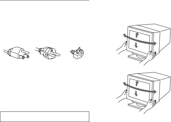
Example of plug types
for 100 to 120 V AC for 200 to 240 V AC for 240 V AC only
•Before disconnecting the power cord, wait at least 30 seconds after turning off the power to allow the static electricity on the screen’s surface to discharge.
•After the power is turned on, the screen is demagnetized (degaussed) for about 3 seconds. This generates a strong magnetic field around the screen which may affect data stored on magnetic tapes and disks placed near the monitor. Be sure to keep magnetic recording equipment, tapes, and disks away from the monitor.
The equipment should be installed near an easily accessible outlet.
Installation
Do not install the monitor in the following places:
•on surfaces (rugs, blankets, etc.) or near materials (curtains, draperies, etc.) that may block the ventilation holes
•near heat sources such as radiators or air ducts, or in a place subject to direct sunlight
•in a place subject to severe temperature changes
•in a place subject to mechanical vibration or shock
•on an unstable surface
•near equipment which generates magnetism, such as a transformer or high voltage power lines
•near or on an electrically charged metal surface
Maintenance
•Clean the screen with a soft cloth. If you use a glass cleaning liquid, do not use any type of cleaner containing an anti-static solution or similar additive as this may scratch the screen’s coating.
•Do not rub, touch, or tap the surface of the screen with sharp or abrasive items such as a ballpoint pen or screwdriver. This type of contact may result in a scratched picture tube.
•Clean the cabinet, panel and controls with a soft cloth lightly moistened with a mild detergent solution. Do not use any type of abrasive pad, scouring powder or solvent, such as alcohol or benzene.
Transportation
When you transport this monitor for repair or shipment, use the original carton and packing materials.
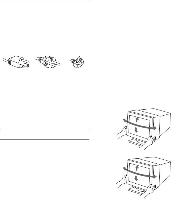
Use of the tilt-swivel
This monitor can be adjusted within the angles shown below. To turn the monitor vertically or horizontally, hold it at the bottom with both hands.
GDM-F400T9
90°
12°
90°
5°
GDM-F500T9
90°
15°
90°
5°
4
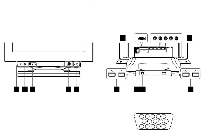
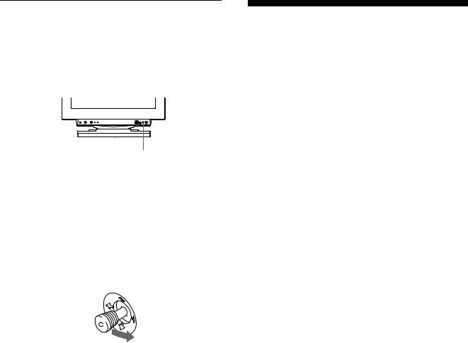
Identifying parts and controls
See the pages in parentheses for further details. GDM-F500T9 is used for illustration purposes throughout this manual.
Front |
Rear |
R |
G |
B |
HD |
VD |
(HD15) |
|
(BNC) |
|
|
RESET |
ASC |
INPUT HD15 BNC |
MENU |
1RESET button (page 14)
This button resets the adjustments to the factory settings.
2ASC (auto sizing and centering) button (page 9)
This button automatically adjusts the size and centering of the picture.
3INPUT button and HD 15/BNC indicators (page 9)
This button selects the HD15 or BNC video input signal. The input signal and corresponding input indicator change each time you press this button.
4Joystick (page 11)
The joystick is used to display the menu and make adjustments to the monitor, including brightness and contrast adjustments.
5 1 (power) switch and indicator (pages 7, 15, 18)
This button turns the monitor on and off. The power indicator lights up in green when the monitor is turned on, and either flashes in green and orange, or lights up in orange when the monitor is in power saving mode.
6AC IN connector (page 7)
This connector provides AC power to the monitor.
7USB (universal serial bus) upstream connector (page 8)
Use this connector to link the monitor to a USB compliant computer.
8USB (universal serial bus) downstream connectors (page 8)
Use these connectors to link USB peripheral devices to the monitor.
9Video input 1 connector (HD15) (page 6)
This connector inputs RGB video signals (0.700 Vp-p, positive) and sync signals.
|
5 |
|
4 |
3 |
2 |
1 |
|
|
|
10 |
9 |
8 |
7 |
6 |
|
GB |
|
|
15 |
14 |
13 12 |
11 |
|
|
||
|
|
|
|
|
|
|
|
|
Pin No. |
Signal |
|
|
|
|
|
|
|
|
|
|
|
|
|
|
|
|
1 |
Red |
|
|
|
|
|
|
|
|
|
|
|
|
|
|
|
|
2 |
Green |
|
|
|
|
|
|
|
|
(Composite Sync on Green) |
|
||||||
|
|
|
|
|
|
|
|
|
3 |
Blue |
|
|
|
|
|
|
|
|
|
|
|
|
|
|
||
4 |
ID (Ground) |
|
|
|
|
|
||
|
|
|
|
|
|
|
||
5 |
DDC Ground* |
|
|
|
|
|
||
|
|
|
|
|
|
|
||
6 |
Red Ground |
|
|
|
|
|
||
|
|
|
|
|
|
|
||
7 |
Green Ground |
|
|
|
|
|
||
|
|
|
|
|
|
|
||
8 |
Blue Ground |
|
|
|
|
|
||
|
|
|
|
|
|
|
|
|
9 |
DDC + 5V* |
|
|
|
|
|
|
|
|
|
|
|
|
|
|
|
|
10 |
Ground |
|
|
|
|
|
|
|
|
|
|
|
|
|
|
||
11 |
ID (Ground) |
|
|
|
|
|
||
|
|
|
|
|||||
12 |
Bi-Directional Data (SDA)* |
|
||||||
|
|
|
|
|
|
|
|
|
13 |
H. Sync |
|
|
|
|
|
|
|
|
|
|
|
|
|
|
|
|
14 |
V. Sync |
|
|
|
|
|
|
|
|
|
|
|
|
|
|||
15 |
Data Clock (SCL)* |
|
|
|
|
|||
|
|
|
|
|
|
|
|
|
* DDC (Display Data Channel) is a standard of VESA.
q; Video input 2 connector (BNC) (page 6)
This connector inputs RGB video signals (0.700 Vp-p, positive) and sync signals.
5
Setup
Before using your monitor, check that the following accessories are included in your carton:
•Power cord (1)
•HD15 video signal cable (1)
•USB cable (1)
•Macintosh adapter (1)
•Windows Monitor Information Disk (1)
•Warranty card (1)
•Notes on cleaning the screen’s surface (1)
•This instruction manual (1)
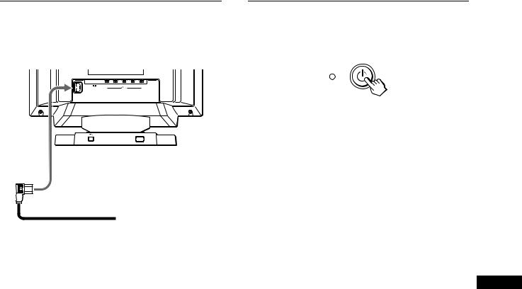
Step 1: Connect your monitor to your computer
Turn off the monitor and computer before connecting.
xConnecting to an IBM PC/AT or compatible computer
R |
G |
B |
HD |
VD |
(HD15) |
|
(BNC) |
|
|
to HD15
to video output
HD15 video signal
 cable (supplied) IBM PC/AT or compatible
computer
If your PC system is not compatible with Plug & Play (DDC2AB or DDC2B+)
This monitor uses the No.9 pin in the video signal connector for Plug & Play (DDC2AB or DDC2B+) compatibility. See page 5 for the location of the No.9 pin.
•If your computer accepts the No.9 pin, use the supplied HD15 video signal cable.
•If your computer does not accept the No.9 pin, please consult your dealer for advice on obtaining an HD15 adapter.
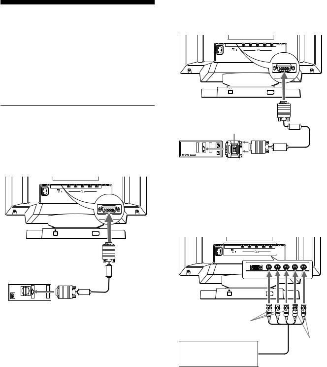
xConnecting to a Macintosh or compatible computer
Use the supplied Macintosh adapter.
(HD15)
to HD15
Macintosh adapter (supplied)*
|
|
HD15 video signal |
Macintosh or |
to video |
cable (supplied) |
compatible computer |
output |
|
*Connect the supplied Macintosh adapter to the computer before connecting the cable. This adapter is compatible with Macintosh LC, Performa, Quadra, Power Macintosh and Power Macintosh G3 series computers. Macintosh II series and some older versions of PowerBook models may need an adapter with micro switches (not supplied).
x Connecting to the five BNC connectors
R |
G |
B |
HD |
VD |
(HD15) |
|
(BNC) |
|
|
to VIDEO IN R/G/B |
|
|
to SYNC IN |
Refer to the preceding |
HD/VD |
|
|
examples to connect to your |
video signal cable |
computer. |
|
|
(SMF-400, not supplied)* |
*Connect the cables from left to right in the following order: Red-Green- Blue-HD-VD.
Notes
•Do not touch the pins of the video cable connector as this might bend the pins.
•Plug & Play (DDC) does not apply to the five BNC connectors. If you want to use Plug & Play, connect your computer to the HD15 connector using the supplied video signal cable.
6
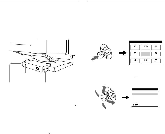
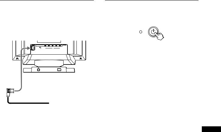
Step 2: Connect the power cord
With the monitor and computer switched off, first connect the power cord to the monitor, then connect it to a power outlet.
R |
G |
B |
HD |
VD |
(HD15) |
|
(BNC) |
|
|
to AC IN
 to a power outlet
power cord (supplied)
Step 3: Turn on the monitor and computer
First turn on the monitor, then turn on the computer.
The installation of your monitor is complete.
If necessary, use the monitor’s controls to adjust the picture.
If no picture appears on your screen
•Check that the monitor is correctly connected to the computer.
•If NO INPUT SIGNAL appears on the screen, try changing the input signal (page 9), and confirm that your computer’s graphic board is completely seated in the correct bus slot.
•If you are replacing an old monitor with this model and OUT OF SCAN RANGE appears on the screen, reconnect the old monitor. Then adjust the computer’s graphic board so that the horizontal frequency is between 30 – 107 kHz (GDM-F400T9) or 30 – 121 kHz (GDM-F500T9), and the vertical frequency is between 48 – 160 Hz.
For more information about the on-screen messages, see “Trouble |
|
symptoms and remedies” on page 16. |
GB |
|
For customers using Windows 95/98
To maximize the potential of your monitor, install the new model information file from the supplied Windows Monitor Information Disk onto your PC.
This monitor complies with the “VESA DDC” Plug & Play standard. If your PC/graphics board complies with DDC, select “Plug & Play Monitor (VESA DDC)” or this monitor’s model name as the monitor type in the “Control Panel” of Windows 95/98. If your PC/graphics board has difficulty communicating with this monitor, load the Windows Monitor Information Disk and select this monitor’s model name as the monitor type.
For customers using Windows NT4.0
Monitor setup in Windows NT4.0 is different from Windows 95/98 and does not involve the selection of monitor type. Refer to the Windows NT4.0 instruction manual for further details on adjusting the resolution, refresh rate, and number of colors.
Adjusting the monitor’s resolution and color number
Adjust the monitor’s resolution and color number by referring to your computer’s instruction manual. The color number may vary according to your computer or video board. The color palette setting and the actual number of colors are as follows:
•High Color (16 bit) t 65,536 colors
•True Color (24 bit) t about 16.77 million colors In true color mode (24 bit), speed may be slower.
7
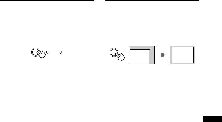
Connecting Universal Serial Bus (USB) compliant peripherals
Your monitor has one upstream and four downstream USB connectors. They provide a fast and easy way to connect USB compliant peripheral devices (such as keyboards, mice, printers and scanners) to your computer using a standardized USB cable. To use your monitor as a hub for your peripheral devices, connect the USBs as illustrated below.
Selecting the on-screen menu language (LANG)
English, French, German, Spanish, Italian, and Japanese versions of the on-screen menus are available. The default setting is English.
1Press the joystick
See page 11 for more information on using the joystick.
MENU |
|
MENU |
COLOR |
CENTER SCREEN |
|
GEOM |
EXIT |
ZOOM |
LANG |
SIZE |
OPTION |
to a USB compliant computer
to USB compliant |
to USB compliant |
peripheral devices |
peripheral devices |
1Turn on the monitor and computer.
2Connect your computer to the square upstream
 connector using the supplied USB cable.
For customers using Windows
If a message appears on your screen, follow the on-screen instructions and select Generic USB Hub as the default setting.
3Connect your USB compliant peripheral devices to the rectangular downstream 
 USB connectors.
Notes
•Not all computers and /or operating systems support USB configurations. Check your computer’s instruction manual to see if you can connect USB devices.
•In most cases, USB driver software needs to be installed on the host computer. Refer to the peripheral device’s instruction manual for further details.
•The monitor functions as a USB hub as long as the monitor is either “on” or in power saving mode.
•If you connect a keyboard or mouse to the USB connectors and then boot your computer for the first time, the peripheral devices may not function. First connect the keyboard and mouse directly to the computer and set up the USB compliant devices. Then connect them to this monitor.
•Do not lean on the monitor when plugging in the USB cables. The monitor may suddenly shift and cause injury.
2Move the joystick to highlight 
 LANG and press the joystick again.
LANGUAGE
 ENGLISH
FRANÇAIS
DEUTSCH
ESPAÑOL
I TALIANO
3Move the joystick up or down to select a language and press the joystick again.
•ENGLISH
•FRANÇAIS: French
•DEUTSCH: German
•ESPAÑOL: Spanish
•ITALIANO: Italian
•
 : Japanese
To close the menu
Press the joystick once to return to the main menu, and twice to return to normal viewing. If no buttons are pressed, the menu closes automatically after about 30 seconds.
To reset to English
Press the RESET button while the LANGUAGE menu is displayed on the screen.
8
Selecting the input signal
You can connect two computers to this monitor using the HD15 and BNC connectors. To switch between the two computers, use the INPUT button.
Press the INPUT button.
The input signal and corresponding input indicator change each time you press this button.
INPUT HD15 BNC
Notes
•If no signal is input to the selected connector, the monitor automatically switches to the other connector.
•If you restart the computer you want to view, or that computer is in power saving mode, the monitor may automatically switch to the other connector’s signal. If this happens, manually select the desired signal using the INPUT button.
Automatically sizing and centering the picture
You can easily adjust the picture to fill the screen by pressing the ASC (auto sizing and centering) button.
Press the ASC button.
The picture automatically fills the screen.
ASC
Notes
• This function is intended for use with a computer running Windows or similar graphic user interface software that provides a full-screen picture. It may not work properly if the background color is dark or if the input picture does not fill the screen to the edges (such as an MSDOS prompt).
• Pictures with an aspect ratio of 5:4 (resolution: 1280 × 1024, 1800 × 1440*) are displayed at their actual resolution and do not fill the screen to the edges.
• The screen may go blank for a few seconds when the ASC button is
pressed. This is not a malfunction.
GB
* GDM-F500T9 only
9
Customizing Your Monitor
You can make numerous adjustments to your monitor using the on-screen menu.
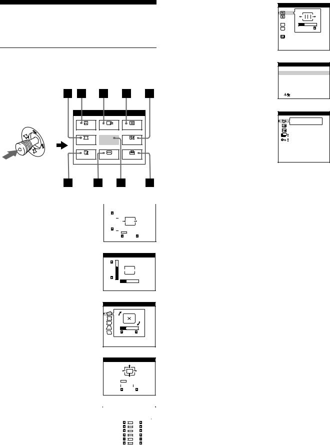
Navigating the menu
Press the joystick to display the main MENU on your screen. See page 11 for more information on using the joystick.
MENU |
|
MENU |
COLOR |
CENTER SCREEN |
|
GEOM |
EXIT |
ZOOM |
LANG |
SIZE |
OPTION |
Use the joystick to select one of the following menus.
1 CENTER (page 11) |
|
|
|
|
|
|
|
|
CENTER |
||||||||
Select the CENTER menu to adjust |
|
|
|
|
|
|
|
|
|
|
|
|
|
|
|
||
the picture’s centering. |
73 |
|
|
|
|
|
|
|
|
|
|
|
|
|
|||
|
|
|
|
|
|
|
|
|
26
2SIZE (page 11)
Select the SIZE menu to adjust the picture’s horizontal and vertical size.
3GEOM (page 12)
Select the GEOM menu to adjust the picture’s rotation and shape.
4ZOOM (page 12)
Select the ZOOM menu to enlarge or reduce the picture.
SIZE
73

 26
26 
GEOMETRY
26
ROTATION
ZOOM
H |
|
|
|
|
|
|
|
|
26 |
|
|
|
|
|
|
|
|
||
V |
|
|
|
|
|
|
|
73 |
|
5 COLOR (page 12) |
|
|
|
|
|
|
|
|
COLOR |
|
|
||||||
Select the COLOR menu to adjust |
|
|
|
|
|
|
||
|
5000K |
6500K |
|
9300K |
|
|||
the picture’s color temperature. You |
|
R BIAS |
|
|
|
50 |
|
|
|
|
|||||||
can use this to match the monitor’s |
|
G BIAS |
|
|
|
50 |
|
|
|
B BIAS |
|
|
50 |
|
|||
colors to a printed picture’s colors. |
|
R GAIN |
|
|
50 |
|
||
|
G GAIN |
|
|
50 |
|
|||
|
|
B GAIN |
|
|
50 |
|
||
|
|
|
|
|
|
|
|
|
|
|
|
|
|
|
|
|
|
6SCREEN (page 13)
Select the SCREEN menu to adjust the picture’s quality. You can adjust the vertical and horizontal convergence, landing, and moire cancellation effect.
7LANG (page 8)
Select LANG to choose the onscreen menu’s language.
8OPTION (page 14)
Select OPTION to adjust the monitor’s options. The options include:
•degaussing the screen
•changing the on-screen menu position
•changing the power saving delay time
•locking the controls
9EXIT
Select EXIT to close the menu.
SCREEN
 TOP
TOP
 BOT
BOT

 26
26  ADJ
ADJ
H CONVERGENCE
LANGUAGE
 ENGLISH
FRANÇAIS
DEUTSCH
ESPAÑOL
I TALIANO
OPTION
ON 
ZZ... 5 SEC
UNLOCK
MANUAL DEGAUSS
10
x Using the joystick
1Select the menu you want to adjust.
Move the joystick up, down, left, or right to highlight the desired menu. Press the joystick to select the menu item.


 b
b
2Adjust the menu.
Move the joystick up, down, left, or right to make the adjustment.
3Close the menu.
Press the joystick once to return to the main menu, and twice to return to normal viewing. If no buttons are pressed, the menu closes automatically after about 30 seconds.
x Resetting the adjustments
Press the RESET button. See page 14 for more information on resetting the adjustments.
RESET
Adjusting the brightness and contrast
Brightness and contrast adjustments are made using a separate BRIGHTNESS/CONTRAST menu.
These settings are stored in memory for all input signals.
1Move the joystick in any direction.
The BRIGHTNESS/CONTRAST menu appears on the screen.
BRIGHTNESS/CONTRAST |
|
26 |
26 |
80.0kHz/ |
75Hz |
the horizontal and vertical frequencies of the current input signal
2Move the joystick up or down to adjust the brightness ( ), and left or right to adjust the contrast (6).
The menu automatically disappears after about 3 seconds.
Adjusting the centering of the |
GB |
picture (CENTER) |
|
This setting is stored in memory for the current input signal.
1Press the joystick.
The main MENU appears on the screen.
2Move the joystick to highlight 
 CENTER and press the joystick again.
The CENTER menu appears on the screen.
3Move the joystick up or down to adjust the vertical centering, and left or right to adjust the horizontal centering.
Adjusting the size of the picture (SIZE)
This setting is stored in memory for the current input signal.
1Press the joystick.
The main MENU appears on the screen.
2Move the joystick to highlight  SIZE and press the joystick again.
The SIZE menu appears on the screen.
3Move the joystick up or down to adjust the vertical size, and left or right to adjust the horizontal size.
11
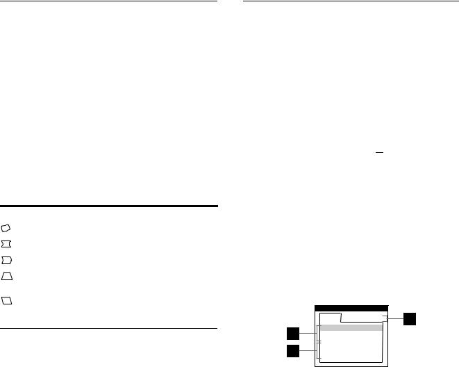
Adjusting the shape of the picture (GEOM)
The GEOM settings allow you to adjust the rotation and shape of the picture.
The rotation setting is stored in memory for all input signals. All other settings are stored in memory for the current input signal.
1Press the joystick.
The main MENU appears on the screen.
2Move the joystick to highlight  GEOM and press the joystick again.
The GEOMETRY menu appears on the screen.
3First move the joystick up or down to select the desired adjustment item. Then move the joystick left or right to make the adjustment.
Select |
To |
|
ROTATION |
rotate the picture |
|
|
|
|
PINCUSHION |
expand or contract the picture sides |
|
|
|
|
PIN BALANCE |
shift the picture sides to the left or right |
|
|
|
|
KEYSTONE |
adjust the picture width at the top of |
|
|
the screen |
|
|
|
|
KEY BALANCE |
shift the picture to the left or right at |
|
the top of the screen |
||
|
||
|
|
Enlarging or reducing the picture (ZOOM)
This setting is stored in memory for the current input signal.
1Press the joystick.
The main MENU appears on the screen.
2Move the joystick to highlight  ZOOM and press the joystick again.
The ZOOM menu appears on the screen.
3Move the joystick left or right to enlarge or reduce the picture.
Note
Adjustment stops when either the horizontal or vertical size reaches its maximum or minimum value.
Adjusting the color of the picture (COLOR)
The COLOR settings allow you to adjust the picture’s color temperature by changing the color level of the white color field. Colors appear reddish if the temperature is low, and bluish if the temperature is high. This adjustment is useful for matching the monitor’s colors to a printed picture’s colors.
This setting is stored in memory for all input signals.
1Press the joystick.
The main MENU appears on the screen.
2Move the joystick to highlight  COLOR and press the joystick again.
The COLOR menu appears on the screen.
3Move the joystick left or right to select a color temperature.
The preset color temperatures are 5000K, 6500K, and 9300K. Since the default setting is 9300K, the whites will change from a bluish hue to a reddish hue as the temperature is lowered to 6500K and 5000K.
4If necessary, fine tune the color temperature.
First move the joystick up or down to select the desired adjustment item. Then move the joystick left or right to make the adjustment.
COLOR
1 |
6500K |
9300K |
R BIAS 

 76
76
G BIAS 

 50
50
B BIAS 

 50
50
R GAIN 

 50
50
G GAIN 

 50
50
B GAIN 

 50
50
1Adjusting the BIAS (black level)
This changes the brightness of both the dark and light areas of an image.
2Adjusting the GAIN (white level)
This changes the contrast of just the light areas of an image.
You can adjust the R(Red), G(Green), and B(Blue) component of the input signal when making changes to items 1 and 2.
If you fine tune the color temperature, the new color settings are stored in memory for each of the three color temperatures and item 3of the on-screen menu changes as follows:
•[5000K] t [1]
•[6500K] t [2]
•[9300K] t [3]
12
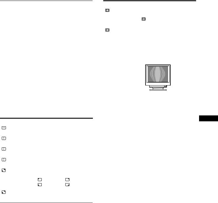
Adjusting the quality of the picture (SCREEN)
The SCREEN settings allow you to adjust the quality of the picture by controlling the convergence, moire, and landing.
•If you see red or blue shadows around letters or lines, adjust the convergence.
•If elliptical or wavy patterns appear on the screen, cancel the moire.
•If the color is irregular at the corners of the screen, adjust the
landing.
The CANCEL MOIRE and MOIRE ADJUST settings are stored in memory for the current input signal. All other settings are stored in memory for all input signals.
1Press the joystick.
The main MENU appears on the screen.
2Move the joystick to highlight  SCREEN and press the joystick again.
The SCREEN menu appears on the screen.
3First move the joystick up or down to select the desired adjustment item. Then move the joystick left or right to make the adjustment.
Select |
To |
|
|||
|
|
|
|
horizontally shift red or blue shadows |
|
|
|
|
|
||
H CONVERGENCE |
|
|
|||
|
|
|
|
|
|
|
|
|
|
vertically shift red or blue shadows |
|
V CONVERGENCE |
|
|
|||
|
|
|
|
|
|
|
|
|
TOP |
vertically shift red or blue shadows at |
|
|
|
|
the top of the screen |
|
|
V CONVER TOP |
|
||||
|
|
|
|
|
|
|
|
|
BOT |
vertically shift red or blue shadows at |
|
|
|
|
|||
V CONVER BOT |
the bottom of the screen |
||||
|
|
|
|
|
|
|
|
|
|
select one of the four corners of the |
|
LANDING |
screen |
|
|||
|
|
|
|
:top left |
:top right |
|
|
|
|
:bottom left |
:bottom right |
|
|
|
|
|
|
|
|
|
ADJ |
reduce any irregularities in the color |
|
|
|
|
of the corner selected in LANDING |
||
LANDING ADJUST |
|||||
to a minimum
Select |
To |
|
turn the moire cancellation function |
CANCEL MOIRE* |
ON or OFF |
|
ADJ (MOIRE ADJUST) appears |
|
in the menu when you select ON |
|
|
ADJ |
adjust the degree of moire |
MOIRE ADJUST |
cancellation until the moire is at a |
|
minimum |
|
|
*Moire is a type of natural interference which produces soft, wavy lines on your screen. It may appear due to interference between the pattern of the picture on the screen and the phosphor pitch pattern of the monitor.
Example of moire
Note
The picture may become fuzzy when CANCEL MOIRE is set to ON.
GB
13

Additional settings (OPTION)
You can manually degauss (demagnetize) the monitor, change the menu position, set the power saving delay time, and lock the controls.
1Press the joystick.
The main MENU appears on the screen.
2Move the joystick to highlight  OPTION and press the joystick again.
The OPTION menu appears on the screen.
3Move the joystick to highlight the desired adjustment item.
Adjust the selected item according to the following instructions.
Degaussing the screen
The monitor is automatically demagnetized when the power is turned on.
To manually degauss the monitor, first move the joystick up or down to select  (MANUAL DEGAUSS). Then move the joystick to the right.
The screen is degaussed for about 3 seconds. If a second degauss cycle is needed, allow a minimum interval of 20 minutes for the best result.
Changing the menu’s position.
Change the menu’s position if it is blocking an image on the screen.
To change the menu’s on-screen position, first move the joystick up or down to select  (OSD H POSITION) for horizontal adjustment, or
  (OSD V POSITION) for vertical adjustment. Then move the joystick to the left or right to shift the on-screen menu.
Changing the power saving delay time.
To adjust the time it takes to enter the power saving
mode, first move the joystick up or down to select  ZZ...
ZZ...
(PWR SAVE DELAY). Then move the joystick to the left or right to select the desired time.
If you select OFF, the monitor does not enter power saving mode. See page 15 for more information about the monitor’s power saving capabilities.
Locking the controls.
To protect adjustment data by locking the controls, first move the joystick up or down to select  (CONTROL LOCK). Then move the joystick to the right to select LOCK.
Only the 1(power) switch, EXIT, and  (CONTROL LOCK) of the
  OPTION menu will operate. If any other items are selected, the
  mark appears on the screen.
To cancel the control lock
Repeat the procedure above and set  (CONTROL LOCK) to UNLOCK.
Resetting the adjustments
This monitor has the following three reset methods. Use the RESET button to reset the adjustments.
RESET
Resetting a single adjustment item
Use the joystick to select the adjustment item you want to reset, and press the RESET button.
Resetting all of the adjustment data for the current input signal
Press the RESET button when no menu is displayed on the screen. Note that the following items are not reset by this method:
•on-screen menu language (page 8)
•on-screen menu position (page 14)
•power saving delay time (page 14)
•control lock (page 14)
Resetting all of the adjustment data for all input signals
Press and hold the reset button for more than two seconds.
Note
The RESET button does not function when  (CONTROL LOCK) is set to LOCK.
14
Technical Features
Preset and user modes
When the monitor receives an input signal, it automatically matches the signal to one of the factory preset modes stored in the monitor’s memory to provide a high quality picture at the center of the screen. (See page i for a list of the factory preset modes.) For input signals that do not match one of the factory preset modes, the digital Multiscan technology of this monitor ensures that a clear picture appears on the screen for any timing in the monitor’s frequency range (horizontal: 30 – 107 kHz (GDM-F400T9) or 30
– 121 kHz (GDM-F500T9), vertical: 48 – 160 Hz) . If the picture is adjusted, the adjustment data is stored as a user mode and automatically recalled whenever the same input signal is received.
Note for Windows users
For Windows users, check your video board manual or the utility program which comes with your graphic board and select the highest available refresh rate to maximize monitor performance.
Power saving function
This monitor meets the power-saving guidelines set by VESA, ENERGY STAR, and NUTEK. If the monitor is connected to a computer or video graphics board that is DPMS (Display Power Management Signaling) compliant, the monitor will automatically reduce power consumption in three stages as shown below.
Power mode |
Power |
1 (power) |
|
|
consumption* |
indicator |
|
|
|
|
|
normal |
≤ 160 |
W (GDM-F500T9) green |
|
operation |
≤ 140 |
W (GDM-F400T9) |
|
|
|
|
|
1 standby |
≤ 100 |
W (GDM-F500T9) green and orange |
|
|
≤ 80 W (GDM-F400T9) |
alternate |
|
|
|
|
|
2 suspend |
≤ 15 W (GDM-F500T9) |
green and orange |
|
|
≤ 10 W (GDM-F400T9) |
alternate |
|
|
|
|
|
3 active off** |
≤ 1 W (GDM-F500T9) |
orange |
|
|
≤ 3 W (GDM-F400T9) |
|
|
|
|
|
|
power off |
0 W |
|
off |
|
|
|
|
*Figures reflect power consumption when no USB compatible peripherals are connected to the monitor.
**When your computer enters the “active off” mode, the input signal is cut and NO INPUT SIGNAL appears on the screen. After the time set in “Changing the power saving delay time.” (page 14) has elapsed, the monitor enters the power saving mode.
To change the power saving delay time
See page 14.
Troubleshooting
Before contacting technical support, refer to this section.
If thin lines appear on your screen (damper wires)
The lines you are experiencing on your screen are normal for the Trinitron monitor and are not a malfunction. These are shadows from the damper wires used to stabilize the aperture grille and are most noticeable when the screen’s background is light (usually white). The aperture grille is the essential element that makes a Trinitron picture tube unique by allowing more light to reach the screen, resulting in a brighter, more detailed picture.
Damper wires
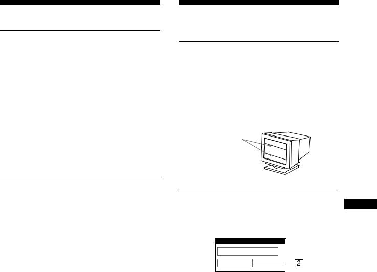
On-screen messages
GB
If there is something wrong with the input signal, one of the following messages appears on the screen. To solve the problem, see “Trouble symptoms and remedies” on page 16.
 INFORMATION
OUT OF SCAN RANGE 

INPUT : HD15
1The input signal condition OUT OF SCAN RANGE
indicates that the input signal is not supported by the monitor’s specifications.
NO INPUT SIGNAL
indicates that no signal is input, or that no signal is input from the selected connector (HD15 or BNC).
2The connector indicator
This message indicates which connector is receiving the wrong signal. If there is something wrong with the signal from both connectors, HD15 and BNC are displayed alternately.
15

Trouble symptoms and remedies
If the problem is caused by the connected computer or other equipment, please refer to the connected equipment’s instruction manual. Use the self-diagnosis function (page 18) if the following recommendations do not resolve the problem.
Symptom |
Check these items |
|
No picture |
|
|
|
If the 1 (power) indicator is not lit |
• Check that the power cord is properly connected. |
|
|
• Check that the 1 (power) switch is in the “on” position. |
|
|
|
|
If the NO INPUT SIGNAL message |
• Check that the video signal cable is properly connected and all plugs are firmly seated in |
|
appears on the screen, or if the 1 |
their sockets. If you are using the five BNC connectors, connect them in the correct order |
|
(power) indicator is either orange or |
(from left to right: Red-Green-Blue-HD-VD) (page 6). |
|
alternating between green and |
• Check that the input select setting is correct (page 9). |
|
orange |
• Check that the HD15 video input connector’s pins are not bent or pushed in. |
|
|
xProblems caused by the connected computer or other equipment |
|
|
• The computer is in power saving mode. Try pressing any key on the computer keyboard. |
|
|
• Check that the computer’s power is “on.” |
|
|
• Check that the graphic board is completely seated in the proper bus slot. |
|
|
|
|
If the OUT OF SCAN RANGE |
xProblems caused by the connected computer or other equipment |
|
message appears on the screen |
• Check that the video frequency range is within that specified for the monitor. If you |
|
|
replaced an old monitor with this monitor, reconnect the old monitor and adjust the |
|
|
frequency range to the following. |
|
|
Horizontal: 30 – 107 kHz (GDM-F400T9), 30 – 121 kHz (GDM-F500T9) |
|
|
Vertical: 48 – 160 Hz |
|
|
|
|
If no message is displayed and the 1 |
• Use the Self-diagnosis function (page 18). |
|
(power) indicator is green or flashing |
|
|
orange |
|
|
|
|
|
If using Windows 95/98 |
• If you replaced an old monitor with this monitor, reconnect the old monitor and do the |
|
|
following. Install the Windows Monitor Information Disk (page 7) and select this monitor |
|
|
(“GDM-F400T9” or “GDM-F500T9”) from among the Sony monitors in the Windows 95/ |
|
|
98 monitor selection screen. If you choose to select “Plug and Play,” connect the monitor |
|
|
to the computer with the HD15 video signal cable. You cannot use the five BNC |
|
|
connectors. |
|
|
|
|
If using a Macintosh system |
• Check that the Macintosh adapter and the video signal cable are properly connected |
|
|
(page 6). |
|
|
|
Picture flickers, bounces, |
• Isolate and eliminate any potential sources of electric or magnetic fields such as other |
|
oscillates, or is scrambled |
monitors, laser printers, electric fans, fluorescent lighting, or televisions. |
|
|
|
• Move the monitor away from power lines or place a magnetic shield near the monitor. |
|
|
• Try plugging the monitor into a different AC outlet, preferably on a different circuit. |
|
|
• Try turning the monitor 90 ° to the left or right. |
xProblems caused by the connected computer or other equipment
•Check your graphics board manual for the proper monitor setting.
•Confirm that the graphics mode (VESA, Macintosh 21" Color, etc.) and the frequency of the input signal are supported by this monitor (page i). Even if the frequency is within the proper range, some video boards may have a sync pulse that is too narrow for the monitor to sync correctly.
•Adjust the computer’s refresh rate (vertical frequency) to obtain the best possible picture.
Picture is fuzzy |
• |
Adjust the brightness and contrast (page 11). |
|
• Degauss the monitor* (page 14). |
|
|
• |
If CANCEL MOIRE is ON, the picture may become fuzzy. Decrease the moire |
|
|
cancellation effect or set CANCEL MOIRE to OFF (page 13). |
|
|
|
16
Symptom |
Check these items |
|
Picture is ghosting |
• |
Eliminate the use of video cable extensions and/or video switch boxes. |
|
• |
Check that all plugs are firmly seated in their sockets. |
Picture is not centered or sized properly
•Press the ASC button (page 9).
•Adjust the size (page 11) or centering (page 11). Note that some video modes do not fill the screen to the edges.
Edges of the image are curved |
• |
Adjust the geometry (page 12). |
|
|
Wavy or elliptical pattern (moire) |
• |
Cancel the moire (page 13). |
|
|
is visible |
xProblems caused by the connected computer or other equipment |
|
||
|
|
|||
|
• Change your desktop pattern. |
|
||
|
|
|
|
|
Color is not uniform |
• |
Degauss the monitor* (page 14). If you place equipment that generates a magnetic field, |
|
|
|
|
such as a speaker, near the monitor, or if you change the direction the monitor faces, color |
|
|
|
|
may lose uniformity. |
|
|
|
• Adjust the landing (page 13). |
|
||
|
|
|
|
|
White does not look white |
• |
Adjust the color temperature (page 12). |
|
|
|
• Check that the five BNC connectors are connected in the correct order (from left to right: |
|
||
|
|
Red-Green-Blue-HD-VD) (page 6). |
|
|
|
|
|
|
|
Letters and lines show red or blue |
• |
Adjust the convergence (page 13). |
|
|
shadows at the edges |
|
|
|
|
|
|
|
|
|
Monitor buttons do not operate |
• |
If the control lock is set to LOCK, set it to UNLOCK (page 14). |
|
|
|
|
|
|
|
USB peripherals do not function |
• |
Check that the appropriate USB connectors are securely connected (page 8). |
|
|
|
• |
Check that the 1 (power) switch is in the “on” position. |
|
|
|
xProblems caused by the connected computer or other equipment |
|
||
|
GB |
|||
|
• |
Check that the power of any self-powered USB compliant peripheral devices is “on.” |
||
|
• Install the latest version of the device driver on your computer. Contact your device’s |
|
||
|
|
manufacturer for information about the appropriate device driver. |
|
|
|
• If your USB compliant keyboard or mouse does not function, connect them directly to |
|
||
|
|
your computer, reboot your computer, and make any necessary adjustments to the USB |
|
|
|
|
settings. Then reconnect the keyboard or mouse to the monitor. |
|
|
|
• For customers using Windows 95 |
|
||
|
|
1. Right-click on My Computer and select Properties. |
|
|
|
|
2. Click on the Device Manager tab. Scroll down and select Universal Serial Bus |
|
|
|
|
Controller. |
|
|
|
|
,If Universal Serial Bus Controller does not appear, you need to load a USB |
|
|
|
|
supplement disk. Contact your computer’s manufacturer for more information about |
|
|
|
|
obtaining a USB supplement disk. |
|
|
|
|
3. Select Generic USB Device from the USB controller list and click on Properties. |
|
|
|
|
4. If there is a check in the box next to “Disable in this hardware profile,” remove the |
|
|
|
|
check. |
|
|
|
|
5. Click on Refresh. |
|
|
|
|
|
|
|
A hum is heard right after the |
• |
This is the sound of the auto-degauss cycle. When the power is turned on, the monitor is |
|
|
power is turned on |
|
automatically degaussed for three seconds. |
|
|
|
|
|
|
|
*If a second degauss cycle is needed, allow a minimum interval of 20 minutes for the best result. A humming noise may be heard, but this is not a malfunction.
Displaying this monitor’s name, serial number, and date of manufacture.
While the monitor is receiving a video signal, press and hold the joystick for more than three seconds to display this monitor’s information box.
Example
 INFORMATION
MODEL : GDM F500T9
SER NO : 1234567
MANUFACTURED : 1998-52
If the problem persists, call your authorized Sony dealer and give the following information.
•Model name: GDM-F400T9, GDM-F500T9
•Serial number
•Name and specifications of your computer and graphics board.
17
Self-diagnosis function
This monitor is equipped with a self-diagnosis function. If there is a problem with your monitor or computer(s), the screen will go blank and the 1 (power) indicator will either light up green or flash orange. If the 1 (power) indicator is lit in orange, the computer is in power saving mode. Try pressing any key on the keyboard.
1 (power) indicator
If the 1 (power) indicator is green
1Remove any plugs from the video input 1 and 2 connectors, or turn off the connected computer(s).
2Press the 1 (power) button to turn the monitor off and on.
3Move the joystick to the right for 2 seconds before the monitor enters power saving mode.
If all four color bars appear (white, red, green, blue), the monitor is working properly. Reconnect the video input cables and check the condition of your computer(s).
If the color bars do not appear, there is a potential monitor failure. Inform your authorized Sony dealer of the monitor’s condition.
If the 1 (power) indicator is flashing orange
Press the 1 (power) button to turn the monitor off and on.
If the 1(power) indicator lights up green, the monitor is working properly.
If the 1 (power) indicator is still flashing, there is a potential monitor failure. Count the number of seconds between orange flashes of the 1 (power) indicator and inform your authorized Sony dealer of the monitor’s condition. Be sure to note the model name and serial number of your monitor. Also note the make and model of your computer and video board.
Specifications
GDM-F400T9
CRT |
0.22 mm aperture grille pitch |
|
19 inches measured diagonally |
|
90-degree deflection |
|
FD Trinitron |
Viewable image size |
Approx. 364.8 × 273.6 mm (w/h) |
|
(14 3/8 × 10 7/8 inches) |
|
18.0" viewing image |
Resolution |
Horizontal: Max. 1600 dots |
|
Vertical: Max. 1200 lines |
Standard image area |
Approx. 352 × 264 mm (w/h) |
|
(13 7/8 × 10 1/2 inches) |
|
or |
|
Approx. 330 × 264 mm (w/h) |
|
(13 × 10 1/2 inches) |
Deflection frequency* |
Horizontal: 30 to 107 kHz |
|
Vertical: 48 to 160 Hz |
AC input voltage/current |
100 to 240 V, 50 – 60 Hz, 1.8 – 1.0 A |
Power consumption |
Max. 140 W (with no USB devices |
|
connected) |
Dimensions |
Approx. 444 × 476 × 455 mm (w/h/d) |
|
(17 1/2 × 18 3/4 × 18 inches) |
Mass |
Approx. 28 kg (61 lb 12 oz) |
Plug and Play |
DDC1/DDC2B/DDC2Bi/DDC2B+ |
Supplied accessories |
See page 6 |
GDM-F500T9
CRT |
0.22 mm aperture grille pitch |
|
21 inches measured diagonally |
|
90-degree deflection |
|
FD Trinitron |
Viewable image size |
Approx. 403.8 × 302.2 mm (w/h) |
|
(16 × 12 inches) |
|
19.8" viewing image |
Resolution |
Horizontal: Max. 1800 dots |
|
Vertical: Max. 1440 lines |
Standard image area |
Approx. 388 × 291 mm (w/h) |
|
(15 3/8 × 11 1/2 inches) |
|
or |
|
Approx. 364 × 291 mm (w/h) |
|
(14 3/8 × 11 1/2 inches) |
Deflection frequency* |
Horizontal: 30 to 121 kHz |
|
Vertical: 48 to 160 Hz |
AC input voltage/current |
100 to 240 V, 50 – 60 Hz, 2.0 – 1.0 A |
Power consumption |
Max. 160 W (with no USB devices |
|
connected) |
Dimensions |
Approx. 502 × 511 × 486.3 mm (w/h/d) |
|
(19 7/8 × 20 1/8 × 19 1/4 inches) |
Mass |
Approx. 34 kg (74 lb 15 oz) |
Plug and Play |
DDC1/DDC2B/DDC2AB/DDC2B+ |
Supplied accessories |
See page 6 |
*Recommended horizontal and vertical timing condition
•Horizontal sync width duty should be more than 4.8% of total horizontal time or 0.8 µs, whichever is larger.
•Horizontal blanking width should be more than 2.5 µsec.
•Vertical blanking width should be more than 450 µsec.
Design and specifications are subject to change without notice.
18
Table des Matières
Précautions. . . . . . . . . . . . . . . . . . . . . . . . . . . . . . . . . . . . . . . . . . . . 4
Identification des composants et des commandes . . . . . . . . . . . . . . 5
Installation . . . . . . . . . . . . . . . . . . . . . . . . . . . . . . . . . . . . .6
1re étape:Raccordez le moniteur à l’ordinateur . . . . . . . . . . . . . . . 6 2e étape:Branchez le cordon d’alimentation . . . . . . . . . . . . . . . . . . 7 3e étape:Mettez le moniteur et l’ordinateur sous tension . . . . . . . . 7 Raccordement de périphériques compatibles USB
(Universal Serial Bus) . . . . . . . . . . . . . . . . . . . . . . . . . . . . . . . . . . . . 8 Sélection de la langue d’affichage des menus (LANG) . . . . . . . . . . 8 Sélection du signal d’entrée . . . . . . . . . . . . . . . . . . . . . . . . . . . . . . . 9 Réglage automatique de la taille et du centrage de l’image . . . . . . . 9
•Trinitron â est une marque commerciale déposée de Sony Corporation.
•Macintosh est une marque commerciale sous licence d’Apple Computer, Inc., déposée aux Etats-Unis et dans d’autres pays.
•Windowsâ et MS-DOS sont des marques déposées de Microsoft Corporation aux Etats-Unis et dans d’autres pays.
•IBM PC/AT et VGA sont des marques commerciales déposées d’IBM Corporation aux Etats-Unis.
•VESA et DDC ä sont des marques commerciales de Video Electronics Standard Association.
•ENERGYSTARestunemarquedéposée aux Etats-Unis.
•Tous les autres noms de produits mentionnés dans le présent mode d’emploi peuvent être des marques commerciales ou des marques commerciales déposées de leurs sociétés respectives.
•Les symboles “ ä” et “ â” ne sont pas mentionnés systématiquement dans le présent mode d’emploi.
Personnalisation de votre moniteur. . . . . . . . . . . . . . . .10
Pilotage par menus. . . . . . . . . . . . . . . . . . . . . . . . . . . . . . . . . . . . . 10 Réglage de la luminosité et du contraste . . . . . . . . . . . . . . . . . . . . 11 Réglage du centrage de l’image (CENTRE). . . . . . . . . . . . . . . . . . 11 Réglage de la taille de l’image (TAILLE) . . . . . . . . . . . . . . . . . . . . 11 Réglage de la forme de l’image (GEOM) . . . . . . . . . . . . . . . . . . . . 12 FR Agrandir ou réduire l’image (ZOOM) . . . . . . . . . . . . . . . . . . . . . . . 12 Réglage des couleurs de l’image (COUL.) . . . . . . . . . . . . . . . . . . . 12 Réglage de la qualité de l’image (ECRAN). . . . . . . . . . . . . . . . . . . 13 Réglages supplémentaires (OPTION) . . . . . . . . . . . . . . . . . . . . . . 14 Réinitialisation des réglages . . . . . . . . . . . . . . . . . . . . . . . . . . . . . . 14
Caractéristiques techniques. . . . . . . . . . . . . . . . . . . . . .15
Modes présélectionné et utilisateur . . . . . . . . . . . . . . . . . . . . . . . . 15 Fonction d’économie d’énergie. . . . . . . . . . . . . . . . . . . . . . . . . . . . 15
Dépannage . . . . . . . . . . . . . . . . . . . . . . . . . . . . . . . . . . . .15
Si de fines lignes apparaissent à l’écran (fils d’amortissement) . . . 15 Messages affichés à l’écran . . . . . . . . . . . . . . . . . . . . . . . . . . . . . . 15 Symptômes et remèdes . . . . . . . . . . . . . . . . . . . . . . . . . . . . . . . . . 16 Fonction d’autodiagnostic . . . . . . . . . . . . . . . . . . . . . . . . . . . . . . . . 18
Spécifications. . . . . . . . . . . . . . . . . . . . . . . . . . . . . . . . . .18
Appendix. . . . . . . . . . . . . . . . . . . . . . . . . . . . . . . . . . . . . . . i
Preset mode timing table . . . . . . . . . . . . . . . . . . . . . . . . . . . . . . . . . .i TCO’99 Eco-document . . . . . . . . . . . . . . . . . . . . . . . . . . . . . . . . . . . .i
3
Précautions
Avertissement sur le raccordement à la source d’alimentation
•Utilisez le cordon d’alimentation fourni. Si vous utilisez un cordon d’alimentation différent, assurez-vous qu’il est compatible avec votre tension d’alimentation secteur locale.
Pour les clients au Royaume-Uni
Si vous utilisez ce moniteur au Royaume-Uni, utilisez le cordon d’alimentation fourni au Royaume-Uni.
Exemple de types de fiches
pour 100 à 120 V CA pour 200 à 240 V CA pour 240 V CA uniquement
•Avant de débrancher le cordon d’alimentation, attendez au moins 30 secondes après avoir actionné le commutateur d’alimentation de manière à permettre la décharge de l’électricité statique à la surface de l’écran.
•Après que le courant a été branché, l’écran est démagnétisé pendant environ 3 secondes. Cela génère un puissant champ magnétique autour de l’encadrement métallique qui peut affecter les données mémorisées sur une bande magnétique ou des disquettes situées à proximité. Placez ces systèmes d’enregistrement magnétique et ces bandes, et disquettes à l’écart du moniteur.
L’appareil doit être installé à proximité d’une prise murale aisément accessible.
Installation
N’installez pas le moniteur dans les endroits suivants:
•sur des surfaces molles (moquette, nappe, etc.) ou à proximité de tissus (rideaux, tentures, etc.) qui risquent d’obstruer les orifices de ventilation;
•à proximité de sources de chaleur comme des radiateurs ou des conduits d’air, ni dans un endroit directement exposé au rayonnement solaire;
•sujet à de fortes variations de température;
•soumis à des vibrations ou à des chocs mécaniques;
•sur une surface instable;
•à proximité d’appareils générant un champ magnétique comme un transformateur ou des lignes à haute tension;
•à proximité ou sur une surface métallique chargée électriquement.
Entretien
•Nettoyez l’écran à l’aide d’un chiffon doux. Si vous utilisez un produit nettoyant pour vitres, n’utilisez aucun type de produit contenant une solution antistatique ou des additifs similaires parce que vous risquez sinon de rayer le revêtement de l’écran.
•Ne frottez pas, ne touchez pas et ne tapotez pas la surface de l’écran avec des objets abrasifs ou aux arêtes vives comme un stylo à bille ou un tournevis. Ce type de contact risque en effet de rayer le tube image.
•Nettoyez le châssis, le panneau et les commandes à l’aide d’un chiffon doux légèrement imprégné d’une solution détergente neutre. N’utilisez jamais de tampons abrasifs, de poudre à récurer ou de solvants tels que de l’alcool ou de la benzine.
Transport
Pour transporter ce moniteur en vue de réparations ou de son expédition, utilisez le carton d’emballage et les matériaux de conditionnement d’origine.
Utilisation du support pivotant
Ce moniteur peut être réglé suivant les angles précisés ci-dessous. Pour faire pivoter le moniteur verticalement et horizontalement, maintenez-le des deux mains par la base comme illustré cidessous.
GDM-F400T9
90°
12°
90°
5°
GDM-F500T9
90°
15°
90°
5°
4
Identification des composants et des commandes
Pour plus de détails, reportez-vous au pages indiquées entre parenthèses. C’est le GDM-F500T9 qui est représenté dans les illustrations figurant dans le présent mode d’emploi.
Avant |
Arrière |
R |
G |
B |
HD |
VD |
(HD15) |
|
(BNC) |
|
|
RESET |
ASC |
INPUT HD15 BNC |
MENU |
1Touche RESET (réinitialisation) (page 14)
Cette touche réinitialise les réglages aux valeurs par défaut.
2Touche ASC (taille & centrage automatiques) (page 9)
Cette touche ajuste automatiquement la taille et le centrage des images.
3Touche INPUT (entrée) et indicateurs HD15/BNC (page 9)
Cette touche sélectionne le signal d’entrée vidéo HD15 ou BNC. Le signal d’entrée et l’indicateur d’entrée correspondant changent chaque fois que vous appuyez sur cette touche.
4Manette de commande (page 11)
La manette de commande sert à afficher le menu et à ajuster les paramètres de réglage du moniteur, y compris la luminosité et le contraste.
5Commutateur et indicateur 1 (alimentation)
(pages 7, 15, 18)
Cette touche met le moniteur sous et hors tension. L’indicateur d’alimentation s’allume en vert lorsque le moniteur est sous tension et clignote en vert et en orange ou s’allume en orange lorsque le moniteur se trouve en mode d’économie d’énergie.
6Connecteur AC IN (page 7)
Ce connecteur assure l’alimentation du moniteur.
7Connecteur d’amont USB (bus sériel universel) (page 8)
Utilisez ce connecteur pour relier le moniteur à un ordinateur compatible USB.
8Connecteurs d’aval USB (bus sériel universel) (page 8)
Utilisez ces connecteurs pour relier des appareils périphériques USB au moniteur.
9Connecteur d’entrée vidéo 1 (HD15) (page 6)
Ce connecteur assure l’entrée des signaux vidéo RVB (0,700 Vp-p, positifs) et des signaux de synchronisation.
|
5 |
4 |
3 |
2 |
1 |
|
|
|
10 |
9 |
8 |
7 |
6 |
|
|
|
FR |
||||||
|
15 14 13 12 |
11 |
|
||||
|
|
||||||
|
|
|
|
|
|
|
|
Broche nº |
Signal |
|
|
|
|
|
|
|
|
|
|
|
|
|
|
1 |
Rouge |
|
|
|
|
|
|
|
|
|
|
|
|
|
|
2 |
Vert |
|
|
|
|
|
|
|
(Synchro composite sur le vert) |
|
|||||
|
|
|
|
|
|
|
|
3 |
Bleu |
|
|
|
|
|
|
|
|
|
|
|
|
|
|
4 |
ID (masse) |
|
|
|
|
|
|
|
|
|
|
|
|
|
|
5 |
Masse DDC* |
|
|
|
|
|
|
|
|
|
|
|
|
|
|
6 |
Masse rouge |
|
|
|
|
|
|
|
|
|
|
|
|
|
|
7 |
Masse vert |
|
|
|
|
|
|
|
|
|
|
|
|
|
|
8 |
Masse bleu |
|
|
|
|
|
|
|
|
|
|
|
|
|
|
9 |
DDC + 5V* |
|
|
|
|
|
|
|
|
|
|
|
|
|
|
10 |
Masse |
|
|
|
|
|
|
|
|
|
|
|
|
|
|
11 |
ID (masse) |
|
|
|
|
|
|
|
|
|
|
||||
12 |
Données bidirectionnelles (SDA)* |
|
|||||
|
|
|
|
|
|
|
|
13 |
Synchro H |
|
|
|
|
|
|
|
|
|
|
|
|
|
|
14 |
Synchro V |
|
|
|
|
|
|
|
|
|
|
||||
15 |
Données d’horloge (SCL)* |
|
|||||
|
|
|
|
|
|
|
|
* DDC (Display Data Channel) est une norme de VESA.
q; Connecteur d’entrée vidéo 2 (BNC) (page 6)
Ce connecteur assure l’entrée des signaux vidéo RVB (0,700 Vp-p, positifs) et des signaux de synchronisation.
5

Installation
Avant de mettre ce moniteur en service, vérifiez si tous les accessoires suivants se trouvent bien dans le carton:
•Cordon d’alimentation (1)
•Câble de signal vidéo HD15 (1)
•Câble USB (1)
•Adaptateur Macintosh (1)
•Windows Monitor Information Disk (1)
•Carte de garantie (1)
•Remarques sur l’entretien de la surface de l’écran (1)
•Ce mode d’emploi (1)
1re étape: Raccordez le moniteur à l’ordinateur
Mettez le moniteur et l’ordinateur hors tension avant de procéder au raccordement.
xRaccordement à un PC/AT IBM ou à un ordinateur compatible
R |
G |
B |
HD |
VD |
(HD15) |
|
(BNC) |
|
|
vers HD15
vers la sortie vidéo
Câble de signal vidéo
 HD15 (fourni) PC/AT IBM ou ordinateur
compatible
Si votre système PC n’est pas compatible Plug & Play (DDC2AB ou DDC2B+)
Ce moniteur utilise la broche nº 9 du connecteur de signal vidéo pour la compatibilité Plug & Play (DDC2AB ou DDC2B+). Voir page 5 pour l’emplacement de la broche nº 9.
•Si votre ordinateur accepte la broche nº 9, utilisez le câble de signal vidéo HD15 fourni.
•Si votre ordinateur n’accepte pas la broche nº 9, consultez votre revendeur de manière à vous procurer un adaptateur HD15.
xRaccordement à un ordinateur Macintosh ou compatible
Utilisez l’adaptateur Macintosh fourni.
(HD15)
vers HD15
Adaptateur Macintosh (fourni)*
|
Câble de signal vidéo |
Macintosh ou |
vers la sortie vidéo HD15 (fourni) |
ordinateur |
|
compatible |
|
*Raccordez l’adaptateur Macintosh fourni à l’ordinateur avant de raccorder le câble. Cet adaptateur est compatible avec les ordinateurs Macintosh LC, Performa, Quadra, Power Macintosh et Power Macintosh G3. Les ordinateurs Macintosh II ainsi que certaines anciennes versions de PowerBook peuvent nécessiter un adaptateur doté de microcommutateurs (non fourni).
x Raccordement aux cinq connecteurs BNC
R |
G |
B |
HD |
VD |
(HD15) |
|
(BNC) |
|
|
vers VIDEO IN R/G/B |
|
|
Voyez les exemples |
vers SYNC IN |
|
HD/VD |
||
précédents pour le |
|
|
raccordement à votre |
Câble de signal vidéo |
|
ordinateur. |
||
(SMF-400, non fourni)* |
||
|
*Raccordez les câbles de gauche à droite dans l’ordre suivant : Rouge- Vert-Bleu-HD-VD.
Remarques
•Ne touchez pas les broches du connecteur de câble vidéo, parce que vous risquez sinon de les fausser.
•La norme Plug & Play (DDC) ne s’applique pas aux cinq connecteurs BNC. Si vous utilisez la norme Plug & Play, raccordez le connecteur HD15 à l’ordinateur à l’aide du câble de signal vidéo fourni.
6
2e étape: Branchez le cordon d’alimentation
Le moniteur et l’ordinateur étant hors tension, branchez d’abord le cordon d’alimentation sur le moniteur et ensuite sur une prise murale.
R |
G |
B |
HD |
VD |
(HD15) |
|
(BNC) |
|
|
vers AC IN
 vers une prise murale cordon d’alimentation (fourni)
3e étape: Mettez le moniteur et l’ordinateur sous tension
Mettez d’abord le moniteur sous tension et puis l’ordinateur.
L’installation de votre moniteur est à présent terminée.
Si nécessaire, utilisez les commandes du moniteur pour régler l’image.
Si aucune image n’apparaît à l’écran
•Vérifiez si le moniteur est correctement raccordé à l’ordinateur.
•Si l’indication PAS ENTREE VIDEO apparaît à l’écran, changez le signal d’entrée (page 9), et vérifiez si la carte graphique de votre ordinateur est complètement introduite dans la fente de bus appropriée.
•Si vous remplacez un ancien moniteur par ce modèle et si l’indication HORS PLAGE DE BALAYAGE apparaît à l’écran, rebranchez l’ancien moniteur. Ajustez ensuite la carte graphique de l’ordinateur de façon à ce que la fréquence horizontale soit comprise entre 30 et 107 kHz (GDM-F400T9) ou entre 30 et 121 kHz (GDM-F500T9), et la fréquence verticale entre 48 et 160 Hz.
Pour plus d’informations sur les messages affichés à l’écran, |
FR |
reportez-vous à la section “Symptômes et remèdes” à la page 16. |
Pour les clients utilisant Windows 95/98
Pour maximaliser le potentiel de votre moniteur, installez sur votre ordinateur le nouveau fichier d’informations modèle depuis la disquette “Windows Monitor Information Disk”.
Ce moniteur est conforme à la norme Plug & Play “VESA DDC”. Si votre PC/carte graphique est conforme à la norme DDC, sélectionnez “Plug & Play Monitor (VESA DDC)” ou la désignation de ce moniteur comme type de moniteur dans le “Control Panel” sous Windows 95/98. Si votre PC/carte graphique a des difficultés à communiquer avec ce moniteur, chargez la disquette “Windows Monitor Information Disk” et sélectionnez la désignation de ce moniteur comme type de moniteur.
Pour les clients utilisant Windows NT4.0
L’installation du moniteur sous Windows NT4.0 est différente de Windows 95/98 et n’implique pas la sélection du type de moniteur. Reportez-vous au mode d’emploi Windows NT4.0 pour plus de détails sur le réglage de la résolution, le taux de régénération et le nombre de couleurs.
Réglage de la résolution du moniteur et du nombre de couleurs
Ajustez la résolution du moniteur et le nombre de couleurs en vous référant au mode d’emploi de votre ordinateur. Le nombre de couleurs peut varier selon votre ordinateur ou votre carte vidéo. Le réglage de la palette de couleurs et le nombre réel de couleurs se présentent comme suit:
•High Color (16 bit) t 65.536 couleurs
•True Color (24 bit) t environ 16,77 millions de couleurs En mode True Color (24 bit), la vitesse peut être inférieure.
7
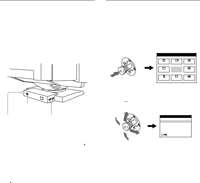
Raccordement de périphériques compatibles USB (Universal Serial Bus)
Votre moniteur est doté d’un connecteur USB d’amont et de quatre connecteurs USB d’aval. Ces connecteurs offrent un moyen simple et rapide de raccorder des périphériques compatibles USB (comme des claviers, une souris, des imprimantes et des scanners) à votre ordinateur au moyen d’un câble USB standardisé.
Pour pouvoir utiliser votre moniteur comme une plate-forme pour vos périphériques, raccordez les USB comme illustré ci-dessous.
Sélection de la langue d’affichage des menus (LANG)
Les écrans de menu peuvent être affichés en français, anglais, allemand, espagnol, italien et japonais. La sélection par défaut est l’anglais.
1Appuyez sur la manette de commande.
Voir page 11 pour plus d’informations sur l’utilisation de la manette de commande.
MENU |
|
MENU |
COUL. |
CENTRE |
ECRAN |
GEOM |
QUITTE |
ZOOM |
LANG |
TAILLE |
OPTION |
vers un ordinateur compatible USB
vers les |
vers les |
périphériques |
périphériques |
compatibles USB |
compatibles USB |
1Mettez le moniteur et l’ordinateur sous tension.
2Raccordez votre ordinateur au connecteur 
 d’amont rectangulaire au moyen du câble USB fourni.
Pour les clients utilisant Windows
Si un message apparaît à l’écran, suivez les instructions affichées et sélectionnez Generic USB Hub comme réglage par défaut.
3Raccordez vos périphériques aux connecteurs USB 
 d’aval rectangulaires.
Remarques
•Tous les ordinateurs et/ou systèmes d’exploitation supportent les configurations USB. Vérifiez dans le mode d’emploi de votre ordinateur si vous pouvez raccorder des systèmes USB.
•Dans la plupart des cas, le logiciel de pilotage USB doit être installé sur l’ordinateur hôte. Pour plus de détails, reportez-vous au mode d’emploi du périphérique.
•Le moniteur fonctionne comme une plate-forme USB tant que le moniteur est sous tension (“on”) ou en mode d’économie d’énergie.
•Si vous raccordez un clavier ou une souris aux connecteurs USB et si vous démarrez ensuite votre ordinateur pour la première fois, il se peut que les périphériques ne fonctionnent pas. Raccordez d’abord le clavier et la souris directement à l’ordinateur et installez les appareils compatibles USB. Raccordez-les ensuite à ce moniteur.
•Ne vous appuyez pas sur le moniteur lorsque vous branchez les câbles USB. Le moniteur risque de pivoter et de vous blesser.
2Déplacez la manette de commande de façon à
mettre 
 LANG en évidence et appuyez à nouveau sur la manette de commande.
LANGUAGE
 ENGLISH
FRANÇAIS
DEUTSCH
ESPAÑOL
I TALIANO
3Déplacez la manette de commande vers le haut ou le bas pour sélectionner une langue et appuyez à nouveau sur la manette de commande.
•ENGLISH: anglais
•FRANÇAIS
•DEUTSCH: allemand
•ESPAÑOL: espagnol
•ITALIANO: italien
•
 : japonais
Pour quitter le menu
Appuyez une fois sur la manette de commande pour revenir au menu principal et deux fois pour revenir à la visualisation normale. Si vous n’actionnez aucune touche, le menu se referme automatiquement au bout de 30 secondes.
Pour restaurer l’anglais
Appuyez sur la touche RESET pendant que le menu LANGUAGE est affiché à l’écran.
8
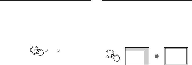
Sélection du signal d’entrée
Vous pouvez raccorder deux ordinateurs à ce moniteur au moyen des connecteurs HD15 et BNC. Pour commuter les deux ordinateurs, utilisez la touche INPUT.
Appuyez sur la touche INPUT.
Chaque fois que vous appuyez sur la touche INPUT, le signal d’entrée et l’indicateur correspondant alternent.
Réglage automatique de la taille et du centrage de l’image
Vous pouvez ajuster aisément l’image de façon à ce qu’elle s’adapte à l’écran en appuyant sur la touche ASC (taille & centrage automatiques).
Appuyez sur la touche ASC.
L’image est ajustée automatiquement pour s’adapter à l’écran.
INPUT HD15 BNC
Remarques
•Si aucun signal n’est entré via le connecteur sélectionné, le moniteur commute automatiquement le signal de l’autre connecteur.
•Si vous redémarrez l’ordinateur que vous voulez utiliser ou si cet ordinateur se trouve en mode d’économie d’énergie, il se peut que le moniteur sélectionne automatiquement le signal de l’autre connecteur. Si cela se produit, sélectionnez manuellement le signal voulu à l’aide de la touche INPUT.
ASC
Remarques
•Cette fonction est destinée à être utilisée sur des ordinateurs tournant sous Windows ou dotés d’un logiciel d’interface graphique utilisateur qui offre une image plein écran. Elle peut ne pas fonctionner correctement si la couleur d’arrière-plan est foncée ou si l’image d’entrée ne remplit pas l’écran jusqu’aux bords (comme une invite MSDOS).
•Les images d’un rapport de 5:4 (résolution: 1280 × 1024, 1800 × 1440*) sont affichées suivant leur résolution réelle et ne remplissent pas l’écran jusqu’aux bords.
•Il se peut que l’écran devienne blanc pendant un instant lorsque vous appuyez sur la touche ASC. Il ne s’agit pas d’un dysfonctionnement.
* GDM-F500T9 uniquement |
FR |
9
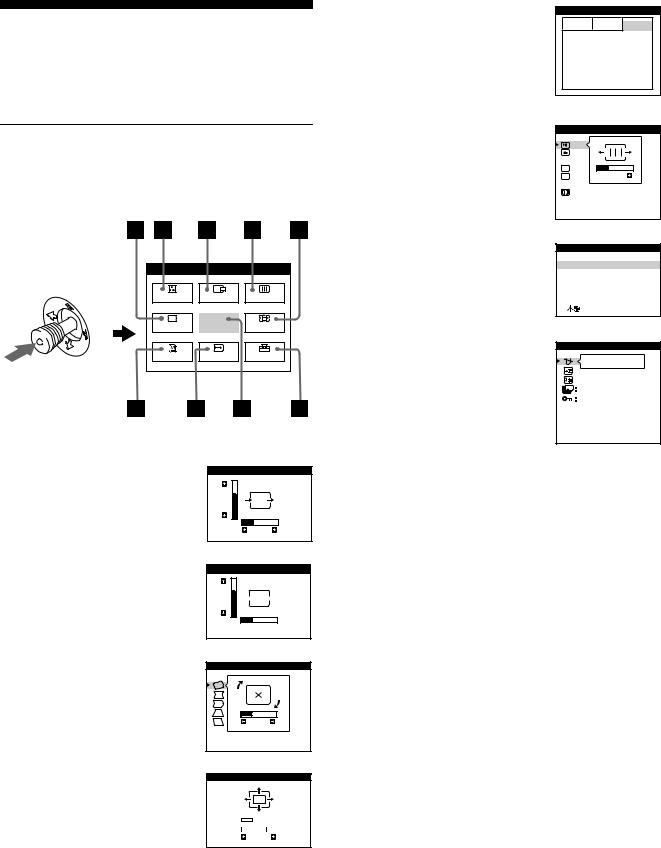
Personnalisation de votre moniteur
Vous pouvez effectuer de multiples réglages sur votre moniteur à l’aide des écrans de menu.
Pilotage par menus
Appuyez sur la manette de commande pour afficher le MENU principal à l’écran. Voir la page 11 pour plus d’informations sur l’utilisation de la manette de commande.
MENU |
|
MENU |
COUL. |
CENTRE |
ECRAN |
GEOM |
QUITTE |
ZOOM |
LANG |
TAILLE |
OPTION |
Utilisez la manette de commande pour sélectionner l’un des menus suivants.
1CENTRE (page 11)
Sélectionne le menu CENTRE pour régler le centrage de l’image.
2TAILLE (page 11)
Sélectionne le menu TAILLE pour régler la taille horizontale et verticale de l’image.
3GEOM (page 12)
Sélectionne le menu GEOM pour régler la rotation et la forme de l’image.
4ZOOM (page 12)
Sélectionne le menu ZOOM pour agrandir ou pour réduire l’image.
CENTRAGE
73
26
TAILLE
73

 26
26 
GEOMETRIE
26
ROTATION
ZOOM
H |
|
|
|
|
|
|
|
|
26 |
|
|
|
|
|
|
|
|
||
V |
|
|
|
|
|
|
|
73 |
|
5COUL. (page 12)
Sélectionne le menu COUL. pour régler la température de couleur de l’image. Vous pouvez utiliser ce menu pour faire correspondre les couleurs du moniteur aux couleurs d’une image imprimée.
COULEUR
5000K 6500K 9300K
R BIAS 

 50 V BIAS

 50 B BIAS

 50 R GAIN

 50 V GAIN

 50 B GAIN

 50
50
6ECRAN (page 13)
Sélectionne le menu ECRAN pour régler la qualité de l’image. Vous pouvez régler la convergence verticale et horizontale, l’alignement et l’effet de suppression de la moire.
7LANG (page 8)
Sélectionne LANG pour choisir la langue d’affichage des menus.
8OPTION (page 14)
Sélectionne OPTION pour régler les options du moniteur. Les options comprennent:
•démagnétisation de l’écran
•changement de la position des écrans de menu
•changement du délai de passage au mode d’économie
•verrouillage des commandes
9QUITTE
Sélectionne QUITTE pour quitter le menu.
ECRAN
 TOP
TOP
 BOT
BOT

 26
26  ADJ
ADJ
CONVERGENCE H
LANGUAGE
 ENGLISH
FRANÇAIS
DEUTSCH
ESPAÑOL
I TALIANO
OPTION
OUI
ZZ... 5 SEC
DEVERR
DEGAUSS MANUEL
10
 Loading...