


3-856-981-11 (1)
Trinitronâ Color Graphic Display
Multiscan17seII
Operating Instructions |
|
|
EN |
|||
|
|
|
|
|
|
|
Mode d’emploi |
|
F |
||||
|
|
|
|
|||
Bedienungsanleitung |
|
D |
||||
|
|
|
|
|
||
Manual de instrucciones |
|
ES |
||||
|
|
|
||||
Istruzioni per l’uso |
|
I |
||||
MODEL: GDM-17SE2T5
ã 1996 by Sony Corporation
Owner’s Record
The model and serial numbers are located at the rear of the unit. Record the serial number in the space provided below. Refer to these numbers whenever you call upon your dealer regarding this product.
Model No. |
|
Serial No. |
WARNING
To prevent fire or shock hazard, do not expose the unit to rain or moisture. Dangerously high voltages are present inside the set. Do not open the cabinet. Refer servicing to qualified personnel only.
This equipment has been tested and found to comply with the limits for a Class B digital device, pursuant to Part 15 of the FCC Rules. These limits are designed to provide reasonable protection against harmful interference in a residential installation. This equipment generates, uses, and can radiate radio frequency energy and, if not installed and used in accordance with the instructions, may cause harmful interference to radio communications. However, there is no guarantee that interference will not occur in a particular installation. If this equipment does cause harmful interference to radio or television reception, which can be determined by turning the equipment off and on, the user is encouraged to try to correct the interference by one or more of the following measures:
–Reorient or relocate the receiving antenna.
–Increase the separation between the equipment and receiver.
–Connect the equipment into an outlet on a circuit different from that to which the receiver is connected.
–Consult the dealer or an experienced radio/TV technician for help.
You are cautioned that any changes or modifications not expressly approved in this manual could void your authority to operate this equipment.
INFORMATION
This product complies with Swedish National Council for Metrology (MPR) standards issued in December 1990 (MPR ll) for very low frequency (VLF) and extremely low frequency (ELF).
INFORMATION
Ce produit est conforme aux normes du Swedish National Council for Metrology de décembre 1990 (MPR ll) en ce qui concerne les fréquences très basses (VLF) et extrêmement basses (ELF).
Hinweis
Dieses Gerät erfüllt bezüglich tieffrequenter (very low frequency) und tiefstfrequenter (extremely low frequency) Strahlung die Vorschriften des „Swedish National Council for Metrology (MPR)“ vom Dezember 1990 (MPR ll).
INFORMACIÓN
Este producto cumple las normas del Consejo Nacional Sueco para Metrología (MPR) emitidas en diciembre de 1990 (MPR ll) para frecuencias muy bajas (VLF) y frecuencias extremadamente bajas (ELF).
Dieses Gerät entspricht den folgenden europäischen EMVVorschriften für Betrieb in Wohngebieten, gewerblichen Gebieten und Leichtindustriegebieten.
EN55022/1987 Klasse B
EN50082-1/1992
EN60555-2/1987
Hinweise
•Aus ergonomischen Gründen wird empfohlen, die Grundfarbe Blau nicht auf dunklem Untergrund zu verwenden (schlechte Erkennbarkeit, Augenbelastung bei zu geringem Zeichenkontrast).
•Aus ergonomischen Gründen sollten nur Darstellungen auf dunklem Hintergrund bei Vertikalfrequenzen ab
60 Hz (ohne Zeilensprung) benutzt werden.
•Die Konvergenz des Bildes kann sich auf Grund des Magnetfeldes am Ort der Aufstellung aus der korrekten Grundeinstellung verändern. Zur Korrektur empfiehlt es sich deshalb, die Regler an der Frontseite für H STAT und V STAT so einzustellen, daß die getrennt sichtbaren Farblinien für Rot, Grün und Blau bei z.B. der Darstellung eines Buchstabens zur Deckung (Konvergenz) gelangen.
Siehe hierzu auch die Erklärungen zu H STAT und V STAT.
NOTICE
This notice is applicable for USA/Canada only.
If shipped to USA/Canada, install only a UL LISTED/CSA LABELLED power supply cord meeting the following specifications:
SPECIFICATIONS Plug Type
Cord
Length
Rating
NOTICE
Cette notice s’applique aux Etats-Unis et au Canada uniquement.
Si cet appareil est exporté aux Etats-Unis ou au Canada, utiliser le cordon d’alimentation portant la mention UL LISTED/CSA LABELLED et remplissant les conditions suivantes: SPECIFICATIONS
Type de fiche Cordon
Longueur
Tension
This monitor complies with the TCO’95 guidelines.
域での電波障害防止を目的とした情報処理装置等電波障 害自主規制協議会VCCI
2
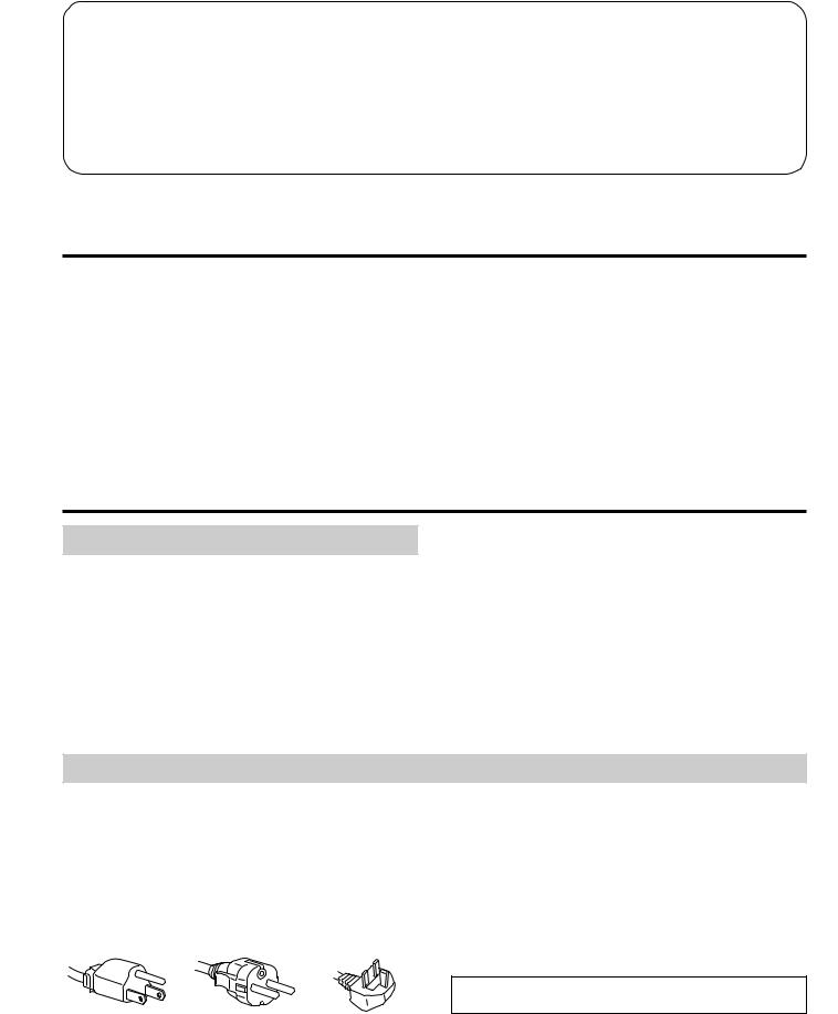
Table of Contents
Introduction .......................................................................... |
3 |
Precautions ............................................................................ |
3 |
Getting Started ...................................................................... |
4 |
Using your Monitor ............................................................. |
5 |
Functions of Controls ........................................................... |
6 |
Adjustments .......................................................................... |
7 |
Power Saving Function ..................................................... |
12 |
Plug and Play ..................................................................... |
12 |
Use of the Tilt-Swivel ........................................................ |
12 |
Damper Wire ...................................................................... |
12 |
Specifications ...................................................................... |
13 |
Troubleshooting ................................................................. |
13 |
Introduction
Congratulations on your purchase of a Sony Multiscan SE series monitor!
This monitor incorporates over 25 years of Sony experience with Trinitron display technology, ensuring excellent performance and outstanding reliability.
The advanced design of the SE series together with Digital Multiscan Technology allows it to sync to any video mode within its wide scan range. In addition, its three factory preset color modes and three user adjustable color modes give you unprecedented flexibility in matching on-screen
colors to hard copy print outs. Furthermore, this monitor features digital controls with OSD (On Screen Display). It delivers easier adjustment by visualizing your control statement. All together, it delivers incredible performance with the quality and support you can expect from Sony.
Precautions
Installation
∙Prevent internal heat build-up by allowing adequate air circulation. Do not place the unit on surfaces (rugs, blankets, etc.) nor near materials (curtains, draperies) that may block the ventilation holes.
∙Do not install the unit near heat sources such as radiators or air ducts, nor in a place subject to direct sunlight, excessive dust, mechanical vibration or shock.
∙Do not place the unit near equipment which generates magnetism, such as a converter or high voltage power lines.
Maintenance |
|
|
|
EN |
|
|
|
|
∙Clean the cabinet, panel and controls with a soft cloth lightly moistened with a mild detergent solution. Do not use any type of abrasive pad, alkaline cleaner, scouring powder or solvent, such as alcohol or benzine.
∙Do not rub, touch, or tap the surface of the screen with sharp or abrasive items, like a ball point pen or a screw driver. Otherwise, this type of contact may result in a scratched picture tube.
Warning on Power Connection
∙Use a proper power cord for your local power supply.
For the customers in U.S.A.
If you do not do this, this monitor will not conform to mandatory FCC standards.
For the customers in UK
If you use the monitor in UK, please use the supplied UK cable with UK plug.
Examples of plug shape:
for 100 to 120 V AC for 220 V to 240 V AC for 240 V AC only
∙Before disconnecting the power cord, wait for at least 30 seconds after turning off the power switch to allow for the discharging of static electricity on the CRT display surface.
∙After the power has been turned on, the CRT is demagnetized for approximately 5 seconds. This generates a strong magnetic field around the bezel, which may affect the data stored on magnetic tapes or disks near the bezel. Place such magnetic recording equipment and tapes/disks apart from this unit.
The socket-outlet should be installed near the equipment and be easily accessible.
3

Getting Started
This monitor will sync with any IBM or compatible system equipped with VGA or greater graphics capability. Although this monitor will sync to other platforms, including Macintosh and Power Macintosh system, a cable adapter is required. Please consult your dealer for advice on which adapter is suitable for your needs.
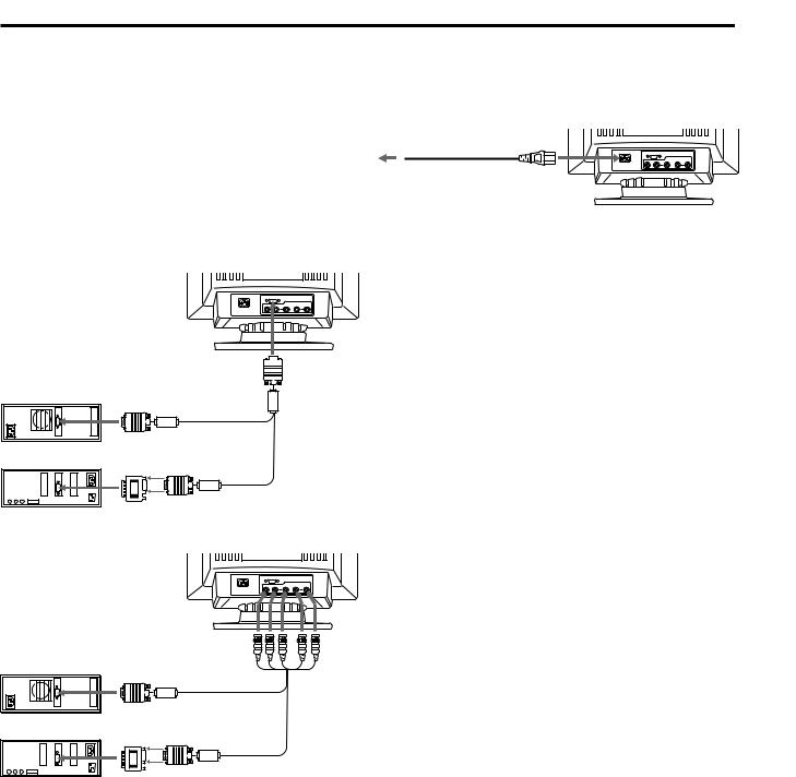
Step 1: With the computer switched off, attach the video signal cable to the monitor (HD15/5 BNC’s) and attach the other end to the video card.
 to HD15
IBM or Compatible Computer
Step 2: With the monitor switched off, attach the power cord to the monitor and the other end to the power outlet.
Power cord (supplied)
to a wall outlet
Step 3: Turn on the monitor and computer.
Step 4: Switch the input connector according to the adjustment procedure on page 10.
Step 5: If necessary, adjust the user controls according to your personal preference.
The installation of your monitor is complete. Enjoy your monitor.
|
to video output |
Video signal cable |
Apple Computer |
|
(supplied) |
to video output |
|
|
|
|
|
|
Macintosh Adapter |
|
|
(supplied) |
|
Notice
To comply with the limits of FCC Class B and IC Class B for digital device, please attach the supplied video signal cable for HD15 input or SMF-400 (sold separately) for BNC input. Furthermore, each cable has ferrite cores on it.
|
|
to |
|
|
VIDEO IN R/G/B |
IBM or Compatible Computer |
SYNC IN HD/VD |
|
|
to video output |
Video signal cable |
|
(not supplied) |
|
Apple Computer |
|
|
to video output |
|
|
|
|
|
Macintosh Adapter (supplied)
Note : Use HD15 (Female)-HD15(Male without No.9 pin) adapter (supplied) for current DOS computer which has no compliance of DDC 2AB and its No.9 pin is disconnected.
4

Using your Monitor
Preset and User Modes
The Multiscan 17seII has factory preset modes for the 10 most popular industry standards for true “plug and play” capability.
When using a video mode that is not one of the 10 factory preset modes, some fine tuning may be required to optimize the display to your preferences. Simply adjust the monitor according to the preceding adjustment instructions. The adjustments will be stored automatically and recalled whenever that mode is used.
A total of 15 user-defined modes can be stored in memory. If the 16th mode is entered, it will replace the first.
For less common modes, and modes that evolve in the future, the Digital Multiscan Technology of the Multiscan 17seII will perform all of the complex adjustments necessary to ensure a high quality picture for any timing in its frequency range. However, due to the wide variety of video boards on the market, it may be necessary for the user to fine tune the vertical/horizontal size and centering.
Recommended horizontal timing conditions
Horizontal sync width duty should be: >4.8% of total horizontal time.
Horizontal blanking width should be: >3.0 µsec.
Note: For Windowsâ4) users, check your video board manual or the utility program which comes with your graphic board and select the highest available refresh rate to maximize monitor performance.
No. |
Resolution |
Horizontal |
Vertical |
|
Graphics |
|
|
||
(dots × lines) |
Frequency |
Frequency |
|
Mode |
|
|
|||
1 |
640 × 480 |
31.5 kHz |
60 Hz |
|
VGA Graphic1) |
|
|
||
2 |
720 × 400 |
31.5 kHz |
70 Hz |
|
VGA Text1) |
|
|
||
3 |
640 × 480 |
43.3 kHz |
85 Hz |
|
VESA2) |
|
|
||
4 |
832 × 624 |
49.7 kHz |
75 Hz |
|
Macintosh |
|
|
||
|
16" Color3) |
|
|
||||||
5 |
800 × 600 |
53.7 kHz |
85 Hz |
|
VESA2) |
|
|
||
6 |
1024 |
× 768 |
60.0 kHz |
75 Hz |
|
Macintosh |
|
|
|
|
19" Color3) |
|
|
||||||
7 |
1280 |
× 1024 |
64.0 kHz |
60 Hz |
|
VESA2) |
|
|
|
8 |
1024 |
× 768 |
68.7 kHz |
85 Hz |
|
VESA2) |
|
|
|
9 |
1152 |
× 870 |
68.7 kHz |
75 Hz |
|
Macintosh |
|
|
|
|
21" Color3) |
|
|
||||||
10 |
1280 |
× 1024 |
80.0 kHz |
75 Hz |
|
VESA2) |
|
|
|
1) VGA is a trademark of IBM Corporation. |
|
|
|
||||||
2) VESA is a trademark of Video Electronics Standard |
|
||||||||
Association. |
|
|
|
|
|
|
|||
3) Macintosh is a trademark of Apple Computer Inc. |
|
||||||||
4) Windowsâ is a registered trademark of Microsoft |
|
||||||||
EN |
|||||||||
Corporation in the United States and other countries. |
|||||||||
|
|||||||||
5
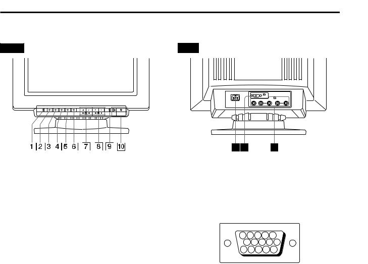
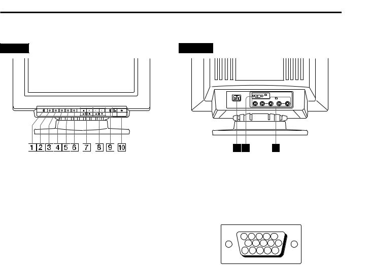
Functions of Controls
See the given pages for further description.
Front |
Rear |
RESET OPTION CONV GEOM SIZE |
CENT |
POWER |
SAVING |
|
|
1 |
|
|
|
|
(HD15) |
2 (BNC) |
|
|
|
|
|
|
R |
G |
B |
HD |
VD |
1RESET button (page 11)
Press to reset the adjustment data to the factory-preset levels.
2OPTION button (page 9-11)
Press to set the option items, such as control lock and color temperature.
3CONV (convergence) button (page 9)
Press to adjust the vertical and horizontal convergence.
4GEOM (geometry) button (page 8)
Press to adjust the rotation and pincushion.
5SIZE (picture size) button (page 8)
Press to adjust the vertical and horizontal picture size.
6CENT (center) button (page 7)
Press to adjust the vertical and horizontal picture position.
7¨ (brightness) –/+ (./>) buttons (page 7-10)
Press to adjust the brightness.
–/+(./>) buttons also adjust the each item.
8> (contrast) –/+ (?//) buttons (page 7-10)
Press to adjust the contrast.
–/+ (?//) buttons also adjust the each item.
9POWER SAVING indicator (page 12)
Lights up when the monitor is in the Power Saving Modes.
0u power switch and indicator (page 12)
Press to turn the monitor on or off. The indicator lights up when the monitor is turned on.
! ¡ AC IN connector
Plug in an AC power cord.
!™ Video input 1 connector (HD15)
The cable accepts RGB video signals (0.714 Vp-p, positive) and SYNC signals.
5 |
4 |
|
3 |
2 |
1 |
|
10 |
9 |
8 |
7 |
6 |
15 14 13 |
12 |
11 |
|||
Pin No. |
Signal |
Pin No. |
Signal |
|
1 |
Red |
8 |
Blue Ground |
|
2 |
Green |
9 |
DDC + 5V* |
|
|
(Composite |
10 |
Ground |
|
|
Sync on Green) |
|||
|
11 |
— |
||
|
|
|||
3 |
Blue |
|||
12 |
Bi-Directional |
|||
4 |
— |
|||
|
Data (SDA)* |
|||
5 |
DDC Ground* |
13 |
H. Sync |
|
6 |
Red Ground |
14 |
V. Sync |
|
7 |
Green Ground |
15 |
Data Clock(SCL)* |
*Display Data Channel (DDC) Standard by VESA
!£ Video input 2 connectors (5 BNC)
The cable accepts RGB video signals (0.714 Vp-p, positive) and SYNC signals.
6
Adjustments
You can adjust the picture to your preference by following the procedure described below.
You can adjust all items on the OSD (On Screen Display). The item being adjusted is indicated in white on the OSD.
Before adjusting the items, turn on the unit and connect a video cable to the computer/work station.
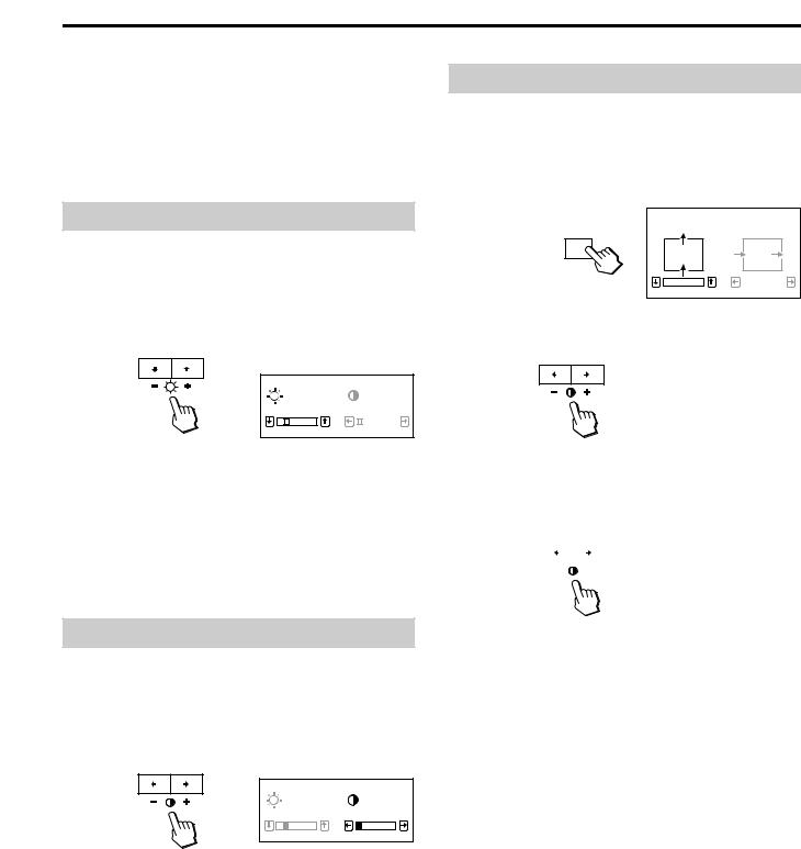
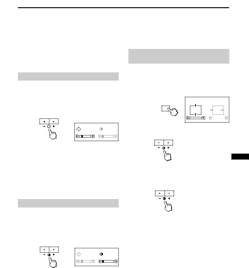
Adjusting the Picture Brightness
The adjustment data becomes the common setting for all input signals received.
1 Press the ¨ ./> button.
The “BRIGHTNESS/CONTRAST” OSD (On Screen Display) appears.
BRIGHTNESS/CONTRAST
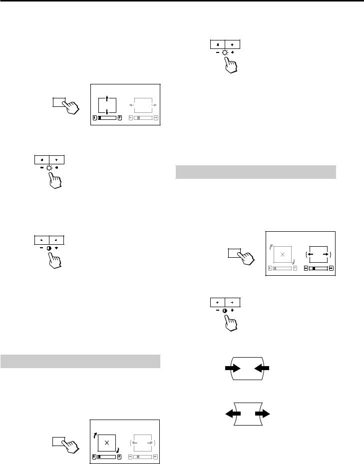
Adjusting the Picture Centering
The adjustment data becomes the unique setting for the input signals received.
1 Press the CENT button.
The “CENTER” OSD (On Screen Display) appears.
CENTER
CENT
|
|
|
0 |
|
23 |
2 For vertical adjustment
Press the ¨ ./> buttons.
|
|
|
23 |
0 |
|
2 Press the ¨ ./> buttons to adjust picture brightness.
. . . . for less brightness > . . . for more brightness
The “BRIGHTNESS/CONTRAST” OSD disappears 3 seconds after you release the buttons.
To reset, press the RESET button while the OSD is on.
Adjusting the Picture Contrast
The adjustment data becomes the common setting for all input signals received.
1 Press the > ?// button.
The “BRIGHTNESS/CONTRAST” OSD (On Screen Display) appears.
BRIGHTNESS/CONTRAST
23 0
2 Press the > ?// button to adjust picture contrast. ? . . . for less contrast
/ . . . for more contrast
The “BRIGHTNESS/CONTRAST” OSD disappears 3 seconds after you release the buttons.
. . . . to move down > . . . to move up
For horizontal adjustment |
|
|||||||||||
EN |
||||||||||||
Press the |
> ?// buttons. |
|||||||||||
|
|
|
|
|
|
|
|
|
|
|
|
|
|
|
|
|
|
|
|
|
|
|
|
|
|
|
|
|
|
|
|
|
|
|
|
|
|
|
? . . . to move left / . . . to move right
To erase the “CENTER” OSD, press the CENT button again. The “CENTER” OSD automatically disappears 10 seconds after you release the buttons.
To reset, press the RESET button while the OSD is on.
To reset, press the RESET button while the OSD is on.
7
Adjustments
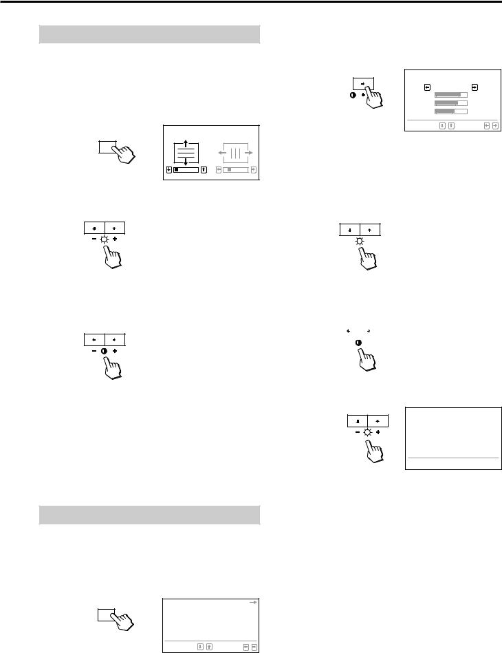
Adjusting the Picture Size |
2 Press the ¨ ./> buttons. |
The adjustment data becomes the unique setting for the input signals received.
1 |
Press the SIZE button. |
|
|
The “SIZE” OSD (On Screen Display) appears. |
|
|
SIZE |
|
|
SIZE |
|
|
0 |
23 |
2 |
For vertical adjustment |
|
|
Press the ¨ ./> buttons. |
|
. . . . to rotate counterclockwise > . . . to rotate clockwise
To erase the “GEOMETRY” OSD, press the GEOM button again.
The “GEOMETRY” OSD automatically disappears 10 seconds after you release the buttons.
To reset, press the RESET button while the OSD is on.
. . . . to diminish > . . . to enlarge
For horizontal adjustment
Press the > ?// buttons.
? . . . to diminish / . . . to enlarge
To erase the “SIZE” OSD, press the SIZE button again. The “SIZE” OSD automatically disappears 10 seconds after you release the buttons.
To reset, press the RESET button while the OSD is on.
Adjusting the Picture Rotation
The adjustment data becomes the common setting for all input signals received.
1 Press the GEOM button.
The “GEOMETRY” OSD (On Screen Display) appears.
|
GEOMETRY |
GEOM |
|
0 |
23 |
Adjusting the Pincushion
The adjustment data becomes the unique setting for the input signals received.
1 Press the GEOM button.
The “GEOMETRY” OSD (On Screen Display) appears.
GEOM
2 Press the > ?// buttons.
|
GEOMETRY |
0 |
23 |
? . . . to diminish the picture sides
/ . . . to expand the picture sides
To erase the “GEOMETRY” OSD, press the GEOM button again.
The “GEOMETRY” OSD automatically disappears 10 seconds after you release the buttons.
8 |
To reset, press the RESET button while the OSD is on. |
Adjusting the Convergence
The adjustment data becomes the common setting for all input signals received.
1 |
Press the CONV button. |
|
|
The “CONVERGENCE” OSD (On Screen Display) |
|
|
appears. |
|
|
CONVERGENCE |
|
|
CONV |
|
|
0 |
23 |
2 |
For vertical adjustment |
|
|
Press the ¨ ./ > buttons. |
|
. . . . to move Red down and Blue up > . . . to move Red up and Blue down
For horizontal adjustment
Press the > ? // buttons.
? . . . to move Red to the left and Blue to the right / . . . to move Red to the right and Blue to the left
To erase the “CONVERGENCE” OSD, press the CONV button again.
The “CONVERGENCE” OSD automatically disappears 10 seconds after you release the buttons.
To reset, press the RESET button while the OSD is on.
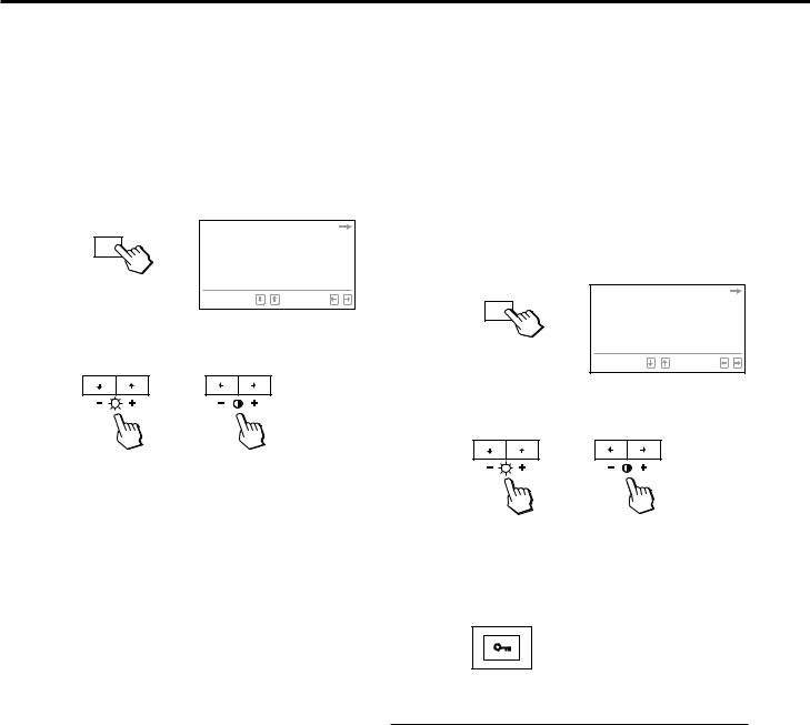
Setting the Color Temperature
The selected color temperature becomes the common setting for all input signals.
1 Press the OPTION button.
The OPTION OSD (On Screen Display) appears.
|
COLOR TEMPERATURE |
|
|
INPUT: |
HD1 5 BNC |
|
LOCK: |
UNLOCK LOCK |
OPTION |
80.0KHz/ 75Hz |
|
|
||
|
SELECT |
SET |
2 Press the > / button.
The “COLOR TEMPERATURE” OSD appears.
COLOR TEMPERATURE
9300K
1 |
2 |
3 |
R |
|
76 |
G |
|
66 |
B |
|
55 |
SELECT |
|
SET |
3 Adjust with the > ?// and ¨ ./> buttons. There are three color temperature modes on the OSD. The factory settings are 1 : 5000K, 2 : 6500K, and 3 : 9300K.
To select 5000K, 6500K or 9300K
Press the > ?// buttons.
|
|
|
|
|
|
|
|
|
|
|
|
|
|
To obtain the desired color temperature |
|
||||||||||||
1 Press the > ?// buttons to select the 1, 2 or 3 |
|
||||||||||||
EN |
|||||||||||||
mode. |
|||||||||||||
|
|||||||||||||
|
|
|
|
|
|
|
|
|
|
|
|
|
|
|
|
|
|
|
|
|
|
|
|
|
|
|
|
|
|
|
|
|
|
|
|
|
|
|
|
|
|
2 Press the ¨ ./> buttons to select R, G or B.
COLOR TEMPERATURE
9300K
1 2 3
R 

 76 G
76 G  66 B
66 B  55
55
SELECT 
 SET
SET 

3Press the > ?// buttons to adjust the color temperature.
The “5000K,” “6500K” or “9300K” disappears. The color temperatures are memorized in the each mode-1, 2 and 3 until you reset each.
To erase the “COLOR TEMPERATURE” OSD, press the OPTION button again.
The OSD automatically disappears 30 seconds after you release the buttons.
To reset, press the RESET button while the OSD is on.
9
Adjustments
Switching the Input Connector |
|
Locking the Controls |
As the monitor has two sets of input connectors, you can switch between two input video signals. It is necessary to select the connector type (HD15/5 BNC's) correctly according to the connection.
1 Press the OPTION button.
The OPTION OSD (On Screen Display) appears.
|
COLOR TEMPERATURE |
|
|
INPUT: |
HD1 5 BNC |
|
LOCK: |
UNLOCK LOCK |
OPTION |
80.0KHz/ 75Hz |
|
|
||
|
SELECT |
SET |
2 Press the ¨ ./> buttons to select “INPUT” and then press the > ?// button to select “HD15” or “BNC.”
/
When you switch between input sources, the monitor screen is muted for a moment (Mute) then the signal through the selected input is displayed. If the selected input do not receive any video signals, the monitor automatically returns to the other input after Mute and the OPTION OSD appears.
To erase the OPTION OSD, press the OPTION button again. The OSD automatically disappears 30 seconds after you release the buttons.
If two computers are connected to the monitor (one to each input), when one of the computers is turned on or restarted, or the monitor goes into power saving mode, the monitor may switch to the other input because the signal is temporarily interrupted. Select the input which you use, following the above steps.
This feature allows you to lock the monitor so that all the buttons, except the u power switch and OPTION button, on the front panel cannot be operated (Lock mode). Hence, your settings cannot be modified. With this function, you can ensure that your settings will remain the same even when the control buttons are exposed to others.
To release the Lock mode, set it to off (UNLOCK) position. Normally keep this function set to off (UNLOCK) position.
1 Press the OPTION button.
The OPTION OSD (On Screen Display) appears.
|
COLOR TEMPERATURE |
|
|
INPUT: |
HD1 5 BNC |
|
LOCK: |
UNLOCK LOCK |
OPTION |
80.0KHz/ 75Hz |
|
|
||
|
SELECT |
SET |
2 Press the ¨./> buttons to select “LOCK” and then press the >?// buttons to select “LOCK.”
/
The ¨ ./> buttons do not work on the OPTION OSD. The control buttons on the front panel except the OPTION button do not work. If you press any button except the
u power switch and OPTION button, the 

 mark appears on the screen.
To Cancel the Control Lock
Press the OPTION button again.
Press the > ?// buttons to select “UNLOCK.”
To erase the OPTION OSD, press the OPTION button again. The OSD automatically disappears 30 seconds after you release the buttons.
10
Checking the Signal Frequency
It is possible to check the current vertical and horizontal frequencies of the input signal received.
Press the OPTION button.
The OPTION OSD (On Screen Display) appears.
|
COLOR TEMPERATURE |
|
|
INPUT: |
HD1 5 BNC |
|
LOCK: |
UNLOCK LOCK |
OPTION |
80.0KHz/ 75Hz |
|
|
||
|
SELECT |
SET |
Horizontal Vertical frequency frequency
Resetting the Adjustment Data to Factory-preset Levels
To reset an adjustment item
If you want to reset the color temperature
Select one of the three color temperature modes, (See “Setting the Color Temperature” on page 9), and then press the RESET button before the OSD (On Screen Display) disappears.
If you want to reset the other adjustment items
Press the button of the adjustment item you want to reset, and then press the RESET button before the OSD (On Screen Display) disappears.
To reset the brightness, contrast, size, center and pincushion adjustment data at once (for the received signal)
Press the RESET button with something like a coin for one second when no OSD is shown.
EN
RESET
To reset all adjustment data to factorypreset levels
Press and hold the RESET button for more than 2 seconds. All adjustment data including the brightness and contrast are reset to factory-preset levels.
RESET
11
Power Saving
Function
This monitor is capable of 3 states of reduced power consumption.
By sensing the absence of one or both sync signals coming from the host computer, it will reduce power consumption as follows.
|
|
Power |
Required |
POWER |
u (power) |
|
Mode |
State |
resumption |
SAVING |
|||
consumption |
indicator |
|||||
|
|
|
time |
indicator |
|
|
1 |
Normal |
≤ 140 W |
— |
off |
green on |
|
operation |
||||||
|
|
|
|
|
||
|
Standby |
|
|
|
|
|
2 |
(1st step |
≤ 100 W |
approx. |
orange on |
green on |
|
of power |
3 sec. |
|||||
|
|
|
|
|||
|
saving) |
|
|
|
|
|
|
Suspend |
|
approx. |
|
|
|
3 |
(2nd step |
≤ 15 W |
orange on |
green on |
||
|
of power |
|
3 sec. |
|
|
|
|
saving) |
|
|
|
|
|
|
Active-off |
|
|
|
|
|
4 |
(3rd step |
≤ 5 W |
approx. |
orange on |
off |
|
of power |
10 sec. |
|||||
|
|
|
|
|||
|
saving) |
|
|
|
|
|
5 |
Power-off |
0 W |
— |
off |
off |
Power Saving Operation
The H-sync is not present.
.
The unit goes into standby state.
The V-sync is not present.
.
The unit goes into suspend state.
Both the H-sync and V-sync are not present.
.
The unit goes into active-off state.
The monitor requires a videocard or screen saver software which switches off one or both sync signals to activate the power saving function.
Caution: The Power Saving function will automatically put the monitor into the Active-off state if the power switch is turned on without any video signal input. Once the horizontal and vertical syncs are sensed, the monitor will automatically return to its Normal operation state.
Plug and Play
This monitor complies with the DDCTM1, DDC2B and DDC2AB which are the Display Data Channel (DDC) standards of VESA.
When a DDC1 host system is connected, the monitor synchronizes with the V. CLK in accordance with the VESA standards and outputs the EDID (Extended Display Identification) to the data line.
When a DDC2B or DDC2AB host system is connected, the monitor automatically switches to each communication.
DDCTM is a trademark of Video Electronics Standard Association.
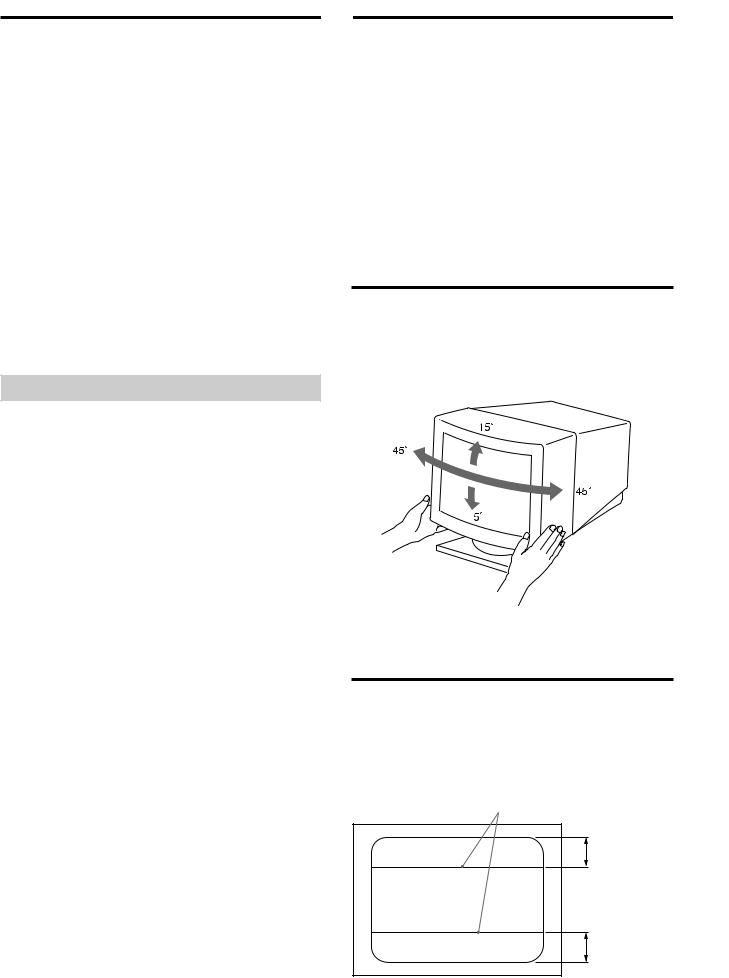
Use of the Tilt-Swivel
With the tilt-swivel, this unit can be adjusted to be viewed at your desired angle within 90° horizontally and 20° vertically.
To turn the unit vertically and horizontally, hold it at its bottom with both hands as illustrated below.
Damper Wire
Using a white background, very thin horizontal stripes on the screen are visible as shown below. These stripes are damper wires. These wires are attached to the aperture grille inside the Trinitron tube and are there to damp vibrations of the aperture grille in order to prevent them from influencing to the picture quality.
Damper wire
Approx. 6 cm
12 |
Approx. 6 cm |
|

Specifications
Picture tube |
0.25 mm aperture grille pitch |
|
17 inches measured diagonally |
|
90-degree deflection |
Viewable image size Approx. 327 × 241 mm (w/h)
|
(12 7/8 × 9 1/2 inches) |
|
15.9” viewing image |
Resolution |
Horizontal: Max. 1280 dots |
|
Vertical: Max. 1024 lines |
Standard image area |
Approx. 300 × 225 mm (w/h) |
|
|
|
(11 7/8 × 8 7/8 inches) |
|
or |
|
Aprrox. 293 × 234 mm (w/h) |
|
(11 5/8 × 9 1/4 inches) |
Deflection frequency |
|
|
Horizontal: 30 to 85 kHz |
|
Vertical: 48 to 150 Hz |
AC input voltage/current |
|
|
100 to 120 V, 50/60 Hz, 1.7 A |
|
220 to 240 V, 50 – 60 Hz, 1.2 A |
Power comsumption |
|
|
Max. 140 W |
Dimensions |
403.6 × 426.3 × 450 mm (w/h/d) |
|
(16 × 16 7/8 × 17 3/4 inches) |
Mass |
Approx. 20 kg (44 lb) |
Design and specifications are subject to change without notice.
Troubleshooting
This section may help you isolate a problem and as a result, eliminate the need to contact technical support, allowing continued productivity.
No picture
/If neither the u (power) indicator nor the POWER SAVING indicator is not lit.
—Check that the power cord is properly connected.
—Check that the power switch is in the “on” position.
/If the POWER SAVING indicator is lit.
—Check that your computer power switch is in the “on” position.
—The monitor will recover when you press any key on the keyboard of the computer.
—Check that the video cable is properly connected and all plugs are firmly seated in their socket.
—Check that the 5 BNC's are connected in the right order (from power cord side: Red- Green-Blue-HD-VD).
—Ensure that no pins are bent or pushed in the HD15 connector of the cable.
—Check that the video card is seated completely in a proper bus slot.
—Check that the video frequency range is
within that specified for the monitor. |
EN |
— If using a Macintosh system, check that the |
|
|
|
Macintosh adapter and the video signal |
|
cable are properly connected. |
|
/ If the u (power) and/or the POWER SAVING |
|
indicators are both flashing. |
|
— Turn the monitor off and on. If the indicator |
|
is off, the monitor is in the normal |
|
condition. If the indicator is still flashing, |
|
there is a potential monitor failure. |
|
/ If you do the above procedures and the |
|
monitor does not recover. |
|
— Unplug the video cable (HD15/5 BNC's) |
|
then press and hold the > + button for 2 |
|
seconds to display the color bars. Then, |
|
turn the monitor off and on by pressing the |
|
u power switch. |
|
If the monitor does not recover, the monitor |
|
is out of order. |
|
Picture is scrambled
/Check your graphics board manual for the proper monitor setting on your Multiscan 17seII.
/Check this manual and confirm that the graphic mode and the frequency at which you are trying to operate is supported. Even within the proper range some video boards may have a sync pulse that is too narrow for the monitor to sync correctly.
13

Troubleshooting
Color is not uniform
/Trip the u power switch once to activate the Auto-degauss cycle. This function is to demagnetize the metal frame of the CRT to obtain neutral field for uniform color reproduction. If a second degauss cycle is needed, allow a minimum interval of 20 minutes for the best result.
You cannot adjust the monitor with the buttons on the front panel
/If the control lock is set to on, set it to off using the OPTION OSD. (page 10)
You will be able to adjust the monitor.
White does not look white
/Adjust color temperature using the OPTION OSD. (page 9)
/Check that the 5 BNC’s are connected in the right order (from power cord side: Red- Green-Blue-HD-VD).
Screen image is not centered or sized properly
/Adjust centering, size or geometry using the OSD. (page 7, 8)
/Some video modes do not fill the screen to the edge of the monitor. There is no single answer to solve the problem. There is a tendency to have this problem on higher refresh timings.
Edges of the image are curved
/Adjust pincushion using the OSD. (page 8)
White lines show red or blue shades at edges
/Adjust the convergence using the OSD. (page 9)
Picture is fuzzy
/Adjust the contrast and brightness using the OSD (page 7).
/Trip the u power switch once to activate the Auto-degauss cycle. This function demagnetizes the metal frame of the CRT to obtain neutral field for uniform color reproduction. If a second degauss cycle is needed, allow a minimum interval of 20 minutes for the best result.
/If red or blue shades are found at the edge of images, adjust convergence using the OSD. (page 9)
Picture bounces or has wavy oscillations
/Isolate and eliminate any potential sources of electric or magnetic fields. Common causes for this symptom are electric fans, fluorescent lighting, laser printers, and so on.
/If you have another monitor close to this monitor, increase the distance between them to reduce the interference.
/Try plugging the monitor into a different AC outlet, preferably on a different circuit.
/Try the monitor on a completely different computer in a different room.
Picture appears to be ghosting
/Eliminate the use of video cable extension cable and/or video switch boxes if this symptom occurs. Excessive cable length or weak connection can produce this symptom.
Two fine horizontal lines (wires) are visible
/These wires stabilize the vertically striped Aperture Grille. This Aperture Grille allows more light to pass through to the screen giving the Trinitron CRT more color and brightness.
Wavy or elliptical (moire) pattern is visible
/Due to the relationship between resolution, monitor dot pitch and the pitch of some image patterns, certain screen backgrounds, especially gray, sometimes show moire. This can only be eliminated by changing your desktop pattern.
•If the problem persists, call your authorized Sony dealer from a location near your monitor.
•Note the model name and the serial number of your monitor. Also note the make and name of your computer and video board.
14
Table des matières
Introduction ........................................................................ |
15 |
Précautions .......................................................................... |
15 |
Préparation .......................................................................... |
16 |
Utilisation de votre moniteur ........................................... |
17 |
Fonction des commandes .................................................. |
18 |
Réglages ............................................................................... |
19 |
Economie d’énergie ........................................................... |
24 |
Un moniteur prêt à l’emploi ............................................ |
24 |
Utilisation du support pivotant ....................................... |
24 |
Fil d’amortissement ........................................................... |
24 |
Spécifications ...................................................................... |
25 |
Dépannage .......................................................................... |
25 |
Introduction
Nous vous félicitons d’avoir fait l’acquisition d’un moniteur Multiscan SE Sony !
Ce moniteur intègre plus de 25 années d’expérience de Sony en matière de technologie d’affichage Trinitron, qui vous garantit d’excellentes performances et une fiabilité exceptionnelle.
La conception avancée des moniteurs SE et la technologie Multiscan numérique lui permettent de se synchroniser sur n’importe quel mode vidéo dans sa vaste plage de balayage.
De plus, avec trois modes de couleur par défaut et trois modes de couleur réglables par l’utilisateur, il assure une flexibilité inégalée en matière de correspondance des couleurs d’affichage et d’impression. Ce moniteur est par ailleurs doté de commandes numériques et du système OSD (menus d’affichage). Il se règle d’une façon très simple en visualisant vos réglages. Bref, il allie des performances exceptionnelles à la qualité et à la fiabilité que vous êtes en droit d’attendre d’un Sony.
Précautions
Installation
∙Veillez à assurer une circulation d’air adéquate pour éviter une surchauffe interne de l’appareil. Ne placez pas l’appareil sur des surfaces textiles (tapis, couvertures, etc.) ni à proximité de rideaux ou de draperies susceptibles d’obstruer les orifices de ventilation.
∙N’installez pas l’appareil à proximité de sources de chaleur telles qu’un radiateur ou une conduite d’air chaud, ni dans un endroit exposé à la lumière directe du soleil, à des poussières excessives, à des vibrations ou à des chocs mécaniques.
∙N’installez pas l’appareil à proximité d’un équipement qui génère un champ magnétique, comme un convertisseur ou des lignes à haute tension.
Entretien
∙ Nettoyez le châssis, le panneau de verre et les |
F |
commandes à l’aide d’un chiffon doux légèrement |
|
imprégné d’une solution détergente douce. N’utilisez |
|
jamais de tampons abrasifs, d’ammoniaque, de poudre à |
|
récurer ni de solvants tels que l’alcool ou le benzène. |
|
•Ne frottez pas, ne touchez pas et ne tapotez pas la surface de l’écran avec des objets abrasifs ou aigus comme un stylo à bille ou un tournevis. Ce type de contact risque en effet de rayer le tube image.
Avertissement: raccordement électrique
∙Utilisez un cordon d’alimentation approprié à votre tension secteur locale.
Pour les clients aux Etats-Unis
Si vous ne le faites pas, ce moniteur ne sera pas conforme aux normes FCC en vigueur.
Pour les clients au Royaume-Uni
Si vous utilisez ce moniteur au Royaume-Uni, utilisez le cordon et la fiche pour le Royaume-Uni fournis.
Exemples de formes de fiche
pour CA 100 à 120 V pour CA 220 à 240 V pour CA 240 V uniquement
∙Avant de débrancher le cordon d’alimentation, attendez au moins 30 secondes après avoir mis l’interrupteur d’alimentation en position “off”, de manière à permettre la décharge de l’électricité statique sur la surface de l’écran CRT.
∙Après que le courant a été branché, le CRT est démagnétisé pendant environ 5 secondes. Cela génère un puissant champ magnétique autour de l’encadrement qui peut affecter les données mémorisées sur une bande magnétique ou des disquettes situées à proximité. Placez ces systèmes d’enregistrement magnétique et ces bandes/ disquettes à l’écart de cet appareil.
La prise murale doit être installée à proximité de l’équipement et être aisément accessible.
15
Préparation
Ce moniteur se synchronise sur n’importe quel système IBM ou compatible équipé d’une carte VGA ou de capacités graphiques supérieures. Bien que ce moniteur se synchronise sur d’autres plate-formes, y compris Macintosh et Power Macintosh, un adaptateur de câble est indispensable. Consultez votre distributeur pour des conseils relatifs à l’adaptateur répondant à vos besoins.
1re étape: L’ordinateur étant hors tension, branchez le câble de signal vidéo sur le moniteur (HD15/5 BNC’S) et raccordez l’autre extrémité à la carte vidéo.
 vers HD15
Ordinateur IBM ou compatible
|
vers la sortie vidéo |
Câble de signal |
Ordinateur Apple |
|
vidéo (fourni) |
vers la sortie vidéo |
|
|
|
|
|
|
Adaptateur Macintosh |
|
|
(fourni) |
|
2e étape: Le moniteur étant hors tension, raccordez le cordon d’alimentation au moniteur et l’autre extrémité à la prise murale.
Cordon d’alimentation (fourni)
Vers une prise murale
3e étape: Mettez le moniteur et l’ordinateur sous tension.
4e étape: Commutez le connecteur d’entrée suivant la procédure de réglage décrite à la page 22.
5e étape: Si nécessaire, réglez les commandes utilisateur selon vos préférences personnelles.
L’installation de votre moniteur est terminée. Nous vous souhaitons beaucoup de plaisir avec votre moniteur.
Notice
Pour satisfaire aux normes de FCC Class B et IC Class B pour les appareils numériques, raccordez le câble de signal vidéo fourni pour l’entrée HD15 ou SMF-400 (vendu séparément) pour l’entrée BNC. Par ailleurs, chaque câble est composé d’âmes en ferrite.
|
vers VIDEO IN R/G/B |
Ordinateur IBM ou compatible |
SYNC IN HD/VD |
|
|
vers la sortie vidéo |
Câble de signal |
vidéo (non fourni) |
Ordinateur Apple
vers la sortie vidéo
Adaptateur Macintosh (fourni)
Remarque: Utilisez un adaptateur HD15 (femelle) - HD15 (mâle sans broche No.9) (fourni) pour l'ordinateur DOS actuel qui n'est pas conforme aux spécifications DDC 2AB et dont la broche No.9 est déconnectée.
16

Utilisation de votre moniteur
Modes par défaut et modes utilisateur
Le Multiscan 17seII comporte des modes par défaut pour les dix normes industrielles les plus courantes, ce qui le rend véritablement “prêt à l’emploi”.
Si vous utilisez un mode vidéo qui ne fait pas partie des 10 modes par défaut, il est possible que vous deviez procéder à une syntonisation fine manuelle de manière à optimiser l'affichage en fonction de vos préférences. Il vous suffit pour cela de régler le moniteur en appliquant les instructions de réglage ci-dessus. Les réglages seront automatiquement enregistrés et restaurés chaque fois que ce mode sera activé. Au total, 15 modes utilisateur peuvent être enregistrés dans la mémoire. Si vous enregistrez un seizième mode, il remplacera le premier dans la mémoire.
Pour les modes moins courants, et les modes qui seront utilisés à l’avenir, la technologie Multiscan numérique du Multiscan 17seII réalise tous les réglages complexes nécessaires pour assurer une haute qualité d’image pour n’importe quelle synchronisation dans sa plage de fréquences. En raison de la grande diversité de cartes vidéo disponibles sur le marché, il peut cependant s’avérer nécessaire d’effectuer le réglage fin de la taille et du centrage vertical/horizontal.
Conditions de synchronisation horizontale préconisées
Largeur de synchronisation horizontale : > 4,8% de la durée horizontale totale.
Largeur de neutralisation horizontale : > 3,0 µs
Remarque: Les utilisateurs Windowsâ 4) doivent contrôler le manuel de leur carte vidéo ou le programme utilitaire fourni avec la carte graphique et sélectionner le taux de régénération le plus élevé de manière à maximiser les performances du moniteur.
N’ |
Résolution |
Fréquence |
Fréquence |
Mode |
|
|
|
(points × lignes) |
horizontale |
verticale |
graphique |
|
|
||
1 |
640 × 480 |
31,5 kHz |
60 Hz |
VGA Graphic1) |
|
|
|
2 |
720 × 400 |
31,5 kHz |
70 Hz |
VGA Text1) |
|
|
|
3 |
640 × 480 |
43,3 kHz |
85 Hz |
VESA2) |
|
|
|
4 |
832 × 624 |
49,7 kHz |
75 Hz |
Macintosh |
|
|
|
|
|
|
|
16" Color3) |
|
|
|
5 |
800 × 600 |
53,7 kHz |
85 Hz |
VESA2) |
|
|
|
6 |
1024 × 768 |
60,0 kHz |
75 Hz |
Macintosh |
|
|
|
19" Color |
3) |
|
|
||||
|
|
|
|
|
|
|
|
7 |
1280 × 1024 |
64,0 kHz |
60 Hz |
VESA2) |
|
|
|
8 |
1024 × 768 |
68,7 kHz |
85 Hz |
VESA2) |
|
|
|
9 |
1152 × 870 |
68,7 kHz |
75 Hz |
Macintosh |
|
|
|
21" Color3) |
|
|
|||||
10 |
1280 × 1024 |
80,0 kHz |
75 Hz |
VESA2) |
|
|
|
1) VGA est une marque déposée de IBM Corporation. |
|
|
|
||||
2) VESA est une marque déposée de Video Electronics |
|
|
|
||||
|
Standard Association. |
|
|
|
|
|
|
3) Macintosh est une marque déposée de Apple Computer |
|
||||||
|
Inc. |
|
|
|
|
|
|
4) Windowsâ est une marque déposée de Microsoft |
|
|
|
||||
|
Corporation enregistrée aux Etats-Unis et dans d’autres |
|
|||||
|
F |
||||||
|
pays. |
|
|
|
|
|
|
|
|
|
|
|
|
|
|
17
Fonction des commandes
Référez-vous aux pages indiquées pour une description détaillée.
Avant |
Arrière |
RESET OPTION CONV GEOM SIZE |
CENT |
POWER |
SAVING |
|
|
1 |
|
|
|
|
(HD15) |
2 (BNC) |
|
|
|
|
|
|
R |
G |
B |
HD |
VD |
1Touche RESET (réinitialisation, page 23)
Permet de réinitialiser les réglages en rétablissant les valeurs d’usine.
2Touche OPTION (option, pages 21-23)
Appuyez sur cette touche pour régler les paramètres optionnels comme le verrouillage de commande et la température de couleur.
3Touche CONV (convergence, page 21)
Permet de régler la convergence verticale et horizontale.
4Touche GEOM (géométrie, page 20)
Permet d’ajuster la rotation et la distorsion en coussin.
5Touche SIZE (taille, page 20)
Permet d’ajuster la taille de l’image, verticalement et horizontalement.
6Touche CENT (centrer, page 19)
Permet d’ajuster la position verticale et horizontale de l’image.
7Touches ¨ –/+ (./>) (luminosité, pages 19-22)
Permettent d’ajuster la luminosité.
Les touches –/+ (./>) permettent également d’ajuster les différents réglages.
8Touches > –/+ (?//) (contraste, pages 19-22)
Permettent d’ajuster le contraste.
Les touches –/+ (?//) permettent également d’ajuster les différents réglages.
9Indicateur POWER SAVING (économie d’énergie, page 24)
S’allume lorsque la fonction d’économie d’énergie est active.
0Interrupteur et indicateur d’alimentation u
(page 24)
Permet de mettre l’écran sous/hors tension. Le témoin s’allume lorsque l’écran est sous tension.
! ¡ Connecteur AC IN
Pour le cordon d’alimentation secteur.
!™ 1 Connecteur d’entrée vidéo (HD15)
Le câble accepte les signaux vidéo RVB (0,714 Vp-p, positif) et les signaux SYNC.
5 |
4 |
|
3 |
2 |
1 |
|
10 |
9 |
8 |
7 |
6 |
15 14 13 |
12 |
11 |
|||
Broche |
Signal |
Broche |
Signal |
|
1 |
Rouge |
8 |
Masse du bleu |
|
2 |
Vert |
9 |
DDC + 5 V* |
|
|
(synchronisation |
10 |
Masse |
|
|
composite sur le |
|
|
|
|
11 |
— |
||
|
vert) |
|||
|
|
|
||
|
12 |
Données |
||
|
|
|||
3 |
Bleu |
|||
|
bidirectionnelles |
|||
4 |
— |
|
(SDA)* |
|
5 |
Masse DDC* |
13 |
Sync H |
|
6 |
Masse du rouge |
14 |
Sync V |
|
7 |
Masse du vert |
15 |
Horloge (SCL)* |
*Standard VESA Display Data Channel (DDC)
!£ 2 Connecteurs d’entrée vidéo (5 BNC)
Le câble accepte les signaux vidéo RVB (0,714 Vp-p, positif) et les signaux SYNC.
18
Réglages
Vous pouvez régler l’image suivant vos préférences personnelles en appliquant la procédure décrite ci-dessous. Vous pouvez régler tous les paramètres dans les menus d’affichage OSD.
Le paramètre en cours de réglage est affiché en blanc dans le menu.
Avant de procéder au réglage des paramètres, mettez l’appareil sous tension et branchez un câble vidéo à l’ordinateur/poste de travail.
Réglage de la luminosité
La valeur introduite devient le réglage commun à tous les signaux d’entrée.
1 Appuyez sur la touche ¨ ./>.
L’écran “BRIGHTNESS/CONTRAST” OSD (On Screen Display) apparaît.
BRIGHTNESS/CONTRAST
23 0
L’écran “BRIGHTNESS/CONTRAST” OSD disparaît 3 secondes après que vous avez relâché les touches.
Pour réinitialiser le réglage, appuyez sur la touche RESET pendant que le menu est affiché.
Réglage du centrage de l’image
La valeur introduite devient le réglage unique pour tous les signaux d’entrée.
1 Appuyez sur la touche CENT.
L’écran “CENTER” OSD (On Screen Display) apparaît.
CENTER
CENT
|
|
|
0 |
|
23 |
2 Pour le réglage du centrage vertical
Appuyez sur les touches ¨ ./>.
2 Appuyez sur les touches ¨ ./> pour régler la luminosité de l’image.
. . . . pour moins de luminosité > . . . pour plus de luminosité
L’écran “BRIGHTNESS/CONTRAST” OSD disparaît 3 secondes après que vous avez relâché les touches.
Pour réinitialiser le réglage, appuyez sur la touche RESET pendant que le menu est affiché.
F
. . . . pour abaisser l’image > . . . pour remonter l’image
Pour le réglage du centrage horizontal
Appuyez sur les touches > ?//.
Réglage du contraste
La valeur introduite devient le réglage commun à tous les signaux d’entrée.
1 |
Appuyez sur la touche > ?//. |
|
|
L’écran “BRIGHTNESS/CONTRAST” OSD (On Screen |
|
|
Display) apparaît. |
|
|
BRIGHTNESS/CONTRAST |
|
|
23 |
0 |
2 |
Appuyez sur les touches > ?// pour régler le |
|
|
contraste de l’image. |
|
? . . . pour moins de contraste / . . . pour plus de contraste
? . . . pour déplacer l’image vers la gauche / . . . pour déplacer l’image vers la droite
Pour faire disparaître l’écran “CENTER” OSD, appuyez de nouveau sur la touche CENT.
L’écran “CENTER” OSD disparaît automatiquement 10 secondes après que vous avez relâché les touches.
Pour réinitialiser le réglage, appuyez sur la touche RESET pendant que le menu est affiché.
19
 Loading...