


 Loading...
3-869-710-14(1)
Live Content
Producer
Operating Instructions
Software Version 1.30
AWS-G500
©2005 Sony Corporation

Table of Contents
Usage Notes ............................................................................ |
9 |
Chapter 1 Overview
Features of This System ....................................................... |
11 |
Example Applications ........................................................... |
13 |
Names and Functions of Parts ............................................ |
15 |
Front Panel............................................................................ |
15 |
Rear Panel............................................................................. |
19 |
Side Panel ............................................................................. |
23 |
Other Parts ............................................................................ |
24 |
Operation Screen .................................................................. |
25 |
Menu Operations .................................................................. |
30 |
Operation screen (Text Typing Tool Software) ................... |
33 |
Chapter 2 Preparations
Installation/Default Settings ................................................. |
41 |
Installing the Unit ................................................................. |
41 |
Fitting a Keyboard ................................................................ |
42 |
Starting and Closing Down the Unit .................................... |
44 |
Selecting the Keyboard Language........................................ |
46 |
Setting the Time Zone .......................................................... |
46 |
Setting the Date and Time .................................................... |
47 |
Adjusting the Display Brightness ......................................... |
47 |
Selecting the Video Output Signal Format........................... |
48 |
Connections .......................................................................... |
49 |
Connecting a Camera with VISCA Support......................... |
50 |
Connecting a Microphone .................................................... |
50 |
Connecting a Computer (RGB Input)................................... |
51 |
Connecting a Camcorder ...................................................... |
51 |
Connecting a VCR................................................................ |
52 |
Connecting an External Hard Disk....................................... |
52 |
Connecting a Plasma Display/Projector/Monitor................. |
53 |
Connecting an Amplifier ...................................................... |
54 |
Preventing Accidental Cable Disconnection ........................ |
54 |
Installing Option Modules .................................................... |
55 |
Settings Related to Input Signals ........................................ |
56 |
Relation Between Input Signals and System Components... |
56 |
Video Signal Related Settings .............................................. |
57 |
Audio Signal Related Settings.............................................. |
59 |
Relation Between Program Output Display and Input and |
|
Output Formats ................................................................ |
63 |
2

Chapter 3 Operations
Video Switching .................................................................... |
65 |
Basics of Video Switching ................................................... |
65 |
Changing the Video with a Cut ............................................ |
66 |
Changing the Video with a Effect Transition....................... |
68 |
Changing the Transition Time.............................................. |
72 |
Changing the Effect Pattern.................................................. |
73 |
Using Picture-in-Picture (PinP) for Combining Videos ....... |
73 |
Adjusting the Picture-in-Picture (PinP)................................ |
75 |
Using Fade-to-Black (FTB).................................................. |
77 |
Using Color Bars and Color Mattes ..................................... |
78 |
Using the Downstream Key (DSK) Function to Add Text |
|
or an Image ..................................................................... |
78 |
Showing a Logo on the Screen ............................................. |
82 |
Using Luminance Keying..................................................... |
84 |
Adjusting the Combined Video ............................................ |
86 |
Cropping Unwanted Portions From the Video Being |
|
Combined........................................................................ |
87 |
Applying Edge Effects ......................................................... |
87 |
Checking the Results of Combining Videos |
|
(Effect Preview).............................................................. |
88 |
Giving Priority to Displaying the PVW Viewer................... |
90 |
Creating a Title Graphic with the Text Typing Tool ........... |
91 |
Features of the Text Typing Tool Software ......................... |
91 |
Flow of Operations ............................................................... |
92 |
Starting Up............................................................................ |
94 |
Closing Down....................................................................... |
95 |
Standard Operations ............................................................. |
95 |
File Operations ..................................................................... |
98 |
Working on Text Objects ................................................... |
104 |
Working on Line Objects ................................................... |
111 |
Shadow Operations............................................................. |
113 |
Background Color Operations (Creating Telop and Flip) .. |
115 |
Color Operations ................................................................ |
118 |
Object Layout ..................................................................... |
122 |
Adding and Deleting Sheets ............................................... |
125 |
Simulating the Keying Effects............................................ |
125 |
Key Combination in the Anycast Station Main Software .. |
127 |
Importing a Font File.......................................................... |
129 |
Deleting a Font File ............................................................ |
130 |
Controlling Cameras ........................................................... |
132 |
Registering Cameras to be Controlled................................ |
132 |
Controlling Camera Manually............................................ |
133 |
Storing a Camera Preset ..................................................... |
134 |
Setting the Camera Control ................................................ |
137 |
Resetting the Camera.......................................................... |
138 |
About Camera Tallies......................................................... |
139 |
Audio Mixing ........................................................................ |
141 |
3

Recording Video and Audio on an External Device ......... |
142 |
Recording Program Output on a VCR................................ |
142 |
Recording Inputs on an External Hard Disk....................... |
144 |
Operations on Files on the External Hard Disk.................. |
147 |
Disconnecting the External Hard Disk ............................... |
150 |
Recovering an External Hard Disk..................................... |
151 |
Using a Computer to Play Files Recorded on an External |
|
Hard Disk ........................................................................ |
153 |
Using the Intercom Function ............................................. |
154 |
Connecting the Intercom System........................................ |
154 |
Speaking on the Intercom System ...................................... |
155 |
Monitoring Audio ................................................................ |
156 |
Determining the Audio Signal Output Destinations........... |
156 |
Displaying the Audio Signal Output Destinations ............. |
157 |
Monitoring Output Audio................................................... |
158 |
Monitoring the Audio of a Particular Channel Only .......... |
159 |
Video/Audio Signal Adjustments and Settings ................ |
160 |
Adjusting Analog Video Input Signals............................... |
160 |
Making the Gradation of SDI Input Signals Appear Smooth |
|
(When Using the Serial Digital Interface Module)....... |
161 |
Adjusting the Clock Phase of RGB Signals ....................... |
161 |
Adjusting Color Matte ........................................................ |
161 |
Applying an Offset to the Program Output Video.............. |
162 |
Setting the RGB Output Signal Format.............................. |
162 |
Applying Filters to the Program Output Video .................. |
163 |
Adjusting the Audio Input Signal Levels ........................... |
164 |
Cutting High Frequency or Low Frequency....................... |
164 |
Adjusting the Equalizer ...................................................... |
165 |
Using the Limiter or Compressor ....................................... |
166 |
Adjusting the Audio Left and Right Channel Balance....... |
166 |
Adjusting the Output Levels for Each Destination............. |
166 |
If the Output Video Is Delayed with Respect to the Audio 167 |
|
Adjusting the Output Using the Oscillator Signal .............. |
168 |
Saving and Loading Various Settings ............................... |
170 |
Storable Data ...................................................................... |
170 |
Saving Various Settings Data ............................................. |
171 |
Loading Various Saved Settings Data ................................ |
171 |
Deleting Various Saved Settings Data ............................... |
172 |
Exporting Various Settings Data ........................................ |
173 |
Importing Various Settings Data ........................................ |
174 |
Importing and Deleting Files .............................................. |
175 |
Importable Files.................................................................. |
175 |
Importing Graphics Files.................................................... |
175 |
Importing Logo Files.......................................................... |
176 |
Deleting Files...................................................................... |
177 |
Checking the Internal Hard Disk Remaining Capacity ...... |
178 |
Formatting an External Hard Disk ..................................... |
179 |
Formatting a “Memory Stick” ............................................ |
181 |
4

Formatting a USB Flash Memory ....................................... |
183 |
Streaming ............................................................................. |
185 |
What Is Streaming? ............................................................ |
185 |
Configuring the Network Settings...................................... |
186 |
Setting Live Streaming Transmission ............................... |
188 |
Starting and Stopping Streaming........................................ |
195 |
Settings Required for Viewing Streaming.......................... |
195 |
Placing Streaming Links in a Web Site.............................. |
197 |
Chapter 4 Appendix
Maintenance ........................................................................ |
199 |
Checking the Operating Software Version......................... |
199 |
Upgrading the Operating Software..................................... |
200 |
Messages ............................................................................. |
203 |
Message Structure .............................................................. |
203 |
List of Messages ................................................................. |
205 |
Troubleshooting .................................................................. |
211 |
“Memory Stick” Media ........................................................ |
215 |
Notes on using “Memory Stick” media ........................................ |
215 |
About data..................................................................................... |
215 |
Notes on using “Memory Stick Duo”........................................... |
215 |
Notes on using the Memory Select function................................. |
215 |
Specifications ...................................................................... |
216 |
Dimensions .......................................................................... |
219 |
Glossary ............................................................................... |
220 |
Index ..................................................................................... |
223 |
5

6

Owner’s Record
The model and serial numbers are located at the bottom.
Record these numbers in the spaces provided below. Refer to them whenever you call upon your Sony dealer regarding this product.
Model No. |
|
Serial No. |
WARNING
To reduse the risk of fire or electric shock, do not expose the unit to rain or moisture.
To avoid electrical shock, do not open the cabinet. Refer servicing to qualified personnel only.
THIS APPARATUS MUST BE
EARTHED.
WARNUNG
Um Feuergefahr und die Gefahr eines elektrischen Schlages zu vermeiden, darf das Gerät weder Regen noch Feuchtigkeit ausgesetzt werden.
Um einen elektrishen Schlag zu vermeiden, darf das Gehäuse nicht geöffnet werden. Überlassen Sie Wartungsarbeiten stets nur qualifiziertem Fachpersonal.
DIESES GERÄT MUSS GEERDET WERDEN.
AVERTISSEMENT
Afin d’éviter tout risque d’incendie ou d’électrocution, ne pas exposer cet appareil à la pluie ou à l’humidité.
Afin d’écarter tout risque d’électrocution, garder le coffret
fermé. Ne confier l’entretien de l’appareil qu’à un personnel qualifié.
CET APPAREIL DOIT ÊTRE RELIÉ À LA TERRE.
WARNING
This unit has no power switch.
When installing the unit, incorporate a readily accessible disconnect device in the fixed wiring, or connect the power cord to a socket-outlet which must be provided near the unit and easily accessible.
If a fault should occur during operation of the unit, operate the disconnect device to which the power supply off, or disconnect the power cords.
WARNUNG
Dieses Gerät hat keinen Netzschalter.
Beim Einbau des Geräts ist daher im Festkabel ein leicht zugänglicher Unterbrecher einzufügen, oder das Netzkabel muß mit einer in der Nähe des Geräts befindlichen, leicht zugänglichen Wandsieckdose verbunden werden.
Wenn während des Betriebs eine Funktionsstörung auftritt, ist der Unterbrecher zu betätigen bzw. das Netzkabel abzuziehen, damit die Stromversorgung zum Gerät unterbrochen wird.
AVERTISSEMENT
Cet appareil ne possède pas d’interrupteur d’allmentation.
Lors de l’lnstallation de l’appareil, incorporer un dispositif de coupre dans le cablage fixe ou brancher le cordon d’alimentation dans une prise murale proche de l’appareil et facilement accessible.
En cas de problème lors du fonctionnement de l’appareil, enclencher le dispositif de coupre d’alimentation ou dèbrancher le cordon de la prise.
WARNING: THIS WARNING IS
APPLICABLE FOR USA ONLY.
If used in USA, use the UL LISTED power cord specified below.
DO NOT USE ANY OTHER POWER CORD.
Plug Cap |
Parallel blade with ground pin |
|
(NEMA 5-15P Configuration) |
Cord |
Type SJT, three 16 or 18 AWG wires |
7

Length |
Minimum 1.5 m, Less than 2.5 m |
|
(8 ft 3 in) |
Rating |
Minimum 10 A, 125 V |
Using this unit at a voltage other than 120 V may require the use of a different line cord or attachment plug, or both. To reduce the risk of fire or electric shock, refer servicing to qualified service personnel.
WARNING: THIS WARNING IS APPLICABLE FOR OTHER COUNTRIES.
1.Use the approved Power Cord (3-core mains lead) / Appliance Connector / Plug with earthing-contacts that conforms to the safety regulations of each country if applicable.
2.Use the Power Cord (3-core mains lead) / Appliance Connector / Plug conforming to the proper ratings (Voltage, Ampere).
If you have questions on the use of the above Power Cord / Appliance Connector / Plug, please consult a qualified service personnel.
AVERTISSEMENT:
1.Utiliser un cordon d’alimentation approuvé (conducteur d’alimentation 3 âmes)/ connecteur d’appareil/prise avec contacts de mise à la terre conforme aux règles de sécurité de chaque pays si applicable.
2.Utiliser un cordon d’alimentation approuvé (conducteur d’alimentation 3 âmes)/ connecteur d’appareil/prise conforme aux
valeurs nominales (tension, ampérage) correctes.
S’adresser à un personnel de service qualifié pour toute question concernant l’emploi du cordon d’alimentation/connecteur d’appareil/prise cidessus.
WARNUNG:
1.Verwenden Sie Netzkabel(dreiadrig), Geräteanschlüsse und Netzkabelstecker mit Masseleitung, die den Sicherheitsrichtlinien des jeweiligen Landes entspricht.
2.Verwenden Sie Netzkabel (dreiadrig), Geräteanschlüsse und Netzkabelstecker mit Masseleitung, die den vor Ort herrschenden Spannungsanforderungen (Spannug, Stromstärke) entsprechen.
Bei Frage über die Eignung und Sicherheit von Netzkabeln (dreiadrig), Geräteanschlüssen und Netzkabelsteckern wenden Sie sich bitte an einen qualifizierten Electrotechniker.
For the customers in the USA
This equipment has been tested and found to comply with the limits for a Class A digital device, pursuant to Part 15 of the FCC Rules. These limits are designed to provide reasonable protection against harmful interference when the equipment is operated in a commercial environment. This equipment generates, uses, and can radiate radio frequency energy and, if not installed and used in accordance with the instruction manual, may cause harmful interference to radio communications. Operation of this equipment in a residential area is likely to cause harmful interference in which case the user will be required to correct the interference at his own expense.
You are cautioned that any changes or modifications not expressly approved in this manual could void your authority to operate this equipment.
The shielded interface cable recommended in this manual must be used with this equipment in order to comply with the limits for a digital device pursuant to Subpart B of Part 15 of FCC Rules.
IMPORTANT
The nameplate is located on the bottom
CAUTION
Danger of explosion if battery is incorrectly replaced.
Replace only with the same or equivalent type recommended by the manufacturer.
Dispose of used batteries according to the manufacturer’s instructions.
IMPORTANT
La plaque signalétique se situe sous l’appareil.
ATTENTION
Risque d’explosion si la batterie n’est pas remplacée correctement.
Utilisez uniquement le même type de batterie ou une batterie équivalente recommandée par le fabricant.
Jetez les batteries usagées selon les instructions du fabricant.
8

WICHTIG
Das Namensschild befindet sich auf der Unterseite des Gerätes.
VORSICHT
Explosionsgefahr bei Verwendung falscher Batterien.
Batterien nur durch den vom Hersteller empfohlenen oder einen gleichwertigen Typ ersetzen.
Verbrauchte Batterien entsprechend den Anweisungen des Herstellers entsorgen.
For the customers in Europe
WARNING
This is a Class A product. In a domestic environment, this product may cause radio interference in which case the user may be required to take adequate measures.
Pour les utilisateurs en Europe
AVERTISSEMENT
Il s’agit d’un produit de Classe A. Dans un environnement domestique, cet appareil peut provoquer des interférences radio, dans ce cas l’utilisateur peut être amené à prendre des mesures appropriées.
Für Kunden in Europa
Warnung
Dies ist eine Einrichtung, welche die FunkEntstörung nach Klasse A besitzt. Diese Einrichtung kann im Wohnbereich Funkstörungen verursachen; in diesem Fall kann vom Betreiber verlangt werden, angemessene Maßnahmen durchzuführen und dafür anfzukommen.
Für Kunden in Deutschland
Dieses Gerät ist nur für den Gebrauch in Gewerbe und Leichtindustrie bestimmt.
For Customers in Taiwan only
Usage Notes
Copyright
Using this unit for video and/or audio switching, or distribution over the Internet or otherwise may in some cases require the permission of the copyright holder of the video or audio.
To protect copyright, observe the following points carefully when using this unit.
•When connecting a recording device to this and recording video or audio, carefully observe laws relating to copyright.
•Without the permission of the copyright holder, the showing or distribution of video or audio material of which the copyright is held by a third party, or the act of recording on the hard disk of this unit, sharing folders, and permitting of access to a private group or to the public is prohibited by law.
•Even with the right to show or distribute, the act of using this unit to edit original content with wipes or dissolves, for example, may be prohibited by law.
•With a software upgrade or functional extension, with the object of protecting copyright, the specifications for the video and audio signals that can be input may be changed without notice.
Points to check before using devices
•When recording or streaming valuable data, be sure to check the device connections beforehand, or carry out a streaming test, to make sure that the system is operating normally.
•If when using a camera or videocassette recorder, tape or similar there should be a failure in another device preventing recording, no responsibility can be taken for any loss of the material which was to have been recorded.
•Under copyright law, you may not use recorded video or audio other than for your personal enjoyment without the permission of the copyright holder. Note that at live performances, shows and exhibitions, even for your personal entertainment shooting may be restricted.
Usage Notes |
9 |
|
|
|
|

Regarding cables
Use cables (particularly generic RGB) which are as short as possible.
IEEE1394 (i.LINK) cables
Use cables with enhanced shielding, ferrite cores, and similar noise-reduction measures.
About the LCD Display
•Do not wipe the surface of the LCD display with a wet object. Water that gets inside the unit may cause it to malfunction.
•Do not set or drop objects on the LCD display. Also, do not put pressure on the display, such as by leaning on it with your hand or elbow.
•Condensation may form on the LCD display when the unit is moved from a cold place to a warm place, such as from the outdoors to room temperature. If condensation forms, thoroughly wipe off any moisture before using the unit. We recommend using tissues to wipe up any condensed moisture. If you wipe up the condensed moisture while the LCD display is still cold, the condensation may form again. Therefore it is best to wait until the LCD display has warmed up to room temperature.
•The LCD display is made with extremely high precision technology. Nonetheless, in some cases black dots may appear, and red, green, and blue dots may not disappear. In addition, depending on the angle the LCD display is viewed from, you may see stripes of irregular color or brightness. This is due to the construction of the LCD display and is not a malfunction.
External Hard disk
•The hard disk is vulnerable to vibration and shock. Be sure to install the hard disk in the best possible environment, following the operating instructions supplied with the drive.
•Even using the recommended hard disk, depending on the operating environment or conditions, or in the event of deterioration because of age, the full performance of the hard disk may not always be obtained.
•Even when using the recommended hard disk to store material, the characteristics of the hard
disk mean that frame drop or other problems may occur.
•To connect the recommended hard disk to this unit, use the interface cable supplied with the recommended hard disk.
Ensuring Good Performance
From This Unit
Operation and Storage
Avoid using or storing the unit in the following places.
•Where it is subject to extremes of cold or heat (operating temperature 0ºC to 40ºC (32ºF to 104ºF))
•Where it is subject to direct sunlight for extended periods, or close to heating equipment (Note that the temperature inside a car with the windows closed on a summer day can exceed 50ºC (122ºF))
•In conditions of high humidity or much dust
•Where it is subject to severe vibration
•Close to a source of strong magnetic fields
•Close to a radio, television, or other source of powerful electromagnetic radiation
Install in a level place
This unit is designed to be operated in a level place. Do not turn it vertically, or incline at an angle of 20 degrees or more.
Do not apply strong shocks
Dropping the unit, or subjecting it to other strong shocks may cause it to break.
Do not obstruct the ventilation holes
To prevent the temperature from rising, do not, for example, wrap the unit in a blanket while operating.
Care of the unit
Clean dirt from the cabinet and panel by wiping gently with a dry cloth. If the unit is very dirty, wipe with a cloth steeped in a little neutral detergent, then wipe dry. Do not use alcohol, thinners, insecticides, or other volatile solvents, as this may cause the case to deform or damage the finish.
Shipping
Pack in the original carton, or similar packaging, to cushion the unit from violent shocks.
10 Usage Notes
Overview
Features of This
System
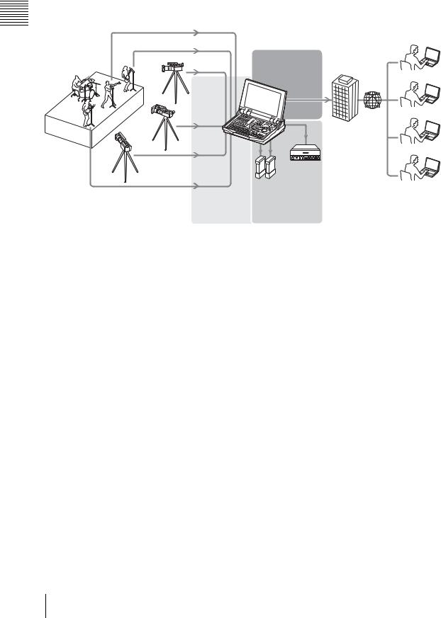
The Anycast Station Live Content Producer AWS-G500 is an audiovisual production system including camera control, video switching, and a live distribution system for the Internet.
The following are the principal features.
Chapter 1
Image keyed in |
Logo |
||
|
|
|
|
|
|
|
|
|
|
|
|
|
|
|
|
Superimposed text (downstream key)
Overview 1 Chapter
All-in-One
AWS-G500 is light and conveniently portable, while combining video switching and audio mixing functions with video monitor and camera control, to provide an inclusive package for live content generation. Whereas previously it was necessary to assemble various devices, this is no longer necessary, and the time and effort required to install, connect, and adjust the equipment has been greatly reduced.
Video Switching
•You can switch among up to six video inputs: analog, DV, SDI (when using a serial digital interface module), and RGB.
•The system provides both mix (dissolve) and wipe transition effects, Picture-in-Picture for combining videos, and luminance keying functions.
•Before carrying out a switching operation, you can preview the next selected image in the PVW viewer.
•You can mix video using a maximum of five effects at one time, such as incorporating (keying) a separate video clip when switching between two video clips with a wipe or other transition effect, as well as superimposing text (downstream key) and displaying a copyright logo.
Text Typing Tool Software
The system includes installed text typing tool software, which allows easy creation of titles. Titles created with the text typing tool software can be used in the DSK (downstream key) or as luminance keys.
Audio Mixing
You can mix up to six audio inputs. Each channel is provided with a range of
functions, including fader, input trim, filter equalizer, limiter, and compressor pan (balance), allowing the sound quality and level to be adjusted on each channel separately.
In addition, each channel has a prefader listen function, allowing you to monitor the input audio before any effects are applied by the fader, and each output has a delay function to correct any discrepancies between the audio and video timing.
Remote Camera Control
•Using a camera with VISCA support, you can remotely control the camera movements, including panning, tilting, and zoom.
•The camera preset function allows you to store camera pan, tilt, and zoom settings. Using the camera preset function, you can immediately set the camera to the preset state when required just by pressing a button.
Features of This System |
11 |
|
|
|
|

Overview 1 Chapter
External Recording Material on an External Hard Disk
You can record (.avi) video material (video and audio) being input to the unit to an external hard disk connected to the i.LINK connector. By connecting the external hard disk containing the recorded material to a nonlinear editing system, you can go straight into editing operations, without the need to transfer data from video tape to the nonlinear editing system.
You can also play files recorded on the external hard disk as input source material.
This system can use two external hard disks as standard, or three with the addition of an option module, recording four channels (maximum six channels) simultaneously.
Streaming Broadcast
You can encode in Real Media streaming file format (.rm) in real time, for a live broadcast.
12 Features of This System

Example Applications
The following are examples of applications utilizing the functions of AWS-
G500.
Event and presentation support
At seminars, events, and presentations you can use this unit to switch among camera inputs and data from a computer, while displaying the output on a projector or large monitor.
Principal functions used: video switching (such as cut switching or picture-in- picture), audio mixing, RGB input/output
RGB input
Switching , (page 65)
Recording
, (page 142)
Video output , (page 162)
External hard |
VTR |
|
|
RGB output disk |
|
Internet live broadcast
This unit includes a streaming server function. For broadcast to small audiences (about 20 people) over an intranet, this unit can be used as the streaming server without requiring an external server.
Principal functions used: video switching (such as a wipe transition), audio mixing, streaming encode, streaming server
Streaming settings/ broadcast
, (page 185)
Overview 1 Chapter
|
External |
VTR |
Switching |
hard disk |
|
, (page 65) |
Recording |
|
|
, (page 142) |
|
Example Applications |
13 |
|
|
|
|
Overview 1 Chapter
For the broadcast of things like live events to large audiences, you can broadcast via a streaming server (Helix server).
Principal functions used: video switching (such as a mix transition), audio mixing, streaming encode, camera presets.
Streaming
, (page 185)
Broadcast
Internet provider
|
VTR |
|
External |
|
hard disk |
Switching |
Recording |
, (page 65) |
, (page 142) |
14 Example Applications
Names and Functions of Parts
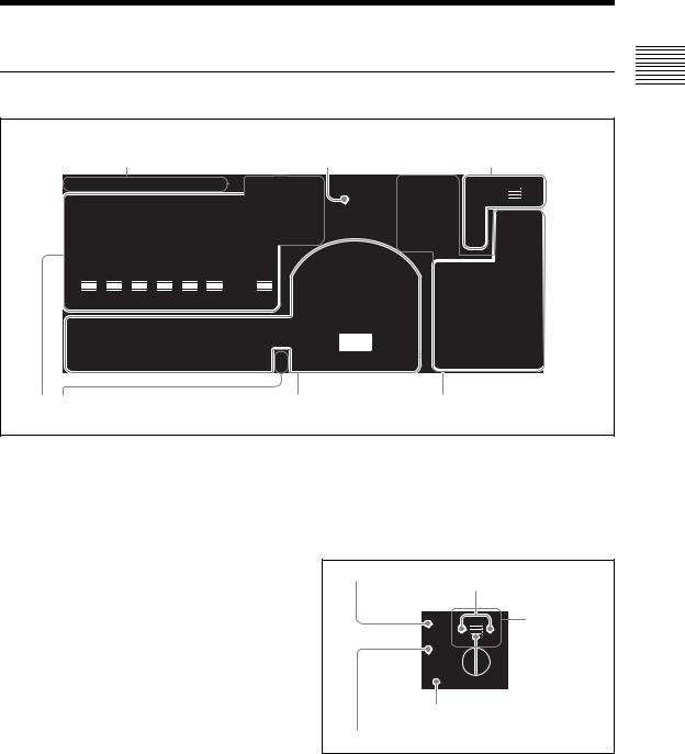
Front Panel
1 ACCESS buttons |
2 ON LINE button |
|
1 Menu control section |
ACCESS/ |
|
|
|
PFL |
|
|
ENTER |
AUDIO MONITOR |
7 |
8 |
9 |
CH ON |
ON LINE |
|
|
|
|
|
|
|
|
|
|
0 |
10 |
|
|
4 |
5 |
6 |
ESC |
|
|
|
|
|
|
|
|
|
|
|
|
|
|
||
|
|
|
|
|
|
|
|
MONI LEVEL |
|
|
|
|
|
|
|
+10 |
|
|
|
|
|
+10 |
+10 |
|
|
|
|
1 |
2 |
3 |
|
+5 |
|
|
|
|
|
+5 |
+5 |
DIM |
TB |
|
|
|
|
|
MENU |
0 |
|
|
|
|
|
0 |
0 |
|
|
|
|
|
X-Y |
||
|
|
|
|
|
|
|
|
|
0 |
|
|
||||
-5 |
|
|
|
|
|
-5 |
-5 |
|
|
|
|
|
|
|
|
-10 |
|
|
|
|
|
-10 |
-10 |
|
|
E |
F |
|
|
|
|
-20 |
|
|
|
|
|
-20 |
-20 |
|
IX |
F ECT |
PV |
|
|
REC |
|
|
|
|
|
|
|
M |
|
|
W |
|
|
||||
-30 |
|
|
|
|
|
-30 |
-30 |
|
|
|
|
|
|
|
|
-40 |
|
|
|
|
|
-40 |
-40 |
|
|
|
|
|
|
|
SHIFT |
-60 |
|
|
|
|
|
-60 |
-60 |
|
|
|
|
|
|
|
|
- |
|
|
|
|
|
- |
- |
|
|
|
|
|
|
|
|
|
|
|
|
|
|
|
|
|
KEY |
|
|
FTB |
|
|
|
|
|
|
|
|
|
|
|
|
|
|
|
|
|
|
|
1 |
2 |
3 |
4 |
5 |
6 |
|
|
PGM |
|
|
|
|
|
|
|
|
|
|
|
|
|
|
|
PGM |
CUT |
|
|
|
|
|
|
|
|
|
|
|
|
|
|
|
|
|
|
|
|
|
|
|
|
|
|
|
|
|
|
NEXT |
AUTO |
|
|
DSK |
|
|
|
|
|
|
|
|
|
|
|
|
TRANS |
|
|
|
|
|
|
1 |
2 |
3 |
4 |
5 |
6 |
INT |
|
MIC |
|
|
|
|
|
|
JOG/SHUTTLE |
2 Audio operation section |
3 Video switcher section |
4 Device control section |
(see page 16) |
(see page 17) |
(see page 18) |
a ACCESS buttons
These buttons display the ACCESS menu (page 30), and for audio monitoring (page 159). When you press an ACCESS button in one of columns 1 to 6, the ACCESS menu appears allowing adjustment of the related video and audio settings. If you hold down the ACCESS button in one of columns 1 to 6 for 0.5 seconds or more, you can monitor the audio assigned to the channel fader in the same column, and display the audio level meter for that channel only.
By holding down two or more ACCESS buttons simultaneously, you can monitor multiple audio channels.
b ON LINE button
This button starts and stops streaming broadcast (page 195).
1 Menu control block
Use these controls to access the menus and settings.
For details of operations, see “Menu Operations” (page 30).
1 ENTER button
Arrow buttons
4 Jog roller
ENTER
MENU
Roller
3 MENU button
2 ESC button
a ENTER button
This button confirms an item or input value in menu operations.
b ESC button
This button closes the current menu. In alphanumeric input mode, it cancels, and returns one level up the menu tree.
Overview 1 Chapter
Names and Functions of Parts |
15 |
|
|
|
|
Overview 1 Chapter
c MENU button |
d Jog roller |
This toggles the top menu on or off. |
Turn the roller up and down to select a menu item. |
|
Pressing the roller like a button has the same effect |
|
as pressing the ENTER button. |
|
Use the arrow buttons when a menu operation |
|
requires movement to left or right. |
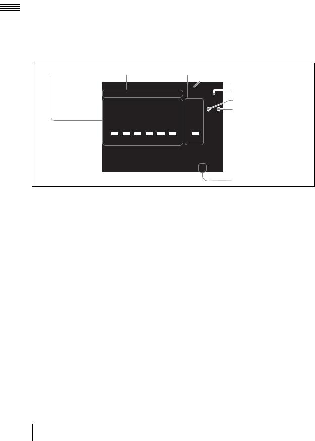
2 Audio operation section
Use these controls for audio settings and operations.
1 Audio channel faders |
2 CH ON buttons |
3 PGM fader |
CH ON
+10 |
+10 |
+10 |
+5 |
+5 |
+5 |
0 |
0 |
0 |
-5 |
-5 |
-5 |
-10 |
-10 |
-10 |
-20 |
-20 |
-20 |
-30 |
-30 |
-30 |
-40 |
-40 |
-40 |
-60 |
-60 |
-60 |
- |
- |
- |
1 2 3 4 5 6 PGM
MIC
0 10
MONI LEVEL
DIM |
TB |
4 AUDIO MONITOR button
5 Monitor level adjustment knob
6 DIM button
7 TB button
8 Microphone
a Audio channel faders
These buttons adjust the input levels of the audio assigned to channels 1 to 6, in the range from –∞ to +10 dB (page 141).
For details of audio signal assignment, see “Audio Signal Related Settings” (page 59).
b CH ON buttons
These buttons select whether the audio channels 1 to 6 are enabled or disabled.
Pressing a button enables the audio assigned to the corresponding audio channel. Channels for which the button is off are disabled (page 141).
c PGM fader
This button adjusts the overall audio output level of the program output, in the range from –∞ to +10 dB (page 141).
e Monitor level adjustment knob
This button adjusts the level of the monitor output and the output from the internal speakers and from the headphones (page 158).
f DIM button
This button enables the “audio attenuate” function. This reduces each of the level of the monitor output and the output from the internal speakers and from the headphones by 20 dB.
g TB button
This button lets you to speak while communicating on an external intercom system. While the TB button is lit, sound from the front panel microphone and headset microphone is output over the intercom system (page 155).
h Microphone
d AUDIO MONITOR button |
This button lets you speak on an external intercom |
This button switches the monitoring target. |
system. While the TB button is lit, sound from the |
Pressing if cycles the audio to be monitored |
microphone is output over the intercom system |
through the sequence PGM t AUX1 t AUX2 |
(page 155). |
t MIX t PGM (page 158). |
|
16 Names and Functions of Parts
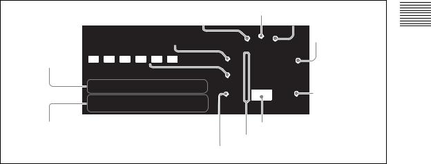
3 Video switcher section
This switches video.
|
6 EFFECT button |
5 MIX button |
7 PVW button |
4 KEY button |
|
8 FTB button |
E FF ECT |
P |
|
IX |
|
|
M |
|
VW |
1 PGM selection buttons |
3 CUT button |
|
KEY
FTB
CUT
PGM
9 DSK button
|
|
|
|
|
|
NEXT |
AUTO |
DSK |
|
|
|
|
|
|
|
TRANS |
|
1 |
2 |
3 |
4 |
5 |
6 |
INT |
MIC |
|
2 NEXT selection buttons |
|
|
|
|
|
0 Transition lever |
||
qa Indicators
qs AUTO TRANS button
a PGM selection buttons
These buttons select the video which will be displayed on the program output (page 66). Buttons 1 to 6 select the corresponding assigned video, and the INT button selects a video image generated internally by this unit (color matte, color bars, graphics files).
When you press one of these buttons, lighting it red, the video assigned to the button is sent to the program output.
For details of video assignment, see “Video Signal Related Settings” (page 57).
d KEY button
This button effectuates keying (pages 84). When this key lights green, the NEXT selection buttons, MIX button, AUTO TRANS button, CUT button, and transition lever are then assigned to keying.
e MIX button
This button effectuates a dissolve (gradually blending a new video into the existing image). When applying an effect it gradually blends in the effect (page 69).
f EFFECT button
b NEXT selection buttons
The NEXT selection buttons have the following functions.
•Selecting the video to be output on the program output after next switching transition (page 67)
•Selecting the video to be used for picture-in- picture (page 74)
•Selecting the video to be used when inserting a key in the program output (page 84)
•Specifying a camera to be controlled during camera control operations (page 133)
•Selecting the video for recording or playback (page 145, 147)
Buttons 1 to 6 select the corresponding assigned video, and the INT button selects a video image generated internally by this unit (color matte, color bars, graphics files).
c CUT button
This button instantaneously switches the video (page 65).
This button enables an effect other than dissolve in a transition or when applying an effect (page 70). You can also use it as a shortcut to the [Effect Pattern] menu.
g PVW button
With this button you can check the result of keying and picture-in-picture before switching it to program output, on the PVW viewer (page 88).
h FTB button
This button fades the video in from or out to a black screen (“fade-to-black”) (page 77).
i DSK button
This button add is used to images or text to the program output video (page 78). You can use it to superimpose text and so on.
j Transition lever
This lever allows you to manually execute a transition or effect (page 69).
Overview 1 Chapter
Names and Functions of Parts |
17 |
|
|
|
|

Overview 1 Chapter
k Indicators (Ff)
These indicators show the direction in which the transition lever is being moved. Moving the transition lever in the direction of the lit indicator starts the transition or effect.
However, supposing you press the AUTO TRANS button after moving the transition lever to the middle, for example, an inconsistency between the position of the fader and the application of the effect will arise and both indicators will light.
l AUTO TRANS button
This button carries out an automatic transition with a preset transition time, either from one video to another or when applying an effect (page 69).
4 Device control section
Use these controls for remote control of a camera with VISCA support connected to this system (page 132) or hard disk operations (material recording, file playback) (page 144, 147).
1 Numeric buttons 3 STOP button
|
|
|
4 REW button |
||
|
|
|
ENTER |
|
8 Positioner |
7 |
8 |
9 |
|
|
|
4 |
5 |
6 |
|
|
|
1 |
2 |
3 |
|
|
6 REC button |
|
|
|
|||
|
|
|
|
X-Y |
|
|
|
|
|
REC |
7 SHIFT |
|
|
|
|
SHIFT |
button |
FTB |
|
|
|
|
|
2 PLAY |
|
|
|
|
5 FFWD |
button |
|
|
|
|
button |
DSK |
|
|
|
|
9 Shuttle dial |
|
|
|
|
JOG/SHUTTLE |
|
0 Jog dial
a Numeric buttons
These buttons are used to save or recall a camera preset, or reset a camera (page 134, 138).
b PLAY button
This button plays back a file at normal speed. Hold down the REC button and press this button, to start recording on the hard disk (page 144).
c STOP button
This button stops file playback. Press shift and then press this button to switch the source viewer back from viewing a file on the hard disk to normal input (page 149).
During recording on the hard disk, hold down the REC button and press this button to stop recording (page 146).
d REW button
During file playback, play back fast in the reverse direction. Each time you press, the reverse speed increases (in six steps) (page 149).
e FFWD button
During file playback, play back fast in the forward direction. Each time you press, the playback speed increases (in six steps) (page 149).
f REC button
This button is used to start or stop the external hard disk recording (page 145).
REC + PLAY button |
Start hard disk recording |
|
|
REC + STOP button |
Stop hard disk recording |
|
|
g SHIFT button
This button is pressed while using other controls to perform the following operations.
SHIFT + jog dial |
Aperture (iris) adjustment on |
|
camera with VISCA support |
|
|
SHIFT + numeric |
Set camera presets |
button (1 to 6) |
|
|
|
SHIFT + numeric |
Camera reset |
button (0) |
|
|
|
SHIFT + REW button |
Skip to the beginning of a file |
|
|
SHIFT + FFWD |
Skip to the end of a file |
button |
|
|
|
SHIFT + STOP |
Close the file |
button |
|
|
|
h Positioner
This control is used to pan or tilt the camera. You can also control the speed of the camera by adjusting how hard you press this button (page 134).
You can also change the picture-in-picture and logo display positions (page 76, 83).
i Shuttle dial (outer ring)
This dial controls the camera zoom.
During file playback, turning this dial clockwise plays the file in the forward direction at a speed that corresponds to the amount the dial was turned (one of seven speeds) and turning this dial counterclockwise plays the file in the reverse direction at a speed that corresponds to the amount the dial was turned (one of seven speeds)
(page 134, 149).
18 Names and Functions of Parts
j Jog dial (inner dial)
This dial controls the camera focus and iris. During file playback, turning this dial plays the file at a slow speed that corresponds to the speed at which the dial is turned (page 134, 149).
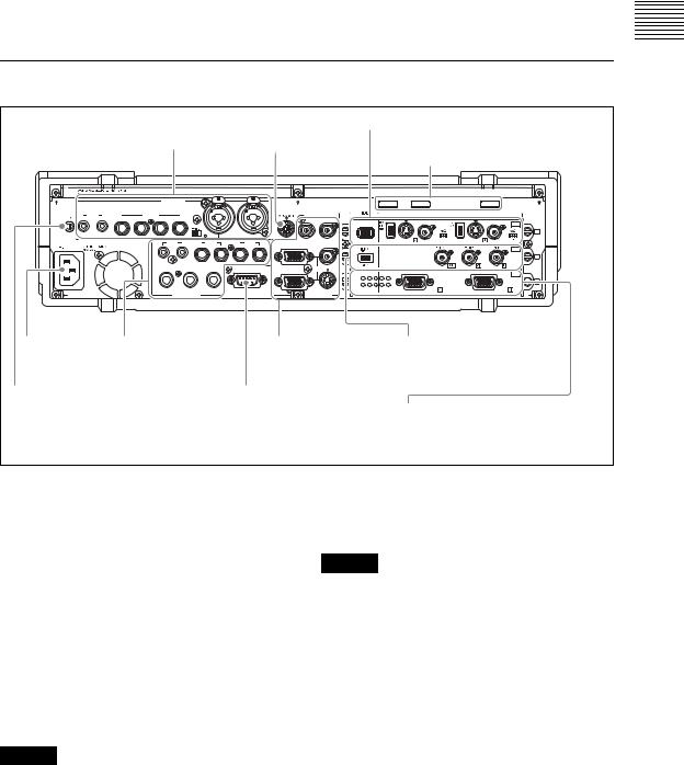
Rear Panel
|
|
|
|
|
|
|
|
|
|
4 SD video interface module |
|||
|
|
|
|
|
1 Audio inputs |
1VISCA |
|
(see page 21) |
|
|
|||
|
|
|
|
|
|
|
|
|
|||||
|
|
|
|
|
|
|
|
|
connector |
2 Cable clips |
|
||
|
|
|
|
|
AUDIO IN |
PUSH |
MIC/LINE |
PUSH |
|
|
|
|
|
|
|
|
|
|
|
2 |
1 |
|
|
|
VIDEO IN |
|
|
|
LINE |
|
|
MIC/LINE |
|
|
|
|
|
|
|
|
|
|
|
|
|
|
|
|
|
|
|
|
|
||
8 |
7 |
6 |
5 |
4 |
3 |
|
|
|
|
|
S VIDEO COMPOSITE |
S VIDEO COMPOSITE |
SD |
|
|
|
|
|
|
|
|
|
|
I.LINK |
|||
|
|
|
|
|
OFF |
ON |
|
|
|
|
OFF ON |
OFF |
1 |
|
|
|
|
|
|
|
|
|
|
|
ON |
||
|
|
|
|
|
MIX L |
2 AUX 1 |
R PGML |
|
S400 |
|
|
|
|
AC IN |
|
|
|
R |
RGB |
COMPOSITE |
|
|
SDI |
||||
|
|
|
|
|
|
|
|
|
|
|
|
||
2
HEADPHONES |
MONI |
INTERCOM |
RGB |
PGM S VIDEO |
|
|
|
R |
|
L |
|
|
RGB |
RGB |
PC |
|
|
5 |
1 |
|
|
|
|
|
|
|
|
|
|
||
|
|
9 |
6 |
|
|
|
3 |
AUDIO OUT |
VIOEO OUT |
4 Power supply |
2 Audio outputs |
3 Video outputs |
5 Serial digital interface |
connector |
(see page 20) |
(see page 21) |
module (option) |
(~AC IN) |
|
|
(see page 22) |
5 Ground terminal |
|
3 Intercom interface connector |
|
6 PC video interface module
* This figure is when an optional serial digital interface module (BKAW-580) |
(see page 22) |
|
is installed in slot 2 of the AWS-G500. An SD interface module is installed |
||
|
||
in slot 2 of the AWS-G500 at the time of shipment. |
|
a VISCA connector
To connect the chain of cameras with VISCA support to this unit for remote control operation, connect the VISCA cable (page 50).
b Cable clips
Use these clips to prevent cables from accidentally disconnecting (page 54).
c Intercom interface connector
Connect an external intercom system (page 155).
d Power supply connector (~AC IN)
Use to connect to an AC outlet (page 41).
Caution
When using a DC-AC inverter, the use of a 50 Hz (±3%) or 60 Hz (±3%) sine wave is recommended. Do not use a general-purpose inverter with a square output waveform.
e Ground terminal
When using this unit, connect the ground terminal to a grounding lead.
Caution
The ground terminal is close to the audio input connectors, so when connecting the grounding lead be careful not to touch the audio input connectors.
Overview 1 Chapter
Names and Functions of Parts |
19 |
|
|
|
|

Overview 1 Chapter
1 Audio inputs
1 Microphone/line input connectors |
|
|
||||||
|
(MIC/LINE) 1/2 |
|
|
|
|
|||
|
|
|
|
|
AUDIO IN |
PUSH |
MIC/LINE |
PUSH |
|
|
|
|
|
|
|
|
|
|
|
|
|
|
2 |
|
1 |
|
|
LINE |
|
|
MIC/LINE |
|
|
|
|
8 |
7 |
6 |
5 |
4 |
3 |
|
|
|
|
|
|
|
|
+45V |
|
|
|
|
|
|
|
|
OFF |
ON |
|
|
|
|
|
|
|
|
2 +48V switch |
||
|
|
3 Microphone/line input connectors |
||||||
|
|
|
(MIC/LINE) 3/4/5/6 |
|
|
|||
4 Line input connectors (LINE) 7/8 |
|
|
||||||
aMicrophone/line input connectors (MIC/ LINE) 1/2 (XLR 3-pin, TRS shared
balanced type)
Input an analog audio signal from a microphone or audio device.
b +48V switch
Use this switch when a capacitor microphone requiring a power supply is connected to the microphone/line input connectors (MIC/LINE) 1/ 2. When this is in the ON position, +48V is supplied.
c Microphone/line input connectors (MIC/
LINE) 3/4/5/6 (TRS balanced type)
Input an analog audio signal from a dynamic microphone or audio device.
d Line input connectors (LINE) 7/8 (RCA)
Input an analog audio signal from an audio device.
2 Audio outputs
1 MIX output connector 2 AUX output connector
(MIX) |
|
(AUX) 1/2 |
R MIX L |
2 |
AUX 1 R PGML |
HEADPHONES R |
MONI |
L |
|
|
3 PGM audio output |
AUDIO OUT |
connectors (PGM) |
|
5 Headphone connector |
4 Monitor output |
|
(HEADPHONES) |
|
connectors (MONI) |
a MIX output connector (MIX) L/R (RCA)
These connect to an external acoustic device to output audio signals (page 157).
b AUX output connector (AUX) 1/2 (TRS, balanced)
These connect to an external acoustic device to output audio signals. The output level can be adjusted (page 156).
c PGM audio output connectors (PGM) L/
R (TRS, balanced)
These output the final audio (program audio) created by this unit (page 156).
d Monitor output connectors (MONI) L/R
(RCA)
These provide monitor outputs of any of the PGM/ AUX1/AUX2/MIX audio (page 158).
e Headphone connector (HEADPHONES)
(standard phone jack)
This outputs one of the PGM/AUX1/AUX2/MIX audio (page 157).
The output level can be adjusted with the front panel monitor level adjustment knob (MONI LEVEL) (page 158).
20 Names and Functions of Parts
3Video outputs
1 Reference output connectors (REF OUT)
|
REF OUT |
|
RGB |
COMPOSITE |
|
RGB |
PGM S VIDEO |
|
|
VIOEO OUT |
2 PGM video output |
|
connectors (PGM) |
|
|
|
a Reference output connectors (REF OUT)
× 2
These output either a 59.94 Hz (NTSC) or 50 Hz (PAL) black burst signal to match the program output signal.
b PGM video output connectors (PGM)
•Composite video output connector (COMPOSITE) (BNC) × 1
•S-video output connector (S VIDEO) (S connector) × 1
These output the final program (PGM) video. You can switch to NTSC or PAL (page 59).
•RGB output connectors (RGB) (D-sub 15-pin) × 2
These output the final program (PGM) video as analog RGB signals and video RGB signals. Connect a projector or external display.
The following signals can be output (page 59).
-XGA (1,024 × 768) 60 Hz/75 Hz
-SXGA (1,280 × 1,024) 60 Hz
-15k RGB 50 Hz/59.94 Hz
4SD video interface module (BKAW-570)
1 Analog video input connectors
I.LINK |
S VIDEO COMPOSITE |
|
S VIDEO COMPOSITE |
SD |
|
OFF |
ON |
OFF |
ON |
S400 |
|
|
|
|
3 DV connectors 2 75-Ω termination (DV IN/ switch
DV PGM OUT)
4 i.Link connector (HDD)
a Analog video input connectors
Composite video input connectors (COMPOSITE) (BNC) × 2
S-video input connectors (S connector) × 2
Input analog video signals.
b 75-Ω termination switch
Set this switch to the OFF position when using a loop-through connection for a video monitor or the like by connecting a branch connector to the composite video input connector (COMPOSITE).
Note
The factory default setting is ON.
Use the end of a sharp implement such as a pen to operate the switch.
c DV connectors (DV IN/DV PGM OUT) (i.LINK 6-pin) × 2
Input and output digital video audio signals.
Notes
•Only one of the Composite/S Video/DV inputs can be used for each of IN1and IN2.
•If the DV connector is set as the output, material cannot be recorded from composite and S-video connectors (page 143).
d i.LINK connector (HDD) (i.LINK 6-pin)
× 1
When a hard disk drive is connected, video input to the same module and audio with the same source number as the video can be recorded in combination (page 144).
Overview 1 Chapter
Names and Functions of Parts |
21 |
|
|
|
|

Overview 1 Chapter
5Serial digital interface module (BKAW-580) (Option)
1SDI input connectors (SDI IN)
2PGM SDI output connector (SDI OUT)
3i.LINK connector (HDD)
a SDI input connectors (SDI IN) (BNC) × 2
Inputs SDI signals.
b PGM SDI output connector (SDI OUT)
(BNC) × 1
Outputs final video and audio (program video + audio) as SDI signals (page 143).
c i.LINK connector (HDD) (i.LINK 6 pins)
× 1
If an external hard disk is connected, you can record together both the video and the audio, which is assigned the same source number as the video, being input to the same module (page 144).
6PC video interface module (BKAW-550)
RGB |
RGB |
PC |
|
RGB input connectors |
|
|
(RGB) |
|
RGB input connectors (RGB) (D-sub 15pin) × 2
Input analog RGB signals from a computer or other source. The following image size and frequency combinations are supported.
•XGA (1,024 × 768) 60 Hz 75 Hz
•SXGA (1,280 × 1,024) 60 Hz
22 Names and Functions of Parts
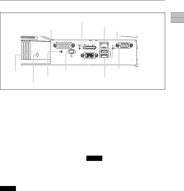
Side Panel
With the protective panel opened
2 “Memory Stick” slot
3 NETWORK connector
1 FACTORY USE |
4 REMOTE (remote control) |
|
connector |
||
connector |
||
|
FACTORY USE |
REMOTE |
||
|
|
NETWORK |
|
8 |
1 |
5 |
1 |
15 |
9 |
9 |
6 |
|
|
RGB(GUI) |
|
|
|
USB |
|
RESET |
|
|
|
|
|
|
|
|
|
|
|
|
|
|
|
|
|
|
|
|
|
|
|
|
|
|
|
|
|
|
|
|
|
|
|
|
|
|
|
|
|
|
|
|
|
|
|
|
qaVentilation |
8 |
1 |
(power) |
|
5Internal hard disk |
|||||||||
|
access indicator |
|||||||||||||
holes |
|
|
|
|
|
button |
|
|||||||
|
|
|
|
|
|
6 USB connectors |
||||||||
|
9 RESET button |
|
|
|||||||||||
|
0 Hole for anti-theft wire |
|
|
|
|
|
|
|
|
|
||||
|
|
|
7 Operating monitor connector (RGB (GUI)) |
|||||||||||
a FACTORY USE connector
Output a tally signal. Connecting this connector and the tally connector of a CCU (camera control unit) or other device enables the tally lamp of the camera to light (page 139).
b “Memory Stick” slot
This slot takes a “Memory Stick.” Use it for upgrading the operating software (page 200), importing font files (page 129), exporting/ importing job data (page 173 and 174), importing graphics files (page 175), etc.
While the “Memory Stick” is being accessed, the access indicator to the left of the slot lights.
c NETWORK connector (RJ-45)
Connect an external network adaptor or router. This supports 10Base-T and 100Base-TX Ethernet.
The green indicator blinks while the network is active.
An amber LED lights while the unit is connected by 100Base-TX.
Caution
When making Network connections
For safety, do not connect the Network connector to circuits which may be subjected to excessive voltage.
d REMOTE (remote control) connector
This connector is provided for future functional expansion.
e Internal hard disk access indicator
This indicator lights while the internal hard disk is being accessed.
f USB connectors (USB) (USB compatible)
The upper connector is number 1, and the lower connector is number 2.
Use these connectors to connect a USB keyboard. Also use them for connecting USB flash memory, upgrading the operating software (page 200), importing font files (page 129), exporting/ importing job data (page 173 and 174), importing graphics files (page 175), etc.
For details of the keyboards that can be used, consult your dealer or your Sony service representative.
When using the text typing tool software, you can connect and use a USB mouse.
Caution
•These do not support input from a USB camera.
•A USB mouse cannot be used with the main software.
g Operating monitor connector (RGB
(GUI)) (D-Sub 15-pin)
This connector outputs the operation screen to an external display at WXGA (1,280 × 800) size, at 60 Hz.
For information on which devices can be used, consult your dealer or your Sony service representative.
h 1 (power) button
This button powers the unit on or off. If you hold down the power button for at least 4 seconds, this forces a shutdown.
After a forced shutdown, the settings of the unit may not be preserved.
i RESET button
This button is provided for future functional expansion.
Overview 1 Chapter
Names and Functions of Parts |
23 |
|
|
|
|
Overview 1 Chapter
j Hole for anti-theft wire
This hole accepts a standard anti-theft wire (3 mm × 7 mm).
k Ventilation holes
Caution
Be careful not to obstruct the ventilation holes. If the ventilation holes are obstructed, the unit may overheat, leading to fire or breakdown.
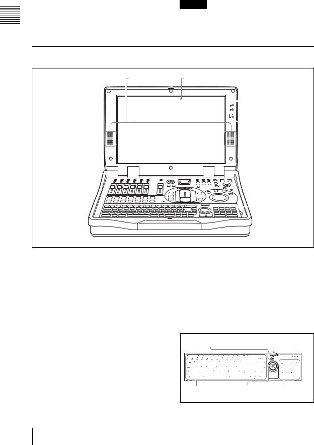
Other Parts
1 Built-in speakers |
2 Display |
 3 Num Lock indicator
 4 Caps Lock indicator
 5 Infrared receptor
 6 Keyboard
a Built-in speakers
You can monitor the audio using these speakers. There is no output from the built-in speakers when a headphone is connected to the headphone connector.
b Display
This shows the operation screen (page 25).
c Num Lock indicator
This lights green when the unit is in Num Lock mode.
d Caps Lock indicator
This lights green when the unit is in Caps Lock mode.
e Infrared receptor
This accepts signals from the keyboard supplied with this unit (page 44).
f Keyboard
Use this for text and numeric input. You can also use the keyboard for menu operations (page 31).
While the keyboard is mounted to the unit, the EXT POWER indicator on the keyboard lights green.
When using Esc and the F1 to F12 keys, hold down the Fn key and press the required key in the topmost row.
EXT POWER indicator |
Infrared receptor |
Character input keys Pointer |
Numeric |
|
keys |
For details on changing the keyboard language, see “Selecting the Keyboard Language” (page 46).
24 Names and Functions of Parts
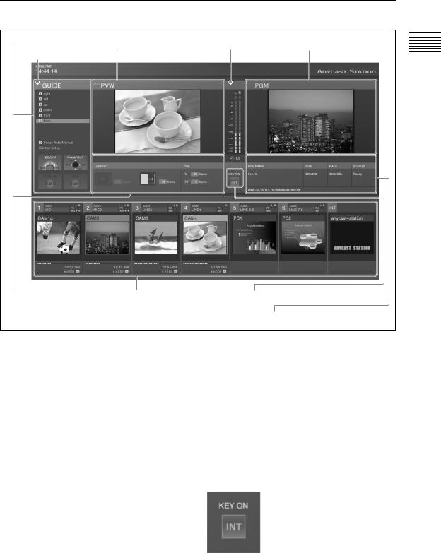
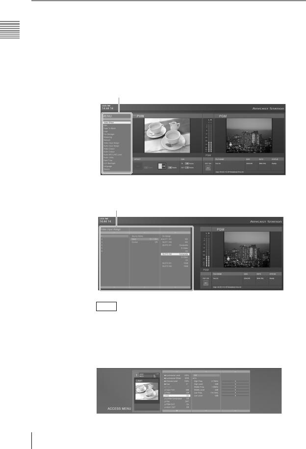
Operation Screen
1 Menu display |
2 PVW viewer |
3 Audio level meter 1 PGW viewer |
|
||
2 Guidance object indication |
|
|
5 Effect display 4 Source viewer 4 KEY ON
* This example screen shows the streaming settings displayed. |
3 Streaming display |
|
Normally the streaming display cannot be viewed. |
||
|
a Menu display
This displays the top menus (page 30), the INT material selection menu (pages 79, 161), the camera guide menu (pages 133, 134), and the HDD guide menu (page 147).
b Guidance object indication
The color of the guidance object indication has the following significance.
Amber:when a video subject to camera control (page 132) and external hard disk control (page 144) or INT is selected with the NEXT selection buttons (while the KEY button is not lit).
Green:when a video subject to camera control and external hard disk control or INT is specified with the NEXT selection buttons (while the KEY button is lit).
Off:when other than a video subject to camera control and external hard disk control or INT is specified with the NEXT selection buttons.
c Audio level meter
When monitoring the any of the PGM/AUX1/ AUX2/MIX audio outputs or Pre Fader Listen (PFL) result, this shows the audio level. An indication below the meter shows which of PGM/ AUX1/AUX2/MIX or PFL is being monitored. When the level exceeds the meter range, the uppermost indicator lights red (page 158).
d KEY ON
The indicator lights red during keying to program output video. The number (1 to 6) or “INT” of the source selected for keying appears.
Overview 1 Chapter
Names and Functions of Parts |
25 |
|
|
|
|
Overview 1 Chapter
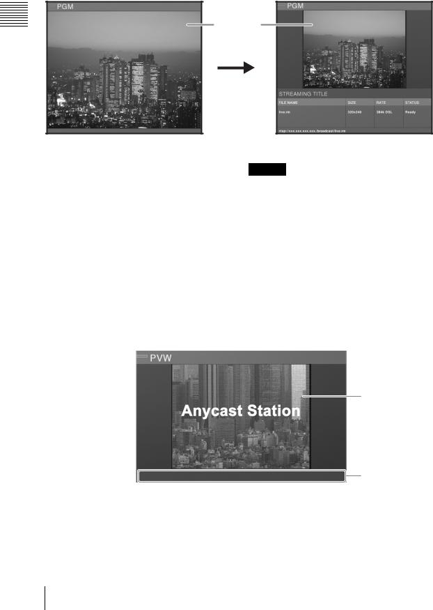
1 PGM viewer
This shows a program output.
Program
video
Normal |
When configuring streaming settings |
Program video
The program output video is shown at 480 × 360 pixels, 30 fps (25 fps for PAL). During streaming, the size is 320 × 240 pixels.
Caution
•Video displayed on the PGM viewer lags several frames behind the video output from the PGM video output connectors.
•In any of the video viewers displayed on the operation screen (PGM/PVW/source) the video may deteriorate, but this is an artifact of the display system. There is no effect on the video output from the program video output connectors.
2 PVW viewer
This shows a preview of the video.
This allows you to check the input video selected to be shown next, keying, or picture-in-picture result before switching to program output.
1What the preview  is showing
2 Preview video
3 Status
a What the preview is showing
Amber: when showing the video selected by the NEXT selection button.
Green: when showing the video selected by the NEXT selection button when the KEY button is lit (video with a key inserted).
b Preview video
Normally the video selected with the NEXT selection buttons is shown at 320 × 240 pixels, 15 fps (12 to 13 fps for PAL).
26 Names and Functions of Parts
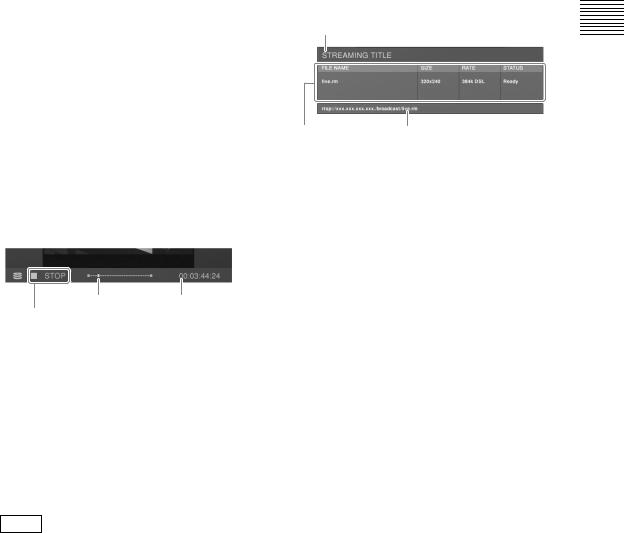
c Status
The status shown here differs as follows depending on the video to be previewed.
When showing video from a remotely controlled VISCA compliant camera
The status of the VISCA compliant camera is shown.
No Response:communication cannot be established with the camera.
Initializing:appears at system startup and during camera reset.
When showing an INT graphics file
Loading:while file is loading
When playing a file on an external hard disk
The status of file operations is shown.
Play position |
Timecode |
File operation
File operation indications
Opening: while opening a file  PLAY: during playback
  STOP: when stopped
 STILL: when playback speed is set to zero with the shuttle dial or playback is stopped with the jog dial.
JOG: while using the jog dial.
 x2: fast forward (x2, x4, x8, x16, x32, x64)
  x2: fast reverse (x2, x4, x8, x16, x32, x64)
Note
The x1/8, x1/2, and x1 indications are also displayed while you are using the shuttle dial for playback operations.
Play position
This shows the file play position.
When the play position is at the beginning or end, z of each end lights.
An icon appears on the right while auto repeat playback is set (page 150).
3 Streaming display
This shows the settings and status of the streaming broadcast.
1 Title
3 Information display 2 Access URL
a Title
This shows the streaming title.
b Access URL
This appears when the unit is used as a server for a broadcast. Audience members can view the broadcast by accessing this URL.
c Information display
This shows the following information: FILE NAME: the file name of the broadcast SIZE: video size set in the top menu RATE: transfer rate set in the top menu STATUS: the status of the server or encoder
Initializing |
Starting server or encoder |
|
|
Ready |
Server started up, and encoder |
|
ready |
|
|
Starting |
Encoder connecting to server |
|
|
Running |
Encoding |
|
|
Stopping |
Ending the encoder |
|
|
Reconnecting |
While re-establishing a |
|
connection to the server. |
|
|
Failed |
When a connection failed to be |
|
established because of the |
|
settings of the unit, the status of |
|
the network or external server, |
|
etc. |
|
|
Error |
The encoder had failed to end, or |
|
an error occurred. |
|
|
Overview 1 Chapter
Names and Functions of Parts |
27 |
|
|
|
|
Overview 1 Chapter
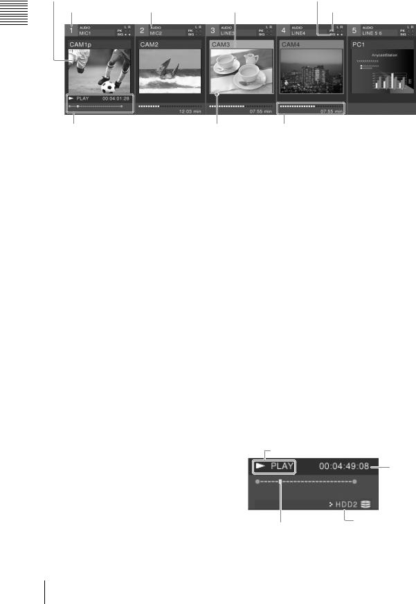
4 Source viewer
1 Thumbnails |
|
5 Input signal indication |
2 Source number |
3 Audio source name 4 Video source name |
6 Peak indication |
8 Device status |
7 Selection frame 9 Hard disk status |
a Thumbnails |
g Selection frame |
These show the video assigned to the selection buttons at 160 × 120 pixels, at 10 fps (8 to 9 fps for PAL).
b Source number
This is the number (1 to 6 and INT) assigned to the source (video or audio).
These correspond to the PGM selection button, the NEXT selection button, and the audio channel fader numbers.
c Audio source name
This shows the name of the audio signal assigned to the channel fader (page 59) or the file name on the external hard disk (page 147).
d Video source name
In viewers 1 to 6, this shows the name of the video signal assigned to the selection button (page 57) or the file name on the external hard disk (page 147). For the INT viewer, this displays the color matte and color bars, or the graphics file name selected in the INT source selection menu.
e Input signal indication
If the input level of the audio assigned to a channel fader is -60 dBFS or more, this lights green, and you can check that there is an audio input.
For stereo you can check left and right channels separately; for monaural both channels are shown the same.
f Peak indication
If the input level of the audio assigned to a channel fader is -8 dBFS or more, this lights red.
For stereo you can check left and right channels separately; for monaural both channels are shown the same.
Depending on the selection state, the frame color changes.
Red: video selected with PGM selection button Amber: video selected with NEXT selection
button
Green: video selected with NEXT selection button when the KEY button is lit (video with a key inserted)
h Device status
The content displayed differs as follows depending on the material.
Video from a VISCA-compatible camera being controlled remotely
Displays the VISCA-compatible camera’s status. No Response: communication cannot be
established with the camera.
Initializing: appears at system startup and during camera reset.
INT graphics file
Loading:while file is loading
When playing a file on the external hard disk
The status of file operation is shown.
File operation
Timecode
Play position |
Corresponding hard |
|
disk number |
||
|
28 Names and Functions of Parts
File operation indications
Opening: while opening a file  PLAY: during playback
  STOP: when stopped
 STILL: when playback speed is set to zero with the shuttle dial or playback is stopped with the jog dial.
JOG: while using the jog dial.
 x2: fast forward (x2, x4, x8, x16, x32, x64)
  x2: fast reverse (x2, x4, x8, x16, x32, x64)
Note
The x1/8, x1/2, and x1 indications are also displayed while you are using the shuttle dial for playback operations.
Play position
This shows the file play position.
When the play position is at the beginning or end, z of each end lights.
An icon appears on the right while auto repeat playback is set (page 150).
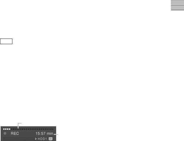
i Hard disk status
When an external hard disk is connected, this shows the status of the hard disk, the remaining recording capacity, and the recording status.
Remaining capacity shown by progress bar
Available recording time
 Hard disk drive number
Recording operations
 REC PAUSE: recording on standby
 REC: recording
Unformatted: error requiring formatting Disk Full: no disk space left (200 MB or less)
File Number Full: the number of files that can be recorded has been exceeded
Device Error: it became impossible to recognize the hard disk during recording
REC Error: recording error
5 Effect display
This shows video transition effect types and patterns, and transition time (page 72).
Overview 1 Chapter
Names and Functions of Parts |
29 |
|
|
|
|
Overview 1 Chapter
Menu Operations
This unit includes top menus, which are used to make various operational settings, and ACCESS menus, which are used to make adjustments to the video and audio being input to this unit.
This section describes the basic operations common to these menus.
Displaying top menus and ACCESS menus
Top menus
Press the MENU button, to display the top menu in the menu display.
Top menu
When you select and confirm an item in the top menu, submenus appear, three levels deep.
Sub-menu
Note
You can set priority to be given to displaying the PVW viewer while submenus are open (page 90).
ACCESS menu
Press the ACCESS button corresponding to the number of input you want to adjust, to display the ACCESS menus, three levels deep, in the source viewer together with the viewer for that number.
30 Names and Functions of Parts
Loading...