


7819901050

Operating Instructions
© 2004 Sony Corporation
2-586-675-11 (1)
7819901050
IT
JP
FR
DE
ES
IT
CS
DVD/CD
Rewritable Drive
DRU-720A

2
Safety Regulations
WARNING
You are cautioned that any changes or modifications not expressly approved in this manual
could void your authority to operate this equipment.
To prevent fire or shock hazard, do not expose the unit to rain or moisture.
To avoid electrical shock, do not open the cabinet. Refer servicing to qualified personnel only.
CAUTION:
As the laser beam in the DRU-720A is harmful to the eyes, do not attempt to disassemble the
cabinet. Refer servicing to qualified personnel only.
The use of optical instruments with this product will increase eye hazard.
The use of controls or adjustments or performance of procedures other than those specified
herein may result in hazardous radiation exposure.
This label is located on the top of the drive unit enclosure.
Dieses Etikett befindet sich auf der Oberseite des Laufwerksgehäuses.

3
The DRU-720A is classified as a CLASS 1 LASER PRODUCT.
The CLASS 1 LASER PRODUCT label is located at the top of the enclosure.
Bei diesem DRU-720A handelt es sich um ein Laser-Produkt der Klasse 1.
Das Etikett mit der Aufschrift LASER KLASSE 1 PRODUKT befindet sich auf der Oberseite
des Gehäses.
CE Sicherheitsbestimmungen
Diese Ausrüstung erfüllt die Europäischen EMC-Bestimmungen für die Verwendung in
folgender / folgenden Umgebung(en):
• Wohngegenden
• Gewerbegebiete
• Leichtindustriegebiete
(Diese Ausrüstung erfüllt die Bestimmungen der Norm EN55022, Klasse B.)
CLASS 1
LASER PRODUCT
LASER KLASSE 1
PRODUKT
LUOKAN 1 LASERLAITE
KLASS 1 LASER APPARAT

4
Table of Contents
Safety Regulations .......................... 2
Introduction
Unpacking the Package Contents ...6
Features ...........................................6
System Requirements .....................7
Part Names and Functions ..............8
Setup
Setting up the Drive ...................... 10
Appropriate Jumper Settings ........ 15
Replacing your current optical
drive with the DVD/CD rewritable
drive ............................................15
Installing the DVD/CD rewritable
drive as a second drive ...............16
Installing the DVD/CD rewritable
drive as a third drive ................... 17
Installing the DVD/CD rewritable
drive as a fourth drive ................18
Operation
Using the Drive .............................19
Supplied Software ......................19
Using Generic Software with the
Drive ...........................................20
Compatible Discs ..........................21
Recommended Writable Discs ...23
Writable Disc Features ...............24
Precautions when Writing Data to
Disc ...............................................27
Maximizing Performance .............29
User Support Web Site ...............29
Updating the Firmware ...............29
Turbo Boost Function .................29
Miscellaneous
Precautions for Use .......................30
Specifications ................................31
Support Overview .........................33
User Support Web Site ...............33
Update the Drive Firmware ........33
Product and Support
Information .................................33

5
• is a trademark of Sony Corporation.
• Pentium is a registrated trademark of Intel Corporation.
• Microsoft, MS, MS-DOS and Windows are registered trademarks of Microsoft Corporation.
• Other system and product names used herein are registered trademarks or trademarks of their
respective manufacturers, although the ™ and ® marks are not used in the text.
❑ Our product warranty is valid only when the supplied accessories (including software) are
used in the specified or recommended system environment, in accordance with the
documentation, and applies only to this DVD/CD rewritable drive. Our customer service
and user support apply only under these product warranty conditions.
❑ Please note that we cannot accept responsibility for failure of the computer or other
devices, incompatibility with special hardware, operating problems caused by improper
installation of software, loss of data, discs or other accidental or incidental damage that
might occur when using this product.
❑ The guarantee and user support for this product are valid only within the countries or sales
regions specified on the warranty card.
❑ Copyright laws prohibit the copying in part or in full of the supplied software and
documentation, or loaning the software, without obtaining permission of the copyright
holder.
❑ We cannot accept responsibility for any direct or indirect financial damage or loss of profit
that might occur when using the supplied software.
❑ The supplied software can only be used with this product.
❑ Specifications of the supplied software may be changed without notice in the interest of
product improvement.
Please Record Responsibly
Before copying anything onto a disc, please be sure that you are not violating copyright
laws. Most software companies allow you to make a backup or archive copy of software.
Check your software’s license agreement for details.
6
B Introduction
Unpacking the
Package Contents
Please verify that the package contains the
following when unpacking.
If any of these items appear to be missing
and/or damaged, please contact your dealer.
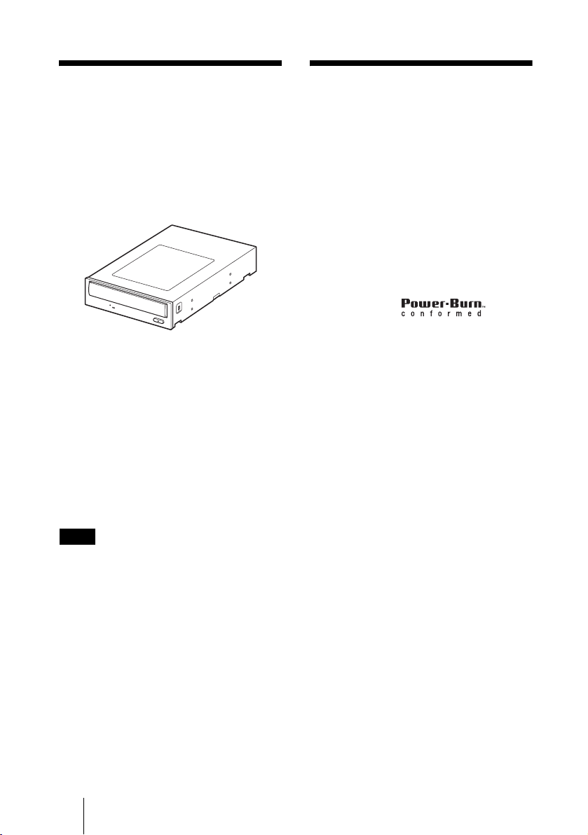
•Drive
• 40-pin ATAPI (IDE) flat cable
•Screws (×4)
• Quick start guide
• Software quick start guide
• Operating instructions
(this document)
• Front panel replacement guide
• Front panel replacement kit
• Software disc
• Warranty card
Note
Make sure that you back up the supplied software
disc on another disc because the software disc is
not distributed independently.
Features
This product offers the following features.
❑ An internal DVD/CD rewritable drive
with ATAPI (EIDE) interface for
computers.
❑ Can be used horizontally or vertically.
❑ The drive can write to DVD+R Double
Layer discs.
❑ You can write at a maximum of 16×
when using high speed DVD+R, DVD-
R discs.
❑ The drive can write to seven types of
disc.
❑ Features the
technology to prevent buffer underrun
errors.
❑ You can replace the front panel of the
drive with the supplied replacement
front panel.

7
Introduction
System
Requirements
The drive should be used with a system that
meets the following requirements
1)
.
❑ PC/AT-compatible computer
❑ CPU: Pentium III, 800 MHz or higher
(with Nero Vision Express: Pentium 4,
1.6 GHz recommended)
❑ 256 MB RAM or more
❑ 1 GB (with Nero Vision Express:
10 GB) free hard disk space
❑ One available EIDE (ATAPI) interface
connection with DMA capability
2)
❑ One empty 5-inch half-height drive bay
❑ One available internal +12 V/+5 V
power connector
3)
❑ Operating system:
Windows 2000 Professional
(referred to as Windows 2000),
Windows XP Home Edition or
Windows XP Professional
(referred to as Windows XP)
1)
The above requirements are the minimum
necessary requirements to write to disc
normally. Under actual operating conditions,
the requirements imposed by your software
must also be met. For details, refer to your
software documentation.
2)
The drive does not support connection to an
ATAPI interface card. Connect the drive to the
IDE (ATAPI) interface connector of your
computer’s motherboard.
3)
The drive consumes a lot of power when
operating at high speeds. You should therefore
make sure that the rated power output of the
power outlet where you connect all your drives
is sufficient to power all the drives, including
this one. For details about each drive’s power
consumption rating, refer to their
documentation.
8
Part Names and Functions
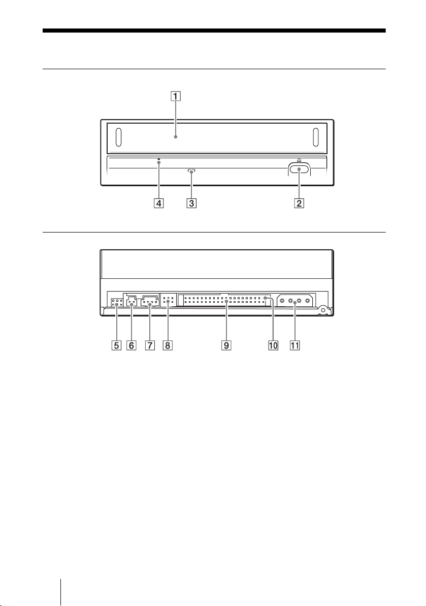
Front Panel
Rear Panel
9
Introduction
A Disc tray
Insert discs here, label side up.
Hint
When you insert a disc into the drive, make
sure that it is under the four pins. When using
the drive vertically, make sure that you set the
disc inside the two lower pins.
B Eject button
Press to open and close the disc tray.
C Busy indicator
Indicates the drive status.
Lit : The drive is reading data,
playing back an audio CD, or
writing packets.
Blinking: The drive is writing data
(disc-at-once, track-at-once),
formatting a disc, or
deleting
1)
data from a disc.
Off : The drive is in a state other
than those outlined above.
1)
Some drives indicate this state with the lit
indicator.
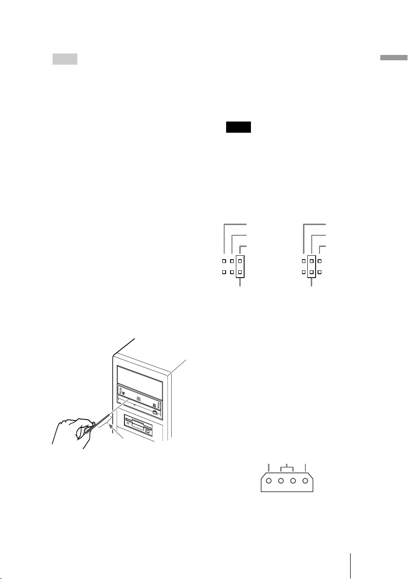
D Emergency eject hole
If you cannot open the disc tray with the
eject button, turn off your computer, and
then insert a thin, elongated object into
this hole to eject the disc tray manually.
E Do not use.
F Do not use.
G Analog audio connector
Analog stereo audio output. Using an
audio cable, connect to the audio
connector of a computer with a sound
card.
Note
Connecting a cable other than an audio
cable or otherwise misusing the audio
connector may cause damage to the
product.
H Jumper
A jumper is set on the appropriate pins
before connecting the drive.
I IDE connector
Connect to the computer with the
supplied IDE flat cable.
J Pin 1
The location of this pin determines the
proper orientation of the connection
cable.
K Power connector
Connect the connector of the computer’s
internal power supply.
About 40 mm (1.6 in)
CS EL
SLAVE
MASTER
CS EL
SLAVE
MASTER
Jumper pinsJumper pins
5V GND 12V
DC INPUT
10
B Setup
Setting up the Drive
The installation and setup procedures outlined below assume that you are using
a standard computer. For details about how to install peripheral devices into
your computer, refer to the instructions supplied with your computer.
Before installing the drive
Referring to “Unpacking the Package Contents” on page 6, verify that the
contents of the drive package are complete.
Note
Avoid touching any exposed electronic conductors or contacts on the circuit boards of the
drive or your computer, as they can be damaged by electrostatic discharges from your body.
Make sure that you discharge any static electricity from your body before performing this
operation.
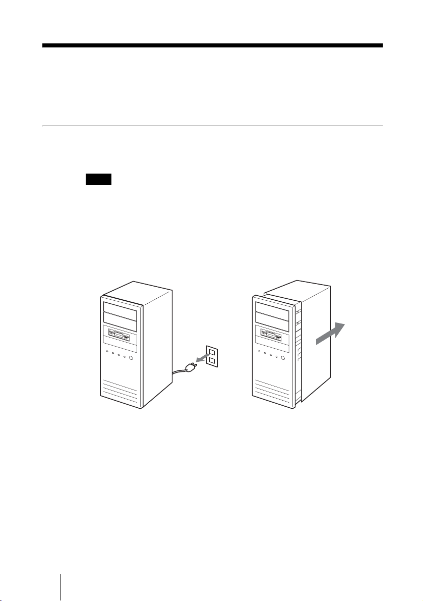
1 Turn off your computer, disconnect the power cable from the
outlet, and then remove the computer cover.
11
Setup
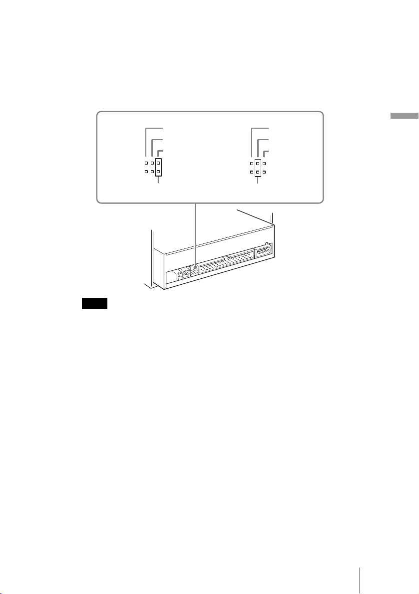
2 Determine which connection method you want to use, and then
adjust the jumper.
Depending on whether you want to connect the drive as MASTER or SLAVE,
place the jumper on the pins, as illustrated below.
If you are unsure of the appropriate jumper setting, see “Appropriate Jumper
Settings” on page 15.
Notes
• If installing the drive to replace one using the CSEL jumper setting, place the jumper on
the CSEL pins of the drive before installing it.
• Only place the jumper vertically, as illustrated. Placing the jumper horizontally may
damage the drive and/or cause malfunctions.
Jumper Jumper
SLAVE
CS EL
MASTER
SLAVE
CS EL
MASTER
 Loading...