


 Loading...
GM29
User Guide
Draft PA2
5.7.02

The product described in this document conforms to the Radio and Telecommunication Terminal Equipment (R&TTE) directive 99/5/EC with requirements covering EMC directive 89/336/EEC and Low Voltage directive 73/23/EEC. The product fulfils the requirements according to
3GPP TS 51.010-1, EN 301 489-7 and EN60950.
SAR statement: This product is intended to be used with the antenna or other radiating element at least 20cm away from any part of the human body.
The information contained in this document is the proprietary information of
Sony Ericsson Mobile Communications International. The contents are confidential and any disclosure to persons other than the officers, employees, agents or subcontractors of the owner or licensee of this document, without the prior written consent of Sony Ericsson Mobile Communications International, is strictly prohibited. Further, no portion of this publication may be reproduced, stored in a retrieval system, or transmitted in any form or by any means, electronic or mechanical, including photocopying and recording, without the prior written consent of Sony Ericsson Mobile Communications International, the copyright holder.
First edition (XXXX 2002)
Sony Ericsson Mobile Communications International publishes this document without making any warranty as to the content contained herein. Further
Sony Ericsson Mobile Communications International reserves the right to make modifications, additions and deletions to this document due to typographical errors, inaccurate information, or improvements to programs and/or equipment at any time and without notice. Such changes will, nevertheless be incorporated into new editions of this document.
All rights reserved.
© Sony Ericsson Mobile Communications International, 2002
Publication number: LZT 123 7360 PA1
Printed in UK
Contents
Introduction . . . . . . . . . . . . . . .4
Description. . . . . . . . . . . . . . . . . . . . . . . . 4
Highlights . . . . . . . . . . . . . . . . . . . . . . . . 4
Installation . . . . . . . . . . . . . . . .5
Safety and Installation
Information . . . . . . . . . . . . . . . . . . . . . . . 5
Securing the Modem . . . . . . . . . . . . . . . . 5
Electrical Connections . . . . . . .6
Power Connector . . . . . . . . . . . . . . . . . . . 6
Audio Connector . . . . . . . . . . . . . . . . . . . 7
Antenna Connector . . . . . . . . . . . . . . . . . 7
RS232 Serial Port . . . . . . . . . . . . . . . . . . 8
SIM Card Reader . . . . . . . . . . . . . . . . . . . 9
Operation . . . . . . . . . . . . . . . . 10
Switching On the Modem . . . . . . . . . . . 10
Switching Off the Modem . . . . . . . . . . . 10
Resetting the Modem. . . . . . . . . . . . . . . 10
Operating States/LED . . . . . . . . . . . . . . 10
Accessories . . . . . . . . . . . . . . 11
AT Commands . . . . . . . . . . . . 11
Type Approval . . . . . . . . . . . . 11
Software Updates . . . . . . . . . . 11
Certification . . . . . . . . . . . . . . 11
Troubleshooting . . . . . . . . . . . 11
Modem Not Working. . . . . . . . . . . . . . . 11
Software Crashed . . . . . . . . . . . . . . . . . . 11
No Communication,
Modem Switched On . . . . . . . . . . . . . . . 11
Service and Support . . . . . . . . 11
Technical Data . . . . . . . . . . . . 14
Data Features . . . . . . . . . . . . . . . . . . . . . 14 Short Message Service Features . . . . . . 14 Voice Features . . . . . . . . . . . . . . . . . . . . 14 Fax Features. . . . . . . . . . . . . . . . . . . . . . 14 Data Storage . . . . . . . . . . . . . . . . . . . . . 14 Power Supply . . . . . . . . . . . . . . . . . . . . . 15 Average Power Consumption . . . . . . . . 15 Radio Specifications . . . . . . . . . . . . . . . 15 Audio Specifications . . . . . . . . . . . . . . . 16 SIM Card Reader . . . . . . . . . . . . . . . . . . 16 Electrical Connectors and LED . . . . . . . 16 Mechanical Specification . . . . . . . . . . . 16 Environmental specifications . . . . . . . . 17 Certification . . . . . . . . . . . . . . . . . . . . . . 17
3

Introduction
Description
The dual band EGSM 900/1800 MHz GM29, is a GSM/GPRS serial modem. The modem is a powerful and flexible device that can be used in a wide range of telemetry and telematics applications that rely on the remote exchange of data, voice, SMS or faxes via the GSM cellular network.
Small and lightweight, the GM29 has standard connectors and an integral SIM card reader making it easy and quick to integrate. As well as providing a standard RS232 serial communication interface the GM29 also has an audio interface allowing an analogue handset to be connected. When the GM29 is integrated into an external application, a wireless communicaions system is created.
A typical end-to-end system consists of a micro controller in an external application communicating, via the GM29 modem, with a remote terminal or host using the GSM network. The micro controller uses a set of AT commands to control the modem, and to set up the end-to-end communications link, via its 9-way RS232 serial interface.
GM29 serial modems are intended to be used by manufacturers, system integrators, application developers and developers of a wide range of equipment and business solutions, typically in the following fields:
•Security and alarms
•Vending
•Monitoring and control
•Utilities
•Fleet Management
Simply connect the GM29 into your application as described later in this guide.
Highlights
•Dual band, EGSM 900/1800 MHz, GSM/GPRS serial modem
•Flexible plug-and-play device
•Data: GPRS, HSCSD, CSD, SMS
•Voice: full rate, enhanced full rate, half rate
•SMS: mobile-originated, mobileterminated, cell broadcast
•Fax: Group 3, Classes 1 & 2
•5 V to 32V d.c. input
•Standard connectors
•R&TTE type approved
View of Left Side
LED |
Antenna |
connector |
RS232 |
connector |
View of Right Side
Access to SIM card |
Power |
connector |
Handset |
connector |
Fixing hole |
4 Introduction
Installation
Safety and Installation
Information
[Needs to be checked and re-written]
•The Terminal should be installed and setup only by qualified personnel.
•Connect a fast 1.25A fuse to the incoming line for the positive supply voltage to protect the Terminal.
•If a power supply unit is used to supply the GM29 modem, it must meet the demands placed on SELV circuits in accordance with EN60950. When using batteries and accumulators, adhere to the relevant regulations.
•The maximum permissible connection length between the GM29 Modem and the supply source is 3m.
•Your supplier will be pleased to provide you with a detailed technical description and technical support for the GM29 Modem.
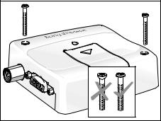
Securing the Modem
NOTE! Before securing the modem take into account the amount of additional space required for the mating connectors and cables that will be used in the application.
NOTE! Where access is restricted, it may be easier to connect all the cables to the modem prior to securing it in the application.
Securely attach the GM29 modem to the host application using two 3mm diameter pan-head screws of appropriate length as shown below.
CAUTION! Do not over tighten the fixings screws. Excessive torque applied to the screws can crack the plastic case.
Fixing Screws
Installation 5
Electrical Connections
All electrical connections to the GM29 are protected in compliance with the standard air (4 kV) and contact (8kV) discharge ESD tests, of EN 301 489-1.
The modem uses the following industry standard connectors:
•RJ11 6-way (power connector)
•RJ9 4-way (audio connector)
•SIM card reader
•FME male coaxial jack (antenna connector)
•Sub-D socket, 9 pin (RS232 serial port)
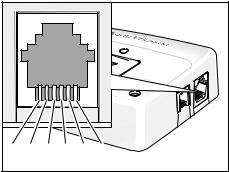
Power Connector
An RJ11 6-way connector, as shown and described below, serves as a means of supplying and controlling d.c. power to the modem.
Connect positive power to VCC (pin 1) and the ground or negative to GND (pin 6). VCC and GND are reverse polarity and overvoltage protected
NOTE! Application of the supply voltage VCC, does not automatically switch on the modem.
Switch on is usually achieved by use of the TO_IN signal, which can be supplied by the host application. Alternatively the modem can be switched on at the same time that power is applied by hard-wiring TO_IN to VCC. Refer to “Switching On the Modem” on page 10 for information on switch on methods.
Similarly the host application can be designed to switch off the GM29 or perform a hard reboot of the modem's software by use of the HR_IN signal. Refer to “Switching Off the Modem” and “Resetting the Modem” on page 10 for additional information.
TO_IN and HR_IN are referenced to GND.
RJ11 Power Connector
6 |
5 |
4 |
3 |
2 |
1 |
1 VCC |
3 HR_IN |
5 n/c |
|
2 n/c |
4 TO_IN |
6 GND |
|
|
|
|
|
Signal |
Description |
|
|
|
|
||
VCC |
Positive power input |
||
|
(5V to 32V d.c. at 1.5 Amax) |
||
TO_IN |
Active high control line used for |
||
|
switching on the modem |
||
|
(–0.5V to 32V; |
|
|
|
VIH > 5V, VIL < 2 V) |
|
|
|
|
||
HR_IN |
Active high control line used to |
||
|
switch off or reset the modem |
||
|
(–0.5V to 32V; |
|
|
|
VIH > 5V, VIL < 2 V) |
|
|
GND |
Negative power (ground) input |
||
|
and return path for TO_IN and |
||
|
HR_IN |
|
|
|
|
|
|
6 Electrical Connections
Loading...