


Soleus Air KFTHP-12-OD, KFTHP-18-ID, KFTHP-24-ID, 3119233, KFTHP-12-ID User Manual
...13 SEER Mini Split Air Conditioner
with Heat Pump and Back up Electric Heat Strip
KFTHP-12-ID/KFTHP-12-OD KFTHP-18-ID/KFTHP-18-OD KFTHP-24-ID/KFTHP-24-OD
ERT |
E |
|
T |
K |
|
I |
|
|
N |
|
|
|
|
CM |
C |
LI |
D |
US |
|
|
STE |
|
|
3119233 |
||
CAUTION |
|
All units must be installed by a licensed contractor or technician. |
|
Installation must be in accordance with this manual,NEC,State and Local Codes. |
|
Otherwise unit warranty will be void and serious damage to person and/or property may |
|
occur. |
|
Read all instruction manuals thoroughly before attempting installation. |
|
The Manufacturer shall NOT be liable for any damages or loss due to |
improper |
installation or operation or natural disasters. |
|
Do not power the unit until all wiring,refrigerant tubing and refrigerant charging has been |
|
checked and tested. |
|
Units must be grounded per current NEC,State and Local Codes. |
|
Wiring connections must be tightly secured to all terminals.Loose connections can |
|
result in electrical arcing,overheating and potential fire hazards. |
|
CONTENTS |
|
Safety Precautions........................................................................ |
1 |
Identification of Parts................................................................... |
2 |
Remote Controller........................................................................ |
4 |
Operation Instructions.................................................................. |
7 |
Maintenance.... ............................................................................ |
9 |
Protection................................................................................... |
10 |
Troubleshooting.......................................................................... |
11 |
Installation Instructions............................................................... |
12 |
Preparation Before Use
Before using the air conditioner, be sure to check and pre-set the following.
Remote Controller Pre-setting
The remote controller is NOT preset and should be set by owner.
Each time after the remote Control |
batteries are replaced, or is energized, the symbol will flash from |
|
Cool |
and HEAT alternatively. |
|
User can preset the remote control |
type depending on the air conditioner type you have purchased |
|
as follows |
: |
|
Press any button when the heating symbol flashes ,then Heat Pump is set.
Press any button when the cooling symbol flashes ,then Cooling Only is set.
If you dont' press any button within 10 seconds, the remote controller is pre-set as Heat Pump automatically.
Note:
If the air conditioner you purchased is a Cooling Only one, but you pre-set the remote controller as Heat Pump, it will operate properly in cooling.. But if the air conditioner you purchased is a Heat Pump one, and you preset the remote controller as Cooling Only, then you CAN NOT preset the Heating operation with the remote controller.
Auto-restart Pre-setting(optional):
the air conditioner is preset as Auto-restart function by manufacturer.If Auto-restart function is not needed, follow the
steps below to cancel this function:
1)Make sure the air conditioner power is turned off at remote control.
2)Keep pressing the Emergency button for more than 10 seconds until four short beeps are heard.
Then Auto-restart function is disabled. To activate the Auto-restart function, repeat above procedure until three short beeps are heard.
--This air conditioner is not intended for use by young children or handicapped persons unless they have been adequately supervised by a responsible person to ensure that they can use the air conditioner safely
--Young children should be supervised to ensure that they do not play with the air conditioner.

1Safety Precautions
Symbols in this Use and Care Manual are interpreted as shown below.
WARNING! DANGER!
CAREFUL! Pay Attention.
Grounding is essential.
Be sure to follow this instruction.
Remove the power source plug from a socket.
Warning: Incorrect handling could cause a serious hazard, such as death, serious injury, etc.
|
|
|
Keep the power supply |
|
Do not use the power |
|
|
|
|
|
circuit breaker or plug |
|
|
||
Use correct power supply in accordance with the |
from dirt. Connect the |
ON |
supply circuit breaker or |
ON |
|||
power supply cord to it |
pull off the plug to turn it |
||||||
rating plate requirement. Otherwise, serious faults |
|
|
|||||
firmly and correctly, |
|
off during operation. This |
|
||||
or hazard such as a fire could occurt. |
OFF |
|
|||||
or hazard could occur. |
may cause a fire due to |
OFF |
|||||
If the supply cord is damaged,it must be replaced |
|
|
spark, etc. |
|
|||
by the manufacturer,its service agent or similarly |
|
|
|
||||
|
|
|
|
||||
qualified persons in order to avoid a hazard. |
|
|
|
|
|||
Do not tangle, pull or press |
|
|
Never insert a stick or similar obstacle |
IDo not stand in front of indoor |
|
||
the power supply cord, |
|
|
to the unit. When |
|
unit for extended periods of |
|
|
as this cord will be |
|
|
the fan rotates at high |
|
time due to health |
|
|
damaged and an |
|
|
speed, this may |
|
hazard. |
|
|
electric shock or fire |
|
|
cause an injury. |
|
|
|
|
could occur. |
|
|
|
|
|
|
|
|
|
|
Do not repair the appliance by yourself. |
|
|
||
If malfunction occurs turn |
|
|
If this is done incorrectly, |
|
|
|
|
|
|
it may cause an electric |
|
|
|
||
off at remote control first |
|
|
|
|
|
||
|
|
shock, etc. |
|
|
|
||
before turning off main |
SLEEP |
FAN |
|
|
|
||
TIMER |
SWING |
|
|
|
|
||
power. |
MODE |
ON/OFF |
|
|
Prevent the air flow from |
|
|
|
|
|
|
|
|
||
|
|
|
|
|
reaching the gas burners |
|
|
|
|
|
|
|
and stoves. |
|
|
|
|
|
Do not put any |
|
It is the user's responsibility to ground |
||
|
|
|
objects on the |
|
the appliance according |
|
|
|
|
|
outdoor unit. |
|
to local codes or |
|
|
|
|
|
|
|
ordinances by a licenced |
|
|
|
|
|
|
|
technician. |
|
|
Do not touch the operation buttons |
|
|
|
|
|
||
when your hands are wet. |
|
|
|
|
|
|
|
Do not use extension cords and do not connect
the air conditioner to a socket to which other electric appliances are connected.
Check that the plug is not covered with dust and make sure to insert it firmly so that it does not get loosened.
Fully insert the plug firmly.
If the plug is coverd with dust or improperly inserted, thes may cause electric shock or fire.
When not using the system for a long time, remove the plug from the socket to
ensure safety.
If the plug is covered with dust,it could cause a fire.
Make sure to use a fuse of proper |
Do not wash the air conditioner with water. |
electric rating. |
|
Use of steel or copper |
|
wire instead of a fuse is |
|
strictly prohibited |
|
and will void the warranty. |
It could cause electric shocks. |
|
|
Do not put anything on the unit, |
When the system is operating simultaneously |
especially vases which contain |
with a combustion apparatus,you should |
water inside. |
air the room frequently. |
If water gets into the unit,it can |
Insufficient |
cause an electrical short and |
|
this could cause electric |
ventilation could |
shocks. |
cause an oxygen |
|
deficiency accident. |
If abnormal conditions occur,such as smell of burning,immediately stop the system' operation,remove the power plug and consult your Dealer.
Operating the system under abnormal conditions could result in malfunctions,eletric shocks,fire,etc.
Before cleaning the system,stop the operation and remove the power plug.
Cleaning should never be carried out while the inside fans are running.
Notes:For the purpose of innovation and improvement,above products are subject to change without prior notice.
The air conditioner is not a toy , please keep away from children.The appliance shall not be installed in
the laundry area.
1
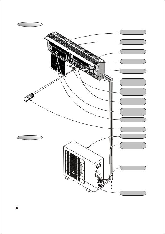
1Identification of Parts
Indoor Unit
Air Intake
Front Panel
Emergency Panel
Display Panel
Air Outlet
Vertical Adjustment
Louver
Horizontal Adjustment
Louver
Charcoal Filter
(optional)
Electrostatic Filter
(optional)
Air Filter
Remote Control
Air Intake
Outdoor Unit
Pipes and Power
Connection Cord
Drain Hose
Note: Condensate water drains at COOLING or DRY operation.
Air Outlet
The figures in this manual are based on the external view of a standard model. Consequently, the shape may differ from that of the air conditioner you have selected.
2
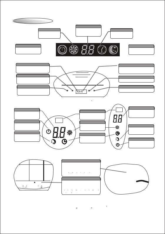
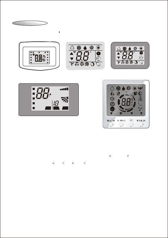
1Identification of Parts
Operating and Display
|
Temperature display |
Run Indicator |
Display of environm- |
|
ental temperature or |
It is on during
setting temperature
operation.
Power Indicator
It lights up when  power supply is on.
Timer Indicator
It lights up during the set time.
Sleep Indicator
 It lights up during the set sleep function
The above operating sketch map is suitable for Z BG series.
Signal Receives
Receive signal from the remote control.
Sleep Indicator
It lights up during the set sleep function
Power Indicator
It lights up when power supply is on.
POWER SLEEP |
TIMER RUN |
Temperature display(optional)
Display of environmental temperature or setting temperature
Timer Indicator
It lights up during the set time.
Run Indicator
It is on during operation.
The above operating sketch map is suitable for C D E
E F
F G
G H
H J
J K
K M
M  N
N V
V Z
Z BD
BD BE
BE BF
BF BH and BJ series.
Temperature display
Display of environmental temperature or setting temperature
Power Indicator
It lights up when power supply is on.
Sleep Indicator
It lights up during the set sleep function
Signal Receives
Receive signal from the remote control.
Run Indicator
It is on during operation.
Timer Indicator
It lights up during the set time.
Temperature display
Display of environmental temperature or setting temperature
Sleep Indicator
It lights up during the set sleep function
Power Indicator
It lights up when power supply is on.
The above operating sketch map is suitable for L R and Y series.
The above operating sketch map is suitable for Q series.
|
|
|
|
|
|
|
|
|
|
|
|
|
|
|
|
Emergency Button |
|
|
|
|||||
|
|
|
|
|
|
|
|
|
|
|
|
|
|
Used to control the unit when the |
|
|
|
|||||||
|
|
|
|
|
|
|
|
|
|
|
|
|
|
remote control is out of work. |
|
|
|
|||||||
|
|
|
|
|
|
|
|
|
|
|
|
|
|
|
|
|||||||||
|
|
|
|
|
|
|
|
|
|
|
|
|
|
This way of operation is suitable |
|
|
|
|||||||
|
|
|
|
|
|
|
|
|
|
|
|
|
|
for C |
D |
N |
R |
L |
M |
Y and |
|
ON/OFF |
||
|
|
|
|
|
|
|
|
|
|
|
|
|
|
Z series. |
|
|
|
|
|
|
|
|
||
|
|
|
|
|
|
|
|
|
|
|
|
|
|
|
|
Emergency Button |
|
|
|
|
||||
|
|
|
|
|
|
|
|
|
|
|
|
|
|
Used to control the unit when the |
|
|
|
|||||||
|
|
|
ON/OFF |
|
|
|
|
|
|
|||||||||||||||
|
|
|
|
|
|
|
|
|
|
|
|
|
|
remote controller is out of work. |
|
|
|
|||||||
|
|
|
|
|
|
|
|
|
|
|
|
|
|
|
|
|
||||||||
|
|
|
|
|
|
|
|
|
|
|
|
|
|
This way of operationis suitable for |
|
|
|
|||||||
|
|
|
|
|
|
|
|
|
|
|
|
|
|
|
|
|
||||||||
|
|
|
|
|
|
|
|
|
|
|
|
|
|
E |
F |
G |
H |
J |
K |
Q |
Z BD |
|
|
|
|
|
|
|
|
|
|
|
|
|
|
|
|
|
BE |
BF |
BG |
BH and BJ series. |
|
|
|
||||
Remarks:When remote control is not working properly,,open the panel and you can see emergency button there,(see above picture).The emergency button for 15K 16K 18K
18K 22K
22K 24K
24K
 28K and 30K series is at the top right,see ON/OFF button there.
 The shape and position of the switches and indicators may vary from different models,but their function are simiar.
3
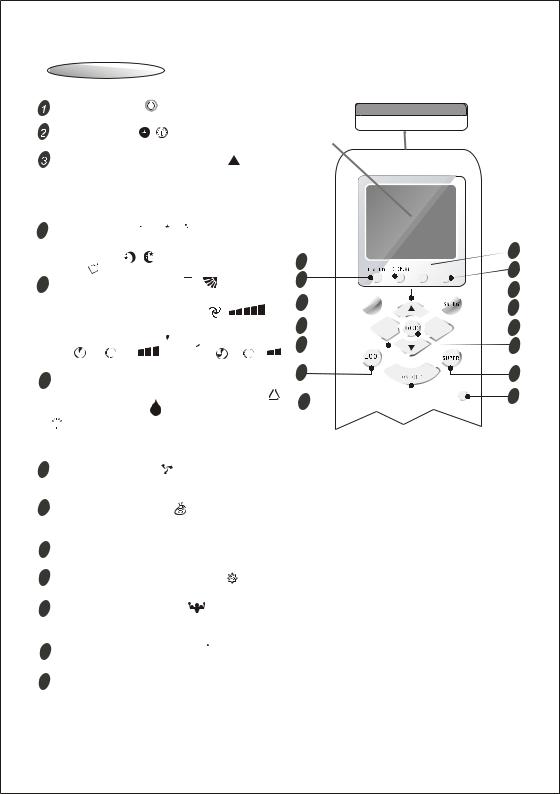
1Remote Control
Remote Control
The remote control transmits signals to the system.
ON/OFF button |
Signal Transmitting Window |
Used to start and stop operation . |
Transmits signals to the system. |
TIMER button |
Setting Display |
Used to select TIMER operation. |
|
UP button (TOO COOL button) |
|
Used to increase the set room temperature (60 f ~87 f) and time(0.5~24h or 1~12h ).
 DOWN button (TOO WARM button)
Used to decrease the set room temperature and time.
 SLEEP button

 QUIET
QUIET
Used to set or cancel sleep operation.It includes normal-SLEEP(
 QUIET )and ComfortableSLEEP(
 ),but Comfortable-SLEEP is optional.
 SWING control button

Used to adjust airflow direction.
 FAN SPEED control button
Used to select the indoor fan motor speed: Auto( or
or  ), High(
  or
or  or
or 

 ),
),
Mid(  or
or  or
or  ) and Low(
  or or ).
This function is invalid in sleep mode.
 MODE button
Used to select the type of operation mode: FEEL( ), COOLING(  ), DRY( ), FAN(
 ) AND HEATING
11
14
7


5


4
10
1 
(
 Only for Heat Pump).FEEL mode can select the operation
9 


 12 3
12 3  6
6


 2 8
2 8
13
15
RESET
mode such as COOL,DRY,FAN,HEAT automatically depending on the room temperature,and the feel mode is
default setting at starting. |
|
|
9 |
3D button(optional) |
|
|
Used to start and stop 3D operation .Two-direction Airflow,the horizontal louver is opened different |
|
|
direction in different mode(optional). |
|
10 ECO. button(optional) |
EC |
|
|
(This function does not apply to the Units of KFTHP-12, KFTHP-18, and KFTHP-24. ) |
|
|
Used to start and stop ECONOMY operation .This function is invalid in SUPER mode. |
|
11 |
DISPLAY button(optional) |
|
|
Used to start and stop DISPLAY screen operation . |
|
12 |
ANTI-MILDEW button(optional) |
|
|
Used to start and stop ANTI-MILDEW operation . |
|
13 |
SUPER button(optional) |
POWERFUL |
(This function does not apply to the Units of KFTHP-12, KFTHP-18, and KFTHP-24. ) Used to start and stop SUPER operation .
14HEALTHY button(optional)

Used to start and stop HEALTHY operation .
15 RESET button(optional)
Used to restart.
Note:The position and figure of buttons are subject to the actual unit,;the relevant function is not activated even if press the optional button which is invalid for some models;
Each mode and relevant function will be further specified in following pages.
4
1Remote Control
Remote Control
Some remote control s display:
SLEEP |
TIMER ON TMIER OFF |
FEEL |
AUTO |
COOL |
HIGH |
DRY |
MID |
FAN |
LOW |
HEAT |
SWING |
Feel Cool Dry Fan Heat
C |
C |
Timer |
off |
||
h |
h |
Timer |
on |
Auto Low Mid High Sleep Swing
|
Style.1 |
|
Style.2. |
Style.3 |
FEEL |
|
|
FAN |
|
|
AUTOQUIET |
SPEED |
|
|
COOL |
|
AIR |
|
|
|
POWERFUL |
|
||
DRY |
C AUTO |
SWING |
|
|
FAN |
|
hr |
|
|
HEAT |
|
DELAY |
|
|
ON |
OFF ON |
|
|
|
|
HEALTHY |
TIMER |
|
|
|
Style.5 |
|
|
|
|
|
|
|
Style.4 |
Note:The above remote control is only for reference, |
subject to the actual unit. |
|||
 When inserting the batteries for the first time or each time the batteries are replaced as they are discharged, the remote control mades a short Auto-Test :all the symbols can be displayed are shown on the screen and keep 2 seconds,then the symbol will flash from Cool to HEAT alternatively.For cooling only air con, please press any button when the cooling symbol is flashing,the the remote controller has been set as cooling only.For cooling and heating ,please press any button
when the heating symbol is flashing,then the remote control has been set as cooling and heating.If none of the button is pressed within 10 seconds,the remote controller will be set as cooling and heating automatically.Cooling only can use the remote
control which has cooling and heating function,but do not have the function of heating. Although the heating is not running,remote control will still have some display.
 The light of the remote control will be turned on by pressing any button for 1.5~3 seconds,and it will be turned off automatically if no button is pressed within 10 seconds.
5
1Remote Control
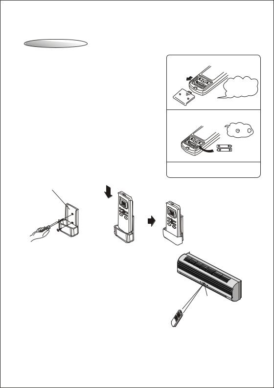
Remote Control
How to Insert the Batteries |
1 Please slide and remove the cover. |
|
Remove the battery cover according to the arrow direction. |
|
|
Insert new batteries making sure that the (+) and (-) of |
Slide the cover |
|
battery are matched correctly. |
||
upwardly in the |
||
Re-attach the cover by sliding it back into position. |
direction of the |
|
arrow. |
||
Note: |
2 Exchange the batteries. |
|
Use 2 LR03 AAA(1.5volt) batteries. Do not use |
Attention to |
|
rechargeable batteries.Replace batteries with new |
||
the and + |
||
ones of the same type when the display becomes dim. |
marks. |
|
Storage and Tips for Using the Remote Control |
|
The remote control may be mounted on a wall with a holder.
Note: The remote control holder is an optional part.
Remote control holder
FEEL |
SLEEP |
|
COOL |
|
|
DRY |
|
|
FAN |
|
|
HEAT |
|
AUTO |
|
|
HIGH |
|
|
MED |
|
|
LOW |
|
|
SWING |
SLEEP |
|
|
TI |
|
|
MER |
|
FAN |
MODE |
WING |
|
|
|
S |
|
|
ON/ |
|
|
OFF |
3 Install the cover.
FEEL |
|
COOL |
|
DRY |
|
FAN |
AUTO |
HEAT |
HIGH |
|
MED |
|
LOW |
|
SWING |
SLEEP |
|
TI |
FAN |
MER |
|
MODE |
SWING |
|
ON/ |
|
OFF |
How to Use |
|
To operate the room air conditioner, aim |
Signal receptor |
the remote control to the signal receptor. |
|
The remote control will operate the air |
|
conditioner at a distance of up to 10 feet |
|
when pointing at signal receptor of indoor |
|
unit. |
|
6
 Loading...