


ZT3000

8/2007 1
Dealer Setup
& Adjustment Instructions
Simplicity ZT3000 / Snapper 355Z
Zero-Turn Riders & Mowers
TABLE OF CONTENTS:
SAFETY RULES .................................................................2
SETUP PROCEDURES
Quick Setup List ................................................................3
Uncrating............................................................................4
Battery Activation & Installation ......................................4
Rider Assembly .................................................................5
Seat and Safety Switch Assembly ...................................5
Install Ground Speed Control Levers...............................5
Check Fluid levels .............................................................5
Fill and Check Engine Oil.................................................6
Check Transmission Oil Level .........................................6
Reduce and Check Tire Pressure ....................................6
Torque Mower Blades .......................................................7
Lubrication .........................................................................7
Perform Safety Checks .....................................................8
Functional Tests...............................................................8
Mower Blade Stopping Check..........................................8
Seat Switch Connection...................................................8
Burnish PTO Clutch .........................................................8
Safety Interlock System ...................................................9
ADJUSTMENT PROCEDURES
Seat Adjustments ............................................................10
Ground Speed Control Lever Adjustment.....................10
Operator Adjustment......................................................10
Speed Balancing Adjustment.........................................11
Return-To-Neutral & Neutral Adjustment ......................11
Parking Brake Adjustment..............................................12
Suspension Adjustment .................................................13
PTO Clutch Adjustment ..................................................14
PTO Clutch Adjustment .................................................14
Blade Brake Check ........................................................14
Mower Deck Leveling ......................................................15
Roller Bar Leveling..........................................................16
SERVICE PROCEDURES
Transmission Oil Filter Change .....................................17
Hydraulic Pump Drive Belt Replacement ......................18
Mower Belt Replacement ................................................19
ATTENTION SETUP PERSONNEL:
Sections and items denoted by the Setup symbol
provide the information necessary to fully assemble,
test, and prepare the units described above for
delivery to your customers.
Additional information concerning functional tests,
general adjustment procedures, and the location of
normal lubrication points are included in these
instructions.
The safety warnings provided in this guide and in
the operator's manual included with the unit contain
important information that must be obeyed when
assembling, setting-up, operating, servicing,
transporting, or storing the unit.
These warnings are highlighted by the safety alert triangle
symbol shown above, which signifies that an important safety
message is being provided.
You must read, understand, and follow these warnings and
instructions, and use safe shop and work practices at all
times while working on or around this unit and all other
outdoor power equipment.
Mfg. No. Description
Simplicity Models:
5900660 ZT3000B2444, Simplicity 24HP Briggs & Stratton ZT3000
Zero-Turn Rider with 44” Mower
5900662 ZT3000B2450, Simplicity 24HP Briggs & Stratton ZT3000
Zero-Turn Rider with 50” Mower
5900684 ZT3000B2450CE, Simplicity 24HP Briggs & Stratton
ZT3000 Zero-Turn Rider with 50” Mower (CE/Export)
Snapper Models:
5900681 Snapper 355ZB2444
5900682 Snapper 355ZB2450
5900685 Snapper 355ZB2450CE
Form No. 5101067
Revision 01
Rev. Date: 8/2007
TP 300-7337-01-CH-SMN
This Dealer Setup Instruction covers the following products:

Simplicity / Snapper ZTR
TP 300-7337-01-CH-SMN
8/20072
Read these safety rules and follow them closely. Failure to obey these rules could result in loss of control of equipment, severe
personal injury or death to you, yourself or bystanders, or damage to property or equipment. This mowing deck is capable of
amputating hands and feet and throwing objects. The triangle in text signifies important cautions or warnings which must be
followed.
IMPORTANT – Safe operation practices for riding mowers.
I. General operation
1. Read, understand, and follow all instructions in the manual and on
the unit before starting.
2. Only allow responsible adults, who are familiar with the
instructions, to operate the unit.
3. Clear the area of objects such as rocks, toys, wire, etc., which
could be picked up and thrown by the blade(s).
4. Be sure the area is clear of other people before mowing. Stop the
unit if anyone enters the area.
5. Never carry passengers.
6. Do not mow in reverse unless absolutely necessary. Always look
down and behind before and while backing.
7. Be aware of the mower discharge direction and do not point it at
anyone. Do not operate the mower without either the entire grass
catcher or the guard in place.
8. Slow down before turning.
9. Never leave a running unit unattended. Always turn off blades, set
parking brake, stop engine, and remove keys before dismounting.
10. Turn off blades when not mowing.
11. Stop engine before removing grass catcher or unclogging chute.
12. Mow only in daylight or good artificial light.
13. Do not operate the unit while under the influence of alcohol or
drugs.
14. Watch for traffic when operating near or crossing roadways.
15. Use extra care when loading or unloading the unit into a trailer or
truck.
II. Slope operation
Slopes are a major factor related to loss-of-control and tip-over
accidents, which can result in severe injury or death. All slopes require
extra caution. If you cannot back up the slope or if you feel uneasy on
it, do not mow it.
DO
• See your authorized dealer for recommendations of wheel weights
or counterweights to improve stability.
• Mow across slopes, not up and down.
• Remove obstacles such as rocks, tree limbs, etc.
• Watch for holes, ruts, or bumps. Uneven terrain could overturn the
unit. Tall grass can hide obstacles.
• Use slow ground speed so that you will not have to stop or change
speeds while on the slope.
• Use extra care with grass catchers or other attachments. These
can change the stability of the unit.
• Keep all movement on the slopes slow and gradual. Do not make
sudden changes in speed or direction.
• Avoid starting or stopping on a slope. If tires lose traction,
disengage the blade(s) and proceed slowly straight down the
slope.
DO NOT
• Do not turn on slopes unless necessary, and then, turn slowly and
gradually downhill, if possible.
• Do not mow near drop-offs, ditches, or embankments. The unit
could suddenly turn over if a wheel is over the edge of a cliff or
ditch, or if an edge caves in.
• Do not mow on wet grass. Reduced traction could cause sliding.
• Do not try to stabilize the unit by putting your foot on the ground.
• Do not use grass catcher on steep slopes.
III. Children
Tragic accidents can occur if the operator is not alert to the presence
of children. Children are often attracted to the unit and the mowing
activity. Never assume that children will remain where you last saw
them.
1. Keep children out of the mowing area and under the watchful care
of another responsible adult.
2. Be alert and turn unit off if children enter the area.
3. Before and when backing, look behind and down for small
children.
4. Never carry children. They may fall off and be seriously injured or
interfere with safe unit operation.
5. Never allow children to operate the unit.
6. Use extra care when approaching blind corners, shrubs, trees, or
other objects that may obscure vision.
IV. Service
1. Use extra care in handling gasoline and other fuels. They are
flammable and vapors are explosive.
a) Use only an approved container.
b) Never remove gas cap or add fuel with the engine running.
Allow engine to cool before refueling. Do not smoke.
c) Never refuel the unit indoors.
d) Never store the unit or fuel container inside where there is an
open flame, such as a water heater.
d) Clean up oil and fuel spills immediately.
2. Never run a unit inside a closed area.
3. Keep nuts and bolts, especially blade attachment bolts, tight and
keep equipment in good condition.
4. Never tamper with safety devices. Check their proper operation
regularly.
5. Keep equipment free of grass, leaves, or other debris build-up.
6. Stop and inspect the equipment if you strike an object. Repair, if
necessary, before restarting.
7. Never make adjustments or repairs with the engine running.
8. Grass catcher components are subject to wear, damage, and
deterioration, which could expose moving parts or allow objects to
be thrown. Frequently check components and replace, when
necessary, with manufacturer’s recommended parts.
9. Mower blades are sharp and can cut. Wrap the blade(s) or wear
gloves, and use extra caution when servicing them.
10. Check brake operation frequently. Adjust and service as required.
11. Allow the unit to cool before storing.
WARNING – SLOPE OPERATION
Never operate on slopes greater than 15° which is a rise of 5.4 feet
(1,6 m) vertically in 20 feet (6 m) horizontally. Select slow ground
speed before driving onto slope. In addition to front and rear
weights, use extra caution when operating on slopes with rearmounted grass catcher. Mow UP and DOWN the slope, never
across the face, use caution when changing directions and DO
NOT START OR STOP ON SLOPE.
SAFETY RULES

Simplicity / Snapper ZTR
8/2007 3
TP 300-7337-01-CH-SMN
Quick Setup List -
Page Setup Procedure Steps to Perform
4 Uncrating ❏ Remove crate & banding.
❏ Place transmissions in PUSH position & roll off skid.
4 Battery Activation & ❏ Charge the battery
Installation ❏ Test battery with hydrometer or load-tester.
❏ Install & secure battery.
5 Rider Assembly ❏ Install the seat and connect the seat switch
❏ Install ground speed control levers.
6 Check Fluid Levels ❏ Fill & check Engine oil level.
❏ Check transmission fluid level.
❏ Reduce & check tire pressures
(Front tires 40 psi, rear tires 15 psi).
7 Mower Assembly ❏ Torque mower blade bolts.
7 Lubrication ❏ Lubricate all grease & oil points.
8 SAFETY CHECKS ❏ Check for LOOSE HARDWARE.
❏ Check all OPERA
TOR CONTROLS.
❏ Test P
ARKING
BRAKE.
❏ Perform MO
WER BLADE STOPPING CHECK.
(Blade must stop within 5 seconds!)
❏ Perform SAFETY INTERLOCK SYSTEM CHECK
.
8 Burnish Electric Clutch ❏ Burnish electric clutch
(run for 15 seconds, repeat 10 times)
.
❏ Repeat MO
WER BLADE STOPPING CHECK.
(Blade must stop within 5 seconds!)
Simplicity / Snapper ZTR
TP 300-7337-01-CH-SMN
8/20074
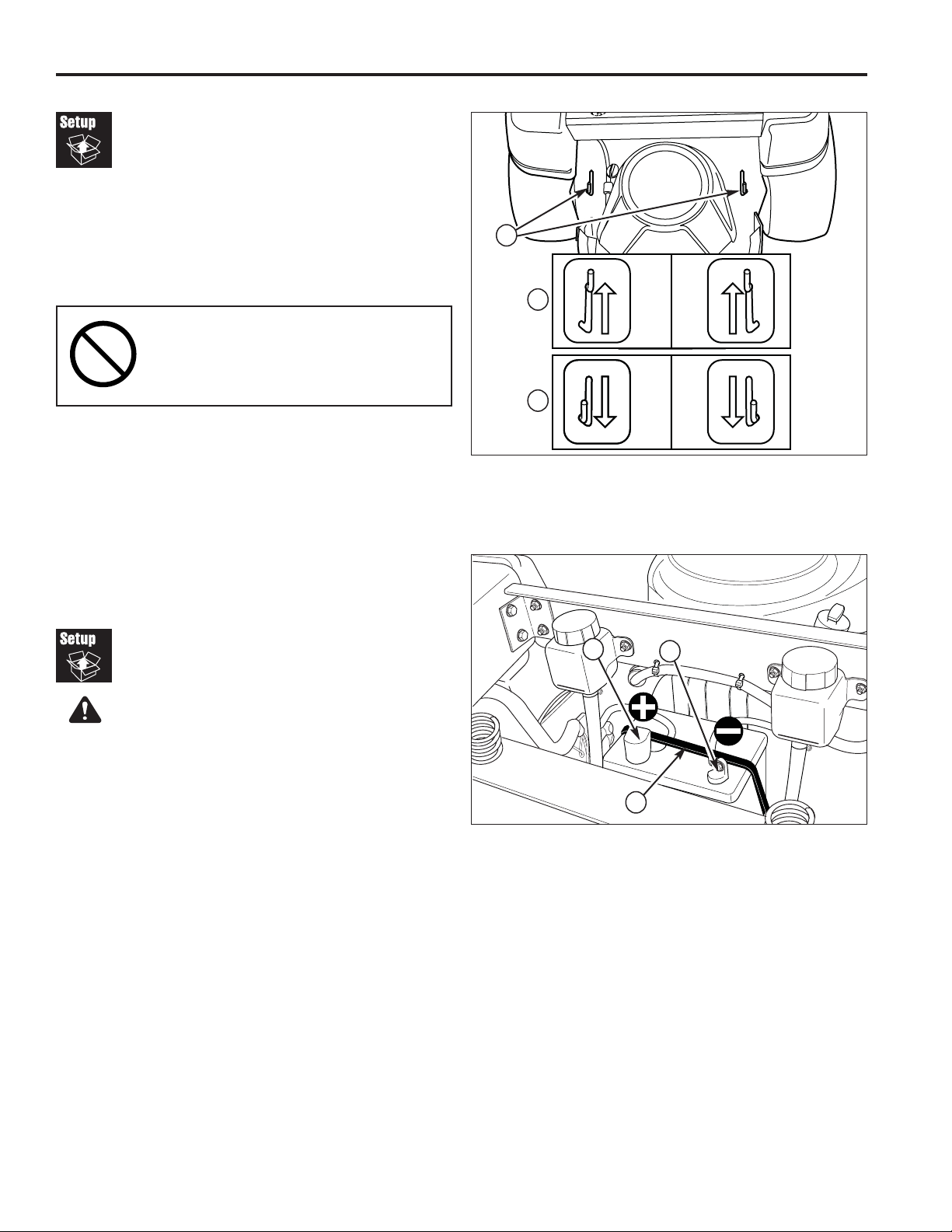
Uncrating
1. Using a reciprocating utility saw or equivalent, cut
crate away from bottom skid. Remove crate. Remove
shrink-wrap plastic.
2. Cut any banding securing the unit.
3. Release parking brake.
4. Pull both transmission release levers (A, Figure 1)
back and out so that they lock in the disengaged
(free-wheel) position (C).
5. Be sure there are no nails or sharp objects on the
bottom of the skid to puncture the tires. Roll the rider
forward off the skid.
6. Engage the transmissions by pulling the hydraulic
release levers rearward and inward to release them
from the disengaged position and allow them to move
forward to the engaged (drive) position (B).
IMPORTANT NOTE
When cutting crate from bottom skid,
use caution around tires and mower
rollers.
Battery Activation &
Installation
Charge Battery
1. Tip the seat forward to access the battery.
2. To charge the battery, follow the instructions provided
by the battery charger manufacturer as well as all
warnings included in the safety rules section of this
document. Charge the battery until fully charged
(until the specific gravity of the electrolyte is 1.250 or
higher and the electrolyte temperature is at least 60°
F). Do not charge at a rate higher than 10 amps.
WARNING
BATTERY SAFETY RULES
• Battery acid causes severe burns. Avoid contact
with skin.
• Wear eye protection while handling the battery.
• To avoid an explosion, keep flames and sparks
away from battery, especially while charging.
• When installing battery cables, CONNECT THE
POSITIVE (+) CABLE FIRST and negative (-) cable
last. If not done in this order, the positive
terminal can be shorted to the frame by a tool.
Install Battery
1. Install the battery in the battery compartment
2. Connect the red positive battery cable (A) to the
positive battery post.
3. Connect the black negative battery cable (B) to the
negative battery post using a capscrew, washer,
lockwasher and nut.
4. Secure the battery into the battery compartment using
the rubber hold down strap (C). The battery cables
should be underneath the rubber hold-down strap.
Figure 2. Battery
A. Positive Cable & Cover
B. Negative Cable
C. Rubber Hold-Down Strap
Figure 1. Transmission Release Levers
A. Transmission Release Levers
B. Engaged Position (Drive Position)
C. Disengaged Position (Free-wheel Position)
A
B
C
B
A
C
Simplicity / Snapper ZTR
8/2007 5
TP 300-7337-01-CH-SMN
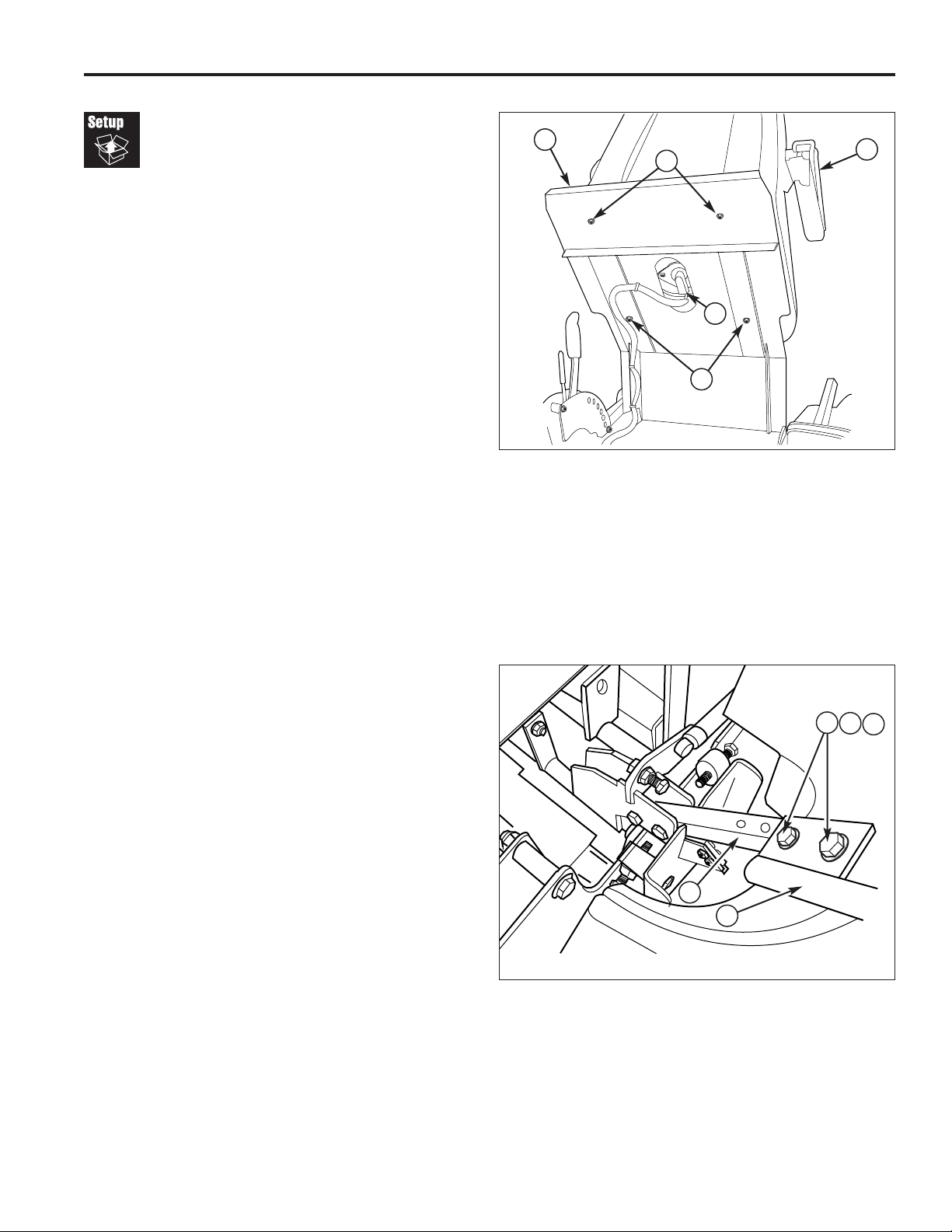
Rider
Assembly
Seat & Safety Switch Assembly
1. Mount the seat (A, Figure 3) to the seat plate (B)
using four 5/16-18 nylock flange nuts (C) and tighten
securely.
2. Connect the seat switch wire harness (D) to the seat
switch.
A
B
C
D
Figure 3. Seat Installation
A. Seat
B. Seat Plate
C. 5/16-18 Nylock Flange Nut (4)
D. Seat Switch Wire Harness
Figure 4. Install Control Levers
A. 5/16-18 x 1” Bolts
B. 5/16 Lockwashers
C. 5/16 Washers
D. Control Lever
E. Control Lever Base
Install Ground Speed Control Levers
1. Mount the ground speed control levers (D, Figure 4)
to the control lever base (E) using four 5/16-18 x 1”
bolts, lockwashers, and washers (A, B & C).
NOTE: Before operating the unit the ground speed
control levers and seat must be adjusted to fit the
operator. See SEAT ADJUSTMENTS and GROUND
SPEED CONTROL LEVER ADJUSTMENTS in the
Adjustments section.
C
A
B
C
D
E
Simplicity / Snapper ZTR
TP 300-7337-01-CH-SMN
8/20076
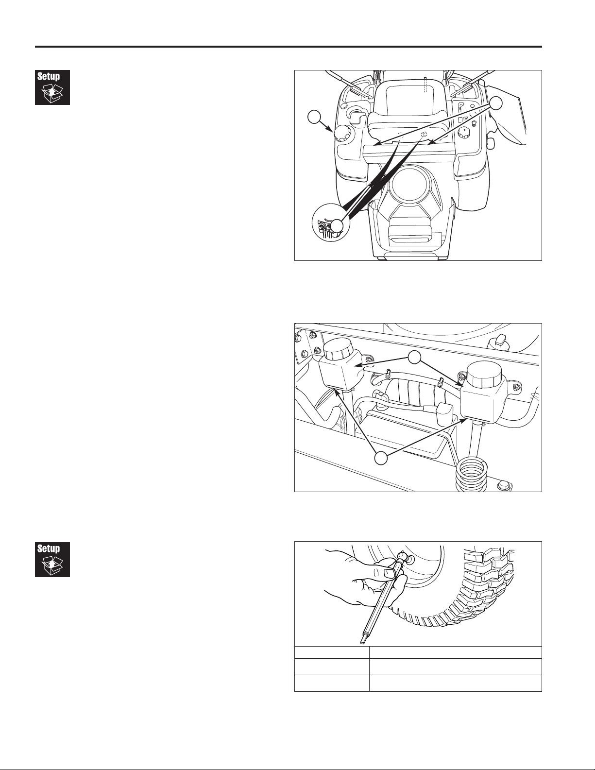
Figure 7. Tire Pressures
Check
Fluid Levels
Fill & Check Engine Oil
1. Use the dipstick (C, Figure 5) to check the engine oil
level. If necessary add engine oil. Check engine
manufacturer’s owner’s manual for oil
recommendations.
Check /Fill Transmission Oil
Oil Type: 20W-50 conventional detergent motor oil.
1. Check the oil level when the unit is cold. Raise the
seat plate to gain access to the transmission oil
reservoirs (A, Figure 6). The oil should be up to the
“FULL COLD” mark. If the oil is below this level,
proceed to step 2.
2. Before removing the reservoir cap, make sure the
area around the reservoir cap and fill neck of the
reservoir is free of dust, dirt, or other debris. Remove
the transmission oil caps (B, Figure 5).
3. Add oil up to the “FULL COLD” mark (B, Figure 6).
4. Reinstall the reservoir cap.
Tire Pressure
Front 40 psi (2,76 bar)
Rear 15 psi (1,03 bar)
Figure 5. Check Fluid Levels
A. Fuel Tank Cap
B. Transmission Oil Caps
C. Engine Oil Dip Stick
Figure 6. Transmission Oil Fill Level
A. Transmission Oil Reservoirs
B. “FULL COLD” Mark
Reduce & Check Tire
Pressures
The tires are over-inflated for shipping purposes. Inflate
to the pressures shown. Note that these pressures may
differ slightly from the “Max Inflation” stamped on the
side-wall of the tires. The pressures shown provide
proper traction, improve cut quality, and extend tire life.
A
B
C
A
B
 Loading...