


 Loading...
Table of contents
1.Precautions for safety and use_________________________ 4
2.Fitting the appliance in the top _________________________ 5
2.1Fixing to the supporting structure ________________________________________5
3.Electrical connection ________________________________ 7
3.1Clearance above and around domestic appliances __________________________8
3.2Room ventilation_____________________________________________________9
3.3Discharge of combustion products _______________________________________9
4.GAS CONNECTION________________________________ 10
5.Adapting to different types of gas______________________ 11
5.1Removing the hob skin _______________________________________________11
5.2Adjusting for bottled gas ______________________________________________12
5.3Adjusting for natural gas ______________________________________________12
5.4Adjusting the primary air flow __________________________________________13
5.5Reassembling the hob skin____________________________________________13
5.6Adjusting the minimum setting for natural gas and town gas __________________13
5.7Adjusting the minimum for bottled gas ___________________________________13
5.8Hob burner layout ___________________________________________________14
5.9Greasing the gas taps________________________________________________14
6.Description of controls ______________________________ 15
6.1The front panel _____________________________________________________15
7.Using the hob _____________________________________ 16
7.1Lighting burners with safety device______________________________________16
7.2Positioning the griddle plate ___________________________________________16
7.3Practical hints for using the burners _____________________________________16
7.4Pan diameters______________________________________________________17
8.Cleaning and maintenance __________________________ 18
8.1Cleaning stainless steel ______________________________________________18
8.2Cleaning the components _____________________________________________18
THESE INSTRUCTIONS ONLY APPLY TO THE COUNTRIES OF DESTINATION WHOSE IDENTIFICATION SYMBOLS ARE LISTED ON THE COVER OF THIS MANUAL.
THIS BUILT-IN HOB IS CLASSIFIED AS CLASS 3.
INSTRUCTIONS FOR THE INSTALLER: these are intended for the authorised person who is to check the gas supply system and install, commission and test the appliance.
INSTRUCTIONS FOR THE USER: these provide recommendations for use, a description of the controls and the correct procedures for cleaning and maintaining the appliance.
3
Precautions for Safety and Use
1.Precautions for safety and use
THIS MANUAL IS AN INTEGRAL PART OF THE APPLIANCE. TAKE GOOD CARE OF IT AND KEEP IT TO HAND THROUGHOUT THE HOB'S LIFE CYCLE. USERS ARE ADVISED TO READ THIS MANUAL AND ALL THE INSTRUCTIONS IT CONTAINS BEFORE USING THE HOB. ALSO KEEP THE SET OF NOZZLES PROVIDED IN A SAFE PLACE. INSTALLATION MUST BE CARRIED OUT BY QUALIFIED STAFF IN COMPLIANCE WITH THE RELEVANT REGULATIONS. THIS APPLIANCE IS INTENDED FOR HOUSEHOLD USE AND COMPLIES WITH THE EEC DIRECTIVES CURRENTLY IN FORCE. THE APPLIANCE IS BUILT TO PROVIDE THE FOLLOWING FUNCTION: COOKING AND HEATING FOODS; ALL OTHER USES ARE TO BE CONSIDERED IMPROPER.
THE MANUFACTURER DECLINES ALL LIABILITY FOR USES OTHER THAN THOSE STATED ABOVE.
NEVER LEAVE PACKAGING RESIDUES UNATTENDED IN THE HOME. SEPARATE WASTE PACKAGING MATERIALS BY TYPE AND CONSIGN THEM TO THE NEAREST SEPARATE DISPOSAL CENTRE.
THE APPLIANCE MUST BE CONNECTED TO EARTH IN COMPLIANCE WITH ELECTRICAL SYSTEM SAFETY REGULATIONS.
THE PLUG TO BE CONNECTED TO THE POWER SUPPLY LEAD AND THE RELATIVE SOCKET MUST BE OF THE SAME TYPE AND COMPLY WITH THE RELEVANT REGULATIONS.
THE POWER SUPPLY SOCKET MUST BE ACCESSIBLE EVEN AFTER THE APPLIANCE HAS BEEN BUILT-IN. NEVER DISCONNECT THE PLUG BY PULLING ON THE POWER SUPPLY LEAD.
IMMEDIATELY AFTER INSTALLATION, CARRY OUT A QUICK TEST ON THE HOB FOLLOWING THE INSTRUCTIONS PROVIDED LATER IN THIS MANUAL. IF THE APPLIANCE FAILS TO OPERATE, DISCONNECT IT FROM THE ELECTRICAL MAINS AND CONTACT YOUR NEAREST SERVICE CENTRE. NEVER ATTEMPT TO REPAIR THE APPLIANCE YOURSELF.
AFTER EACH USE OF THE HOB, ALWAYS CHECK THAT THE CONTROL KNOBS ARE TURNED TO "ZERO" (OFF).
NEVER PLACE PANS WITH BOTTOMS WHICH ARE NOT PERFECTLY FLAT AND SMOOTH ON THE HOB PAN STANDS.
NEVER USE PANS OR GRIDDLE PLATES WHICH PROJECT BEYOND THE OUTSIDE EDGE OF THE HOB.
THE NAMEPLATE WITH THE TECHNICAL DATA, SERIAL NUMBER AND MARK IS IN A VISIBLE POSITION UNDERNEATH THE CASING, ANNEXED TO THIS MANUAL AND APPLIED TO THE QUALITY CERTIFICATE. THIS NAMEPLATE MUST NEVER BE REMOVED.
DO NOT SPRAY AEROSOLS IN THE VICINITY OF THIS APPLIANCE WHILE IT IS IN OPERATION
THIS APPLIANCE IS DESIGNED FOR COOKING FOOD AND IT SHALL NOT BE USED AS A SPACE HEATER.
WHERE THIS APPLIANCE IS INSTALLED IN MARINE CRAFT OR IN CARAVANS, IT SHALL NOT BE USED AS A SPACE HEATER
THE APPLIANCE IS INTENDED FOR USE BY ADULTS. KEEP CHILDREN AT A SAFE DISTANCE AND NEVER ALLOW THEM TO PLAY WITH IT.
The manufacturer declines all responsibility for injury or damage caused by failure to comply with the above regulations or deriving from tampering with even just one part of the appliance and the use of non-original spare parts.
4

Instructions for the Installer
2.Fitting the appliance in the top
The procedures required below must be carried out by a skilled builder and/or joiner. The hob can be installed on various materials, including masonry, metal, solid wood and wood finished with plastic laminates, provided the material is heat-resistant (T 90° C).
2.1Fixing to the supporting structure
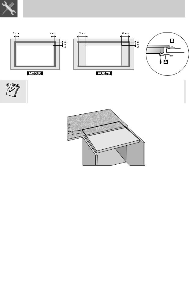
Make a hole in the cabinet top with the dimensions shown here, maintaining a distance of at least 70 mm from the rear edge. This appliance may be installed against lateral walls higher than the worktop surface, provided the distance "X" shown here is maintained, in order to prevent damage due to overheating. Make sure that there is at least 650 mm between the hob burners and a shelf or hood (if any) placed vertically above them.
(*:6 Burner Hob, UR2 at Side)
If the hob is installed above a cupboard with doors, a separator panel must be installed underneath it. Leave a gap of at least 20 mm between the bottom of the hob and the surface of the panel, which must be easily removable to allow sufficient access for any servicing procedures.
IMPORTANT: when installing the appliance above a cupboard, a dividing shelf, as shown above, must be installed.
If installed above an under-bench oven, this is not required.
Installation of an oven without cooking fan underneath the hob is forbidden.
Fit the insulating gasket provided carefully around the outside edge of the hole made in the top as shown below, pressing it down with your hands so that its entire surface fits snugly. Follow the dimensions shown, depending on the model of hob to be installed, bearing in mind that on both models the long front edge must be flush with the hole. Fix the hob to the structure using the brackets A provided. Carefully trim off the excess
5
Instructions for the Installer
edge of the gasket B. The dimensions in the drawing below refer to the hole on the inside edge of the gasket.
In case of installation on a hollow compartment with doors, a separating panel has to be placed under the hob. Keep a minimum distance of 10 mm between the bottom of the unit and the panel surface. The panel has to be easily removable to allow access in the event of technical service.
See right for the precise holes to be used when |
securing the hob to the top correctly using the |
brackets. |
Overall dimensions: location of gas and electrical connection points (all measures in mm).
60 |
|
70 |
cm |
|
cm |
mod. |
|
mod. |
|
|
|
A |
|
B |
|
|
|
|
|
|
14 |
|
6 |
|
|
|
35 30
6
Instructions for the Installer
3.Electrical connection
Check that the power supply line voltage and size are as specified on the nameplate underneath the appliance's casing. This nameplate must never be removed.
The plug on the end of the power supply lead and the wall socket must be of the same type and comply with the relevant regulations. Check that the power supply line is properly earthed.
Pass the power supply cable through the rear of the cabinet, taking care that it does not touch the bottom case of the hob, or the oven (if any) built in underneath it.
The appliance's power supply line must be fitted with an omnipolar breaking device with contact gap of at least 3 mm, located in an easily accessible position close to the appliance itself.
The use of reductions, adapters or junctions is not recommended.
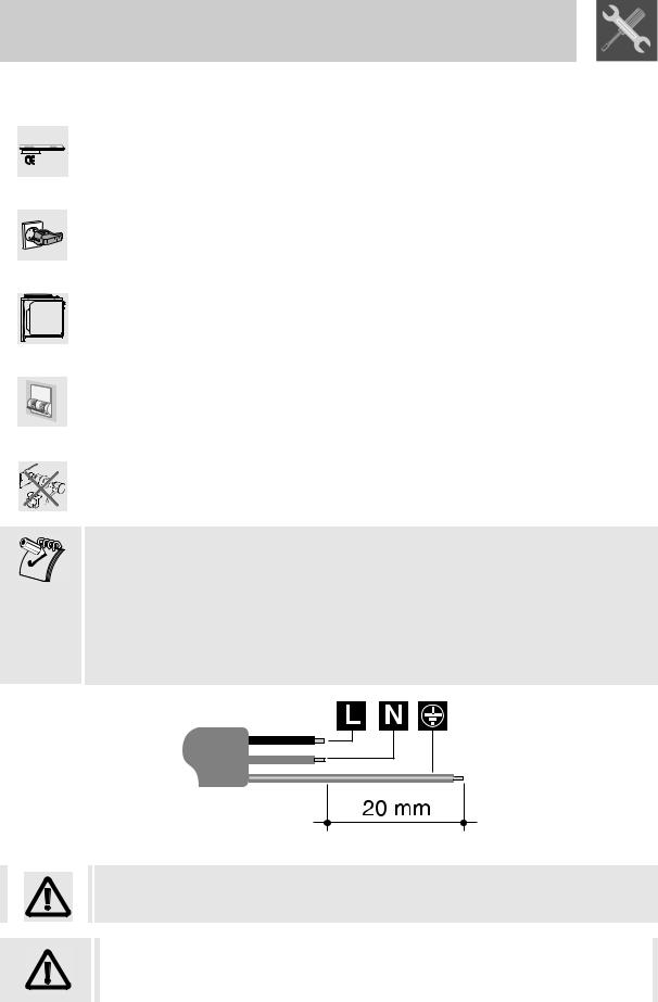
If the power supply cable has to be replaced, the gauge of the wires in the new cable must be at least 0.75 mm2 (3 x 0.75 cable), bearing in mind that the earth wire (yellow-green) must be at least 20 mm longer at the end for connection to the appliance. Use only a type H05V2V2-F or similar cable resistant to a temperature of up to 90°C. The cable must be replaced by a qualified electrician, who must make the mains connection as shown below.
L = brown N = blue
 = yellow-green
The power supply lead must be replaced by an authorised service centre to prevent all risks.
The manufacturer declines all responsibility for injury or damage caused by failure to comply with the above regulations or deriving from tampering with even just one part of the appliance.
7
Loading...