


Reduced wiring system
EtherNet/IP™ Compatible GW Unit
Instruction Manual
EX500-GEN1
URL http:// www.smcworld.com
Specifications are subject to change without prior notice and any obligation on the part of the manufacturer. EtherNet/IP™ is a trademark used under licence by ODVA.
The descriptions of products shown in this document may be used by the other companies as their trademarks. © 2006 SMC Corporation All Rights Reserved

Thank you for purchasing the SMC reduced wiring system EX500 series.
Please read this instruction manual carefully and understand the contents before use so that you can operate this unit safely and correctly.
Please keep this manual handy for future reference.
OPERATOR
 This instruction manual has been written for those who have knowledge of machines and equipments that use reduced wiring system as well as the sufficient knowledge to assemble, operate, and maintain such devices.
maintenance, please read this manual carefully and understand the contents.
To facilitate recycling, this |
|
manual is printed using |
This manual is printed in the |
biodegradable soy ink, which |
"non-water system", which does |
can easily be de-inked. |
not output toxic liquid waste. |
Contents |
|
SAFETY .......................................................................................................... |
2 |
Product Summary............................................................................................ |
5 |
EX500 |
|
Part Names ................................................................................................... |
6 |
Dimensions ................................................................................................... |
7 |
Installation..................................................................................................... |
7 |
Specification.................................................................................................. |
8 |
Wiring.......................................................................................................... |
11 |
Display/Switch setting ................................................................................. |
18 |
SI Unit |
|
Part Names ................................................................................................. |
21 |
Dimensions ................................................................................................. |
22 |
Mounting/Wiring .......................................................................................... |
23 |
Specification................................................................................................ |
24 |
Display ........................................................................................................ |
25 |
Input Unit Manifold |
|
Part Names ................................................................................................. |
26 |
Dimensions ................................................................................................. |
27 |
Installation................................................................................................... |
28 |
Specification................................................................................................ |
29 |
Wiring.......................................................................................................... |
30 |
Display ........................................................................................................ |
31 |
EX9 Series General Purpose Output Block |
|
Part Names ................................................................................................. |
32 |
Dimensions ................................................................................................. |
33 |
Mounting ..................................................................................................... |
34 |
Wiring.......................................................................................................... |
35 |
Specification................................................................................................ |
38 |
Display ....................................................................................................... |
39 |
Option............................................................................................................ |
40 |
Troubleshooting............................................................................................. |
42 |
SAFETY
The body of unit and this manual contain the essential information for the protection of users and others from possible injury and property damage and to ensure correct handling.
Please check that you fully understand the definitions of the following messages
( symbols ) before going on to read the body of this manual, and always follow the instructions.
Please also read the instruction manuals etc. of related machines and equipments and understand the contents before use.
IMPORTANT MESSAGES
Read this manual and follow its instructions. Signal words such as WARNING, CAUTION and NOTE will be followed by important safety information that must be carefully reviewed.
Indicates a potentially hazardous situation that could result in death or severe injury if you do not follow instructions.
|
Indicates a potentially hazardous situation that, if not avoided, |
|
may result in minor injury or moderate injury. |
NOTE |
Gives you helpful information. |
Do not disassemble,
modify ( including modification of printed circuit board ) or repair.
Otherwise injury or failure can result.
Do not operate beyond specification range.
Otherwise fire, malfunction or damage to the reduced wiring system can result. Confirm the specifications before operation.
Do not operate in atmosphere of flammable/explosive/corrosive gas.
Otherwise fire, explosion or corrosion can result.
This reduced wiring system is not explosion-proof type.
For use in interlock circuit:
 Provide double interlock system by adding different type of protection ( such as mechanical protection ).
Check that the interlock circuit is working normally.
Otherwise accident caused by malfunction can result.
Before performing maintenance:
 Turn off power supply.
Stop air supply, exhaust compressed air in piping, and confirm the release to atmosphere.
Otherwise injury can result.
Conduct proper functional inspection after completing maintenance.
In the case of abnormality such as unit does not work normally, stop the operation. Otherwise safety cannot be assured due to unintended malfunction.
Provide grounding to improve safety and noise resistance of reduced wiring system.
Provide grounding as close to the unit as possible to shorten distance for grounding.
Use the following UL-recognized DC power supply to combine with.
1. UL508-compatible limited voltage/current circuit
A circuit using the secondary coil of an insulating transformer that meets following conditions as power source.
 Maximum voltage ( at no load ): 30Vrms ( 42.4Vpeak ) or below
Maximum current : ( 1 ) 8A or less ( including when short-circuited )
( 2 ) When limited by the circuit protector ( such as fuse ) having the following rating.
No-Load Voltage ( Vpeak ) |
Max. Current Rating ( A ) |
0 to 20 [V] |
5.0 |
|
|
Above 20 [V] to 30 [V] |
100/peak voltage |
|
|
2.UL1310-compatible Class 2 power supply unit or circuit of max. 30Vrms ( 42.4Vpeak ) or less using a UL1585-compatible Class 2 transformer as power source. ( Class 2 circuit )
2 |
3 |
SAFETY ( continued )
Follow the instructions given below when handling your reduced wiring system. Otherwise a damage or failure to cause a malfunction can result.
 Operate the reduced wiring system at the specified voltage.
 Reserve space for maintenance.
 Do not remove any name plate or label.
 Do not drop, hit or apply an excessive shock to the unit.
 Follow the specified tightening torque.
 Do not apply any excessive force to cables by repeated bending, tensioning or placing a heavy object on the cables.
 Connect wires and cables correctly.
 Do not perform any wiring work while the power is on.
 Do not use the reduced wiring system on the same wiring route as the power line or high voltage line.
 Confirm the insulation of wiring.
 Perform the power supply wiring by dividing into two lines ---- one is for power supply for output and the other is for power supply for input and controlling GW/SI.
 Take sufficient measures against noise such as noise filter when incorporating the reduced wiring system into a machine or equipment.
 Mount a terminal plug or a waterproof cap on each unused M12 connector for input/output ( communication connector, communication ports A - D, and power supply for input and controlling GW/SI ).
 Take sufficient shielding measures when operating the product in any of the following places. ( 1 ) A place where noise due to static electricity etc. is generated
( 2 ) A place of high electric field strength
( 3 ) A place where exposure to radioactivity is possible ( 4 ) A place near power cable
 Do not operate the product in a place where there is a source of surge.
 Use a surge absorbing element built-in type to directly drive the load that generates surge voltage such as solenoid valve.
 Prevent any foreign matter such as remnant of wires from getting inside the product when opening the station number switch protective cover.
 Install the reduced wiring system in a place free from vibration and impact.
 Operate the product in the specified ambient temperature range.
 Do not use in a place to be affected by the radiant heat from a surrounding heat source.
 Set the DIP switch and rotary switch by using a sharp-pointed watchmakers screwdriver etc.
 Perform the maintenance regularly.
 Conduct an appropriate functional inspection after completing the maintenance. Do not use chemicals such as benzin and thinner to clean the product.
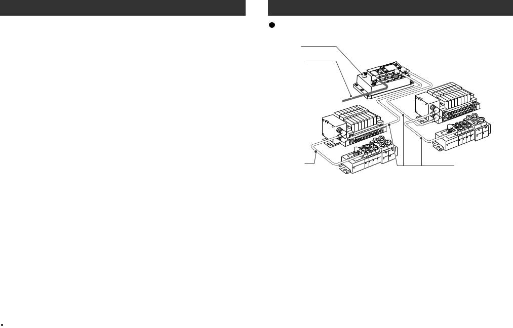
Product Summary
EtherNet/IP communication connector
Power supply connector cable
( 24VDC for solenoid valves/output, 24VDC for input and controlling GW/SI )
Manifold valve with SI unit
( SV/VQC series )
Branch cable
with M12 connector
GW unit
Input unit manifold
Manifold valve with SI unit
( SV/VQC series )
Input unit manifold
Branch cable
with M12 connector
The reduced wiring system is connected to various kinds of fieldbus realizes the reduced wiring and decentralized installation of I/O devices. The signals to/from fieldbus are exchanged by GW unit, and the signals to/from decentralized I/O devices are collected and delivered by GW unit.
The maximum number of connections of manifold valve/Input unit manifold is 16/branch x 4 branches = 64 points each for output and input.
As the cables with connectors are used for all wirings among devices, the system complies with the IP65 environment.
4 |
5 |

EX500 Part Names |
|
Dimensions ( unit : mm ) |
|
|
|
No. |
Name |
Application |
1 |
Communication |
Connect with EtherNet/IP line. ( Note 1 ) |
|
connector |
|
|
|
|
2 |
Power supply connector |
Supply power for output devices such as solenoid |
|
|
valve, for input devices such as sensor, and for |
|
|
controlling GW/SI by using power supply connector |
|
|
cable. ( Note1 ) |
|
|
|
3 |
Communication port A |
|
|
( COM A ) |
|
|
|
|
4 |
Communication port B |
|
|
( COM B ) |
Connect SI unit ( manifold valve ) or Input unit by |
|
|
|
5 |
Communication port C |
using branch cable with M12 connectors. ( Note1 ) |
|
||
|
( COM C ) |
|
|
|
|
6 |
Communication port D |
|
|
( COM D ) |
|
|
|
|
7 |
Display |
Display the power supply status and communication |
|
|
status with PLC. ( Note2 ) |
|
|
|
8 |
Station number switch |
Set IP address and communication method by using |
|
protective cover |
the switches under this cover. ( Note2 ) |
|
|
|
Note1 : For wiring method, refer to subsection "Wiring" ( page 11 ) of section "EX500" in this manual.
Note2 : For display and setting method, refer to subsection "Display/Switch Setting" ( page 18 ) of section "EX500" in this manual.
148
|
|
|
GATEWAY UNIT |
PE |
EX500 |
LAN |
PWR |
|
EX500 SERIES |
||
|
LINK |
|
|
|
- |
|
|
|
|
12 63 73 88 |
G |
|
100 |
|
|
EN1 |
|
|
MS |
|
|
|
|
|
NS |
|
|
|
|
24VDC |
COM A |
COM B |
COM C |
COM D |
|
160
136
46 |
48.8 |
10
Installation ( unit : mm )
Secure at four positions with screws with head diameter of 5.2 or more and thread length of 15mm or more.
148
4 |
M5 |
|
|
Tightening torque : |
|
|
(1.5 0.2) N m |
5 |
|
|
68 |
Cutout Dimensions for Mounting ( Tolerance :  0.2 )
0.2 )
6 |
7 |
Specification
Rated voltage |
24VDC |
|
|
|
|
|
|
|
|
Range of power |
Power supply for input and controlling GW/SI : 24VDC |
|
10% |
|
|
||||
supply voltage |
Power supply for output : 24VDC+10%/-5% ( Voltage drop |
|||
|
warning at around 20V ) |
|
|
|
|
|
|
|
|
Rated current |
Power supply for input and controlling GW/SI : 3.0A |
|||
|
Inside GW unit : 0.2A |
) |
|
|
|
(Input device and SI control section : 2.8A |
|
|
|
|
Power supply for solenoid valves and output : 3A |
|||
|
|
|
|
|
Number of input/ |
Input point : Max. 64/Output point : Max. 64 |
|
|
|
output points |
|
|
|
|
|
|
|
|
|
Protocol |
Ethernet ( IEEE802.3 ) |
||
|
|
|
|
|
Media |
100BASE-TX |
|
|
|
|
|
|
Communication |
10M/100Mbps ( Automatic selection or manual setting ) |
|
|
speed |
||
|
|
|
|
|
|
|
|
|
Max. segment length |
100m ( 328ft ) |
|
|
|||
|
|
|
|
|
Max. transceiver number |
2 ( per segment ) |
|
|
|
|
|
|
Communication |
Full duplex/Half duplex ( automatic selection or manual |
|
|
method |
setting ) |
|
|
|
|
|
Fieldbus protocol |
EtherNet/IP™ Release1.0 |
||
|
|
|
|
|
I/O message |
Input : 16 byte ( assembly instance : 100 ) |
|
|
|
Output : 16 byte ( assembly instance : 150 ) |
|
|
|
|
|
|
Port No. |
44818 ( 0xAF12 ) |
|
|
|
|
|
IP address setting range |
192.168.0.1 to 192.168.0.254 ( Setting by an internal switch ) |
||
|
|
Or optional setting by the DHCP server |
|
|
|
|
|
Device information |
Vendor ID |
: 7 ( SMC Corp. ) |
|
|
|
Product type |
: 12 ( communication adapter ) |
|
|
Product code : 104 |
|
|
|
|
|
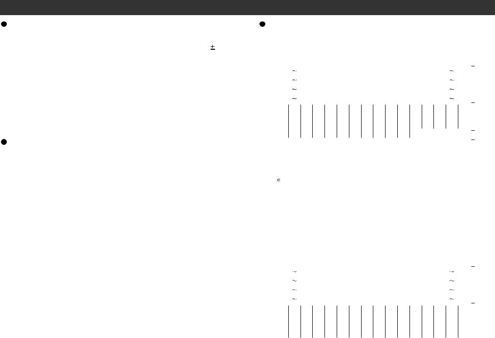
Input area mapping
Offset |
|
|
|
|
|
|
|
|
|
|
|
|
|
|
Input data |
|
|
|
|
|
|
|
|
|
|
|
|
|
|
|
|
||
(word) |
MSB |
|
|
|
|
|
|
|
|
|
|
|
|
|
LSB |
|
MSB |
|
|
|
|
|
|
|
|
|
|
|
|
|
LSB |
|
|
|
15 |
|
|
|
|
|
|
|
|
|
|
|
|
8 |
7 |
|
|
|
|
|
|
|
|
|
|
|
|
0 |
|
|
|||
0 |
15 |
|
|
|
|
|
|
|
|
|
|
|
|
|
COM-A |
|
|
|
|
|
|
|
|
|
|
|
|
|
0 |
|
|
||
1 |
15 |
|
|
|
|
|
|
|
|
|
|
|
|
|
COM-B |
|
|
|
|
|
|
|
|
|
|
|
|
|
0 |
|
Sensor |
||
2 |
15 |
|
|
|
|
|
|
|
|
|
|
|
|
|
COM-C |
|
|
|
|
|
|
|
|
|
|
|
|
|
0 |
|
input area |
||
3 |
15 |
|
|
|
|
|
|
|
|
|
|
|
|
|
COM-D |
|
|
|
|
|
|
|
|
|
|
|
|
|
0 |
|
|
||
4 |
L |
|
L |
|
L |
|
L |
|
L |
|
L |
|
L |
|
L |
|
L |
|
L |
|
L |
|
L |
|
L |
|
L |
|
L |
|
L |
|
|
|
|
|
|
|
|
|
|
|
|
|
|
|
|
|
|
|
|||||||||||||||||
|
|
|
|
|
|
|
|
|
|
|
|
|
|
|
|
|
|
|
|
|
|
|
|
|
|
|
|
|
|
|
|
|
|
5 |
L |
|
L L |
|
L L |
|
L L |
|
L L |
|
L L L |
|
L L |
|
L |
|
L |
|
|
||||||||||||||
|
|
|
|
|
|
|
|
|
|
|
|
|
|
|
|
|
|
|
|
|
|
|
|
|
|
|
|
|
|
|
|
|
|
6 |
L |
|
L L |
|
L L |
|
L L |
|
L L |
|
L L L |
|
L L |
|
L |
|
L |
|
Status |
||||||||||||||
|
|
|
|
|
|
|
|
|
|
|
|
|
|
|
|
|
|
|
|
|
|
|
|
|
|
|
|
|
|
|
|
|
|
7 |
L |
|
L L |
|
L L |
|
L L |
|
L |
|
L |
|
L L |
SOLV |
IN-A |
IN-B |
|
IN-C |
|
IN-D |
|
input area |
|||||||||||
|
|
|
|
|
|
|
|
|
|
|
|
|
|
|
|
|
|
|
|
|
|
|
|
|
|
|
|
|
|
|
|
|
|
L : Fixed to Low ( reserved area )
Status input area specifications
Item |
Status |
|
|
Condition |
|
|
The connection of |
0 |
1) |
The input unit detected |
|
|
|
|
|||
IN- |
2) |
The SI unit with a wire open detection detected |
|||
branched bus |
|
||||
|
|
|
|
||
|
1 |
Wire open detected |
|||
|
|
||||
|
|
|
|
||
|
The power supply of |
0 |
Supply voltage OK |
||
|
|
|
|
||
SOLV |
|
1) |
Supply voltage below lower limit |
||
solenoids |
1 |
||||
|
|
|
|||
|
2) |
No supply voltage |
|||
|
|
|
|||
|
|
|
|
|
|
Output area mapping
Offset |
|
|
|
|
|
|
|
|
|
|
|
|
|
|
Input data |
|
|
|
|
|
|
|
|
|
|
|
|
|
|
|
|
||
(word) |
MSB |
|
|
|
|
|
|
|
|
|
|
|
|
|
LSB |
|
MSB |
|
|
|
|
|
|
|
|
|
|
|
|
|
LSB |
|
|
|
15 |
|
|
|
|
|
|
|
|
|
|
|
|
8 |
7 |
|
|
|
|
|
|
|
|
|
|
|
|
0 |
|
|
|||
0 |
15 |
|
|
|
|
|
|
|
|
|
|
|
|
|
COM-A |
|
|
|
|
|
|
|
|
|
|
|
|
0 |
|
|
|||
1 |
15 |
|
|
|
|
|
|
|
|
|
|
|
|
|
COM-B |
|
|
|
|
|
|
|
|
|
|
|
|
0 |
|
Output |
|||
2 |
15 |
|
|
|
|
|
|
|
|
|
|
|
|
|
COM-C |
|
|
|
|
|
|
|
|
|
|
|
|
0 |
|
area |
|||
3 |
15 |
|
|
|
|
|
|
|
|
|
|
|
|
|
COM-D |
|
|
|
|
|
|
|
|
|
|
|
|
0 |
|
|
|||
4 |
L |
|
L |
|
L |
|
L |
|
L |
|
L |
|
L |
|
L |
|
L |
|
L |
|
L |
|
L |
|
L |
|
L |
|
L |
|
L |
|
|
|
|
|
|
|
|
|
|
|
|
|
|
|
|
|
|
||||||||||||||||||
|
|
|
|
|
|
|
|
|
|
|
|
|
|||||||||||||||||||||
|
|
|
|
|
|
|
|
|
|
|
|
|
|
|
|
|
|
|
|
|
|
|
|
|
|
|
|
|
|
|
|
|
|
5 |
L |
|
L L |
|
L L |
|
L L |
|
L L |
|
L L L |
|
L L |
|
L |
|
L |
|
|
||||||||||||||
|
|
|
|
|
|
|
|
|
|
|
|
|
|
|
|
|
|
|
|
|
|
|
|
|
|
|
|
|
|
|
|
|
|
6 |
L |
|
L L |
|
L L |
|
L L |
|
L L |
|
L L L |
|
L L |
|
L |
|
L |
|
|
||||||||||||||
|
|
|
|
|
|
|
|
|
|
|
|
|
|
|
|
|
|
|
|
|
|
|
|
|
|
|
|
|
|
|
|
|
|
7 |
L |
|
L L |
|
L L |
|
L L |
|
L L |
|
L L L |
|
L L |
|
L |
|
L |
|
|
||||||||||||||
|
|
|
|
|
|
|
|
|
|
|
|
|
|
|
|
|
|
|
|
|
|
|
|
|
|
|
|
|
|
|
|
|
|
L : Fixed to Low ( reserved area )
8 |
9 |
Specification ( continued )
Number of branches for |
4 branches ( 16 points/branch ) for input |
|
input/output |
4 branches ( 16 points/branch ) for output |
|
|
|
|
Communication method |
Protocol : Dedicated for SMC |
|
|
Speed : 750kbps |
|
|
|
|
Branch current for input |
Max. 0.5 [A] per branch ( when SI unit and input |
|
( Note ) |
devices are connected ) |
|
|
|
|
Branch current for output |
Max. 0.65 [A] per branch |
|
|
( when SI unit EX500-S |
01 is connected ) |
|
Max. 0.75 [A] per branch |
|
|
( when SI unit EX500-Q |
is connected ) |
|
|
|
Branch cable length |
5m or less between devices |
|
|
( total extended length : 10m or less ) |
|
|
|
|
Note : Total value of maximum current consumption and maximum load current of input devices to connect.
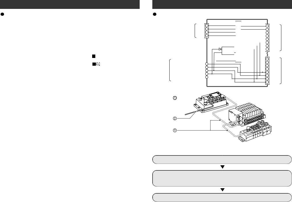
Wiring
+Tx 1
Communication +Rx 2 connector - Tx 3
- Rx 4
|
Power supply |
|
0V |
|
|
|
|
|||
Power |
for output |
|
1 |
|
|
|||||
+24V |
2 |
|
|
|||||||
Power supply |
|
|
||||||||
supply |
|
0V |
3 |
|
|
|||||
connector |
for input and |
+24V |
4 |
|
|
|||||
|
controlling GW/SI |
|
PE |
5 |
|
|
||||
|
|
|
|
|||||||
|
|
|
|
|
|
|
|
|
|
|
|
|
|
|
|
|
|
|
|
|
|
|
|
|
|
|
|
|
|
|
|
|
|
|
|
|
|
|
|
|
|
|
|
|
|
|
|
|
|
|
|
|
|
|
DC-DC converter

 Internal circuit
1RD+
2RD -
3TD+
4TD -
5+24V
60V
7+24V
80V
1RD+
2RD -
3TD+
4TD -
5+24V
60V
7+24V
80V
COM A
COM D
The wirings is explained in the following order.
 Communication wiring : Connection with EtherNet/IP
 Power supply wiring : Connections of power supplies for solenoid valves/output devices, and for input devices and controlling GW/SI
 Branch wiring : Connection from GW unit to SI unit or Input unit
10 |
11 |
 Loading...