


 Loading...
EliteConnect™ Universal
2.4GHz/5GHz Wireless Dual-Band Outdoor Access Point/Bridge
The easy way to make all your network connections
38 Tesla |
May 2005 |
|
Irvine, CA 92618 |
||
Revision Number: R01 |
||
Phone: (949) 679-8000 |
||
F1.1.2.5 |
Copyright
Information furnished by SMC Networks, Inc. (SMC) is believed to be accurate and reliable. However, no responsibility is assumed by SMC for its use, nor for any infringements of patents or other rights of third parties which may result from its use. No license is granted by implication or otherwise under any patent or patent rights of SMC. SMC reserves the right to change specifications at any time without notice.
Copyright © 2005 by SMC Networks, Inc.
38 Tesla
Irvine, CA 92618
All rights reserved.
Trademarks:
SMC is a registered trademark; and EliteConnect is a trademark of SMC Networks, Inc. Other product and company names are trademarks or registered trademarks of their respective holders.
LIMITED WARRANTY
Limited Warranty Statement: SMC Networks, Inc. (“SMC”) warrants its products to be free from defects in workmanship and materials, under normal use and service, for the applicable warranty term. All SMC products carry a standard 90-day limited warranty from the date of purchase from SMC or its Authorized Reseller. SMC may, at its own discretion, repair or replace any product not operating as warranted with a similar or functionally equivalent product, during the applicable warranty term. SMC will endeavor to repair or replace any product returned under warranty within 30 days of receipt of the product.
The standard limited warranty can be upgraded to a Limited Lifetime* warranty by registering new products within 30 days of purchase from SMC or its Authorized Reseller. Registration can be accomplished via the enclosed product registration card or online via the SMC Web site. Failure to register will not affect the standard limited warranty. The Limited Lifetime warranty covers a product during the Life of that Product, which is defined as the period of time during which the product is an “Active” SMC product. A product is considered to be “Active” while it is listed on the current SMC price list. As new technologies emerge, older technologies become obsolete and SMC will, at its discretion, replace an older product in its product line with one that incorporates these newer technologies. At that point, the obsolete product is discontinued and is no longer an “Active” SMC product. A list of discontinued products with their respective dates of discontinuance can be found at: http://www.smc.com/index.cfm?action=customer_service_warranty.
All products that are replaced become the property of SMC. Replacement products may be either new or reconditioned. Any replaced or repaired product carries either a 30-day limited warranty or the remainder of the initial warranty, whichever is longer. SMC is not responsible for any custom software or firmware, configuration information, or memory data of Customer contained in, stored on, or integrated with any products returned to SMC pursuant to any warranty. Products returned to SMC should have any customer-installed accessory or add-on components, such as expansion modules, removed prior to returning the product for replacement. SMC is not responsible for these items if they are returned with the product.
Customers must contact SMC for a Return Material Authorization number prior to returning any product to SMC. Proof of purchase may be required. Any product returned to SMC without a valid Return Material Authorization (RMA) number clearly marked on the outside of the package will be returned to customer at customer’s expense. For warranty claims within North America, please call our toll-free customer support number at (800) 762-4968.
i
LIMITED WARRANTY
Customers are responsible for all shipping charges from their facility to SMC. SMC is responsible for return shipping charges from SMC to customer.
WARRANTIES EXCLUSIVE: IF AN SMC PRODUCT DOES NOT OPERATE AS WARRANTED ABOVE, CUSTOMER’S SOLE REMEDY SHALL BE REPAIR OR REPLACEMENT OF THE PRODUCT IN QUESTION, AT SMC’S OPTION. THE FOREGOING WARRANTIES AND REMEDIES ARE EXCLUSIVE AND ARE IN LIEU OF ALL OTHER WARRANTIES OR CONDITIONS, EXPRESS OR IMPLIED, EITHER IN FACT OR BY OPERATION OF LAW, STATUTORY OR OTHERWISE, INCLUDING WARRANTIES OR CONDITIONS OF MERCHANTABILITY AND FITNESS FOR A PARTICULAR PURPOSE. SMC NEITHER ASSUMES NOR AUTHORIZES ANY OTHER PERSON TO ASSUME FOR IT ANY OTHER LIABILITY IN CONNECTION WITH THE SALE, INSTALLATION, MAINTENANCE OR USE OF ITS PRODUCTS. SMC SHALL NOT BE LIABLE UNDER THIS WARRANTY IF ITS TESTING AND EXAMINATION DISCLOSE THE ALLEGED DEFECT IN THE PRODUCT DOES NOT EXIST OR WAS CAUSED BY CUSTOMER’S OR ANY THIRD PERSON’S MISUSE, NEGLECT, IMPROPER INSTALLATION OR TESTING, UNAUTHORIZED ATTEMPTS TO REPAIR, OR ANY OTHER CAUSE BEYOND THE RANGE OF THE INTENDED USE, OR BY ACCIDENT, FIRE, LIGHTNING, OR OTHER HAZARD.
LIMITATION OF LIABILITY: IN NO EVENT, WHETHER BASED IN CONTRACT OR TORT (INCLUDING NEGLIGENCE), SHALL SMC BE LIABLE FOR INCIDENTAL, CONSEQUENTIAL, INDIRECT, SPECIAL, OR PUNITIVE DAMAGES OF ANY KIND, OR FOR LOSS OF REVENUE, LOSS OF BUSINESS, OR OTHER FINANCIAL LOSS ARISING OUT OF OR IN CONNECTION WITH THE SALE, INSTALLATION, MAINTENANCE, USE, PERFORMANCE, FAILURE, OR INTERRUPTION OF ITS PRODUCTS, EVEN IF SMC OR ITS AUTHORIZED RESELLER HAS BEEN ADVISED OF THE POSSIBILITY OF SUCH DAMAGES.
SOME STATES DO NOT ALLOW THE EXCLUSION OF IMPLIED WARRANTIES OR THE LIMITATION OF INCIDENTAL OR CONSEQUENTIAL DAMAGES FOR CONSUMER PRODUCTS, SO THE ABOVE LIMITATIONS AND EXCLUSIONS MAY NOT APPLY TO YOU. THIS WARRANTY GIVES YOU SPECIFIC LEGAL RIGHTS, WHICH MAY VARY FROM STATE TO STATE. NOTHING IN THIS WARRANTY SHALL BE TAKEN TO AFFECT YOUR STATUTORY RIGHTS.
*SMC will provide warranty service for one year following discontinuance from the active SMC price list. Under the limited lifetime warranty, internal and external power supplies, fans, and cables are covered by a standard one-year warranty from date of purchase.
SMC Networks, Inc.
38 Tesla
Irvine, CA 92618
ii
COMPLIANCES
Federal Communication Commission Interference
Statement
This equipment has been tested and found to comply with the limits for a Class B digital device, pursuant to Part 15 of the FCC Rules. These limits are designed to provide reasonable protection against harmful interference in a residential installation. This equipment generates, uses and can radiate radio frequency energy and, if not installed and used in accordance with the instructions, may cause harmful interference to radio communications. However, there is no guarantee that interference will not occur in a particular installation. If this equipment does cause harmful interference to radio or television reception, which can be determined by turning the equipment off and on, the user is encouraged to try to correct the interference by one of the following measures:
•Reorient or relocate the receiving antenna
•Increase the separation between the equipment and receiver
•Connect the equipment into an outlet on a circuit different from that to which the receiver is connected
•Consult the dealer or an experienced radio/TV technician for help
Warnings: 1.Wear an anti-static wrist strap or take other suitable measures to prevent electrostatic discharge when handling this equipment.
2.When connecting this device to a power outlet, connect the field ground lead on the tri-pole power plug to a valid earth ground line to prevent electrical hazards.
FCC Caution: Any changes or modifications not expressly approved by the party responsible for compliance could void the user's authority to operate this equipment. This device complies with Part 15 of the FCC Rules. Operation is subject to the following two conditions: (1) This device may not cause harmful interference, and (2) this device must accept any interference received, including interference that may cause undesired operation.
IMPORTANT NOTE:
FCC Radiation Exposure Statement
This equipment complies with FCC radiation exposure limits set forth for an uncontrolled environment. This equipment should be installed and operated with a minimum distance of 20 centimeters (8 inches) between the radiator and your body. This transmitter must not be co-located or operating in conjunction with any other antenna or transmitter.
iii
COMPLIANCES
Wireless 5 GHz Band Statements:
As the SMC2888W access point/bridge can operate in the 5150-5250 MHz frequency band it is limited by the FCC, Industry Canada and some other countries to indoor use only so as to reduce the potential for harmful interference to co-channel Mobile Satellite systems.
High power radars are allocated as primary users (meaning they have priority) of the 5250-5350 MHz and 5650-5850 MHz bands. These radars could cause interference and/or damage to the access point.
EC Conformance Declaration 
 0560
0560
SMC contact for these products in Europe is:
SMC Networks Europe,
Edificio Conata II,
Calle Fructuós Gelabert 6-8, 2o, 4a,
08970 - Sant Joan Despí,
Barcelona, Spain.
Marking by the above symbol indicates compliance with the Essential Requirements of the R&TTE Directive of the European Union (1999/5/EC). This equipment meets the following conformance standards:
•EN 60950 (IEC 60950) - Product Safety
•EN 301 893 - Technical requirements for 5 GHz radio equipment
•EN 300 328 - Technical requirements for 2.4 GHz radio equipment
•EN 301 489-1 / EN 301 489-17 - EMC requirements for radio equipment
Countries of Operation & Conditions of Use in the European Community
This device is intended to be operated in all countries of the European Community. Requirements for indoor vs. outdoor operation, license requirements and allowed channels of operation apply in some countries as described below:
Note: The user must use the configuration utility provided with this product to ensure the channels of operation are in conformance with the spectrum usage rules for European Community countries as described below.
•This device requires that the user or installer properly enter the current country of operation in the command line interface as described in the user guide, before operating this device.
•This device will automatically limit the allowable channels determined by the current country of operation. Incorrectly entering the country of operation may result in illegal operation and may cause harmful interference to other system. The user is obligated to ensure the device is operating according to the channel limitations, indoor/outdoor restrictions and license requirements for each European Community country as described in this document.
iv
COMPLIANCES
•This device employs a radar detection feature required for European Community operation in the 5 GHz band. This feature is automatically enabled when the country of operation is correctly configured for any European Community country. The presence of nearby radar operation may result in temporary interruption of operation of this device. The radar detection feature will automatically restart operation on a channel free of radar.
•The 5 GHz Turbo Mode feature is not allowed for operation in any European Community country. The current setting for this feature is found in the 5 GHz 802.11a Radio Settings Window as described in the user guide.
•The 5 GHz radio's Auto Channel Select setting described in the user guide must always remain enabled to ensure that automatic 5 GHz channel selection complies with European requirements. The current setting for this feature is found in the 5 GHz 802.11a Radio Settings Window as described in the user guide.
•This device is restricted to indoor use when operated in the European Community using the 5.15 - 5.35 GHz band: Channels 36, 40, 44, 48, 52, 56, 60, 64. See table below for allowed 5 GHz channels by country.
•This device may be operated indoors or outdoors in all countries of the European Community using the 2.4 GHz band: Channels 1 - 13, except where noted below.
- In Italy the end-user must apply for a license from the national spectrum authority to operate this device outdoors.
- In Belgium outdoor operation is only permitted using the 2.46 - 2.4835 GHz band: Channel 13.
- In France outdoor operation is only permitted using the 2.4 - 2.454 GHz band: Channels 1 - 7
v

COMPLIANCES
Operation Using 5 GHz Channels in the European
Community
The user/installer must use the provided configuration utility to check the current channel of operation and make necessary configuration changes to ensure operation occurs in conformance with European National spectrum usage laws as described below and elsewhere in this document.
Allowed 5GHz Channels in Each European Community Country
Allowed Frequency Bands |
Allowed Channel Numbers |
Countries |
|
|
|
5.15 - 5.25 GHz* |
36, 40, 44, 48 |
Austria, Belgium |
|
|
|
5.15 - 5.35 GHz* |
36, 40, 44, 48, 52, 56, 60, 64 |
France, |
|
|
Switzerland, |
|
|
Liechtenstein |
|
|
|
5.15 - 5.35* & 5.470 - 5.725 |
36, 40, 44, 48, 52, 56, 60, 64, |
Denmark, Finland, |
GHz |
100, 104, 108, 112, 116, 120, |
Germany, Iceland, |
|
124, 128, 132, 136, 140 |
Ireland, Italy, |
|
|
Luxembourg, |
|
|
Netherlands, |
|
|
Norway, Portugal, |
|
|
Spain, Sweden, |
|
|
U.K. |
|
|
|
5 GHz Operation Not |
None |
Greece |
Allowed |
|
|
|
|
|
*Outdoor operation is not allowed using 5.15-5.35 GHz bands (Channels 36 - 64).
*Currently channels 36-64 are unavailable for use either indoors or outdoors.
vi
COMPLIANCES
Declaration of Conformity in Languages of the European
Community
English |
Hereby, SMC Networks, declares that this Radio LAN device is in |
|
compliance with the essential requirements and other relevant |
|
provisions of Directive 1999/5/EC. |
|
|
Finnish |
Valmistaja SMC Networks vakuuttaa täten että Radio LAN device |
|
tyyppinen laite on direktiivin 1999/5/EY oleellisten vaatimusten ja |
|
sitä koskevien direktiivin muiden ehtojen mukainen. |
|
|
Dutch |
Hierbij verklaart SMC Networks dat het toestel Radio LAN device |
|
in overeenstemming is met de essentiële eisen en de andere |
|
relevante bepalingen van richtlijn 1999/5/EG |
|
Bij deze SMC Networks dat deze Radio LAN device voldoet aan |
|
de essentiële eisen en aan de overige relevante bepalingen van |
|
Richtlijn 1999/5/EC. |
|
|
French |
Par la présente SMC Networks déclare que l'appareil Radio LAN |
|
device est conforme aux exigences essentielles et aux autres |
|
dispositions pertinentes de la directive 1999/5/CE |
|
|
Swedish |
Härmed intygar SMC Networks att denna Radio LAN device står |
|
I överensstämmelse med de väsentliga egenskapskrav och |
|
övriga relevanta bestämmelser som framgår av direktiv 1999/5/ |
|
EG. |
|
|
Danish |
Undertegnede SMC Networks erklærer herved, at følgende udstyr |
|
Radio LAN device overholder de væsentlige krav og øvrige |
|
relevante krav i direktiv 1999/5/EF |
|
|
German |
Hiermit erklärt SMC Networks, dass sich dieser/diese/dieses |
|
Radio LAN device in Übereinstimmung mit den grundlegenden |
|
Anforderungen und den anderen relevanten Vorschriften der |
|
Richtlinie 1999/5/EG befindet". (BMWi) |
|
Hiermit erklärt SMC Networks die Übereinstimmung des Gerätes |
|
Radio LAN device mit den grundlegenden Anforderungen und |
|
den anderen relevanten Festlegungen der Richtlinie 1999/5/EG. |
|
(Wien) |
|
|
Greek |
Με την παρουσα SMC Networks δηλωνει οτι radio LAN device |
|
συµµορφωνεται προσ τισ ουσιωδεισ απαιτησεισ και τισ λοιπεσ |
|
σΧετικεσ διαταξεισ τησ οδηγιασ 1999/5/εκ |
|
|
vii
COMPLIANCES
Italian |
Con la presente SMC Networks dichiara che questo Radio LAN |
|
device è conforme ai requisiti essenziali ed alle altre disposizioni |
|
pertinenti stabilite dalla direttiva 1999/5/CE. |
|
|
Spanish |
Por medio de la presente SMC Networks declara que el Radio |
|
LAN device cumple con los requisitos esenciales y cualesquiera |
|
otras disposiciones aplicables o exigibles de la Directiva 1999/5/ |
|
CE |
|
|
Portuguese |
SMC Networks declara que este Radio LAN device está conforme |
|
com os requisitos essenciais e outras disposições da Directiva |
|
1999/5/CE. |
|
|
Safety Compliance
Power Cord Safety
Please read the following safety information carefully before installing the wireless access point:
WARNING: Installation and removal of the unit must be carried out by qualified personnel only.
•The unit must be connected to an earthed (grounded) outlet to comply with international safety standards.
•Do not connect the unit to an A.C. outlet (power supply) without an earth (ground) connection.
•The appliance coupler (the connector to the unit and not the wall plug) must have a configuration for mating with an EN 60320/IEC 320 appliance inlet.
•The socket outlet must be near to the unit and easily accessible. You can only remove power from the unit by disconnecting the power cord from the outlet.
•This unit operates under SELV (Safety Extra Low Voltage) conditions according to IEC 60950. The conditions are only maintained if the equipment to which it is connected also operates under SELV conditions.
France and Peru only
This unit cannot be powered from IT† supplies. If your supplies are of IT type, this unit must be powered by 230 V (2P+T) via an isolation transformer ratio 1:1, with the secondary connection point labelled Neutral, connected directly to earth (ground).
† Impédance à la terre
viii
COMPLIANCES
Important! Before making connections, make sure you have the correct cord set.
Check it (read the label on the cable) against the following:
Power Cord Set
U.S.A. and |
The cord set must be UL-approved and CSA certified. |
|
Canada |
|
|
The minimum specifications for the flexible cord are: |
||
|
||
|
- No. 18 AWG - not longer than 2 meters, or 16 AWG. |
|
|
- Type SV or SJ |
|
|
- 3-conductor |
|
|
|
|
|
The cord set must have a rated current capacity of at least |
|
|
10 A |
|
|
|
|
|
The attachment plug must be an earth-grounding type with |
|
|
NEMA 5-15P (15 A, 125 V) or NEMA 6-15P (15 A, 250 V) |
|
|
configuration. |
|
|
|
|
Denmark |
The supply plug must comply with Section 107-2-D1, |
|
|
Standard DK2-1a or DK2-5a. |
|
|
|
|
Switzerland |
The supply plug must comply with SEV/ASE 1011. |
|
|
|
|
U.K. |
The supply plug must comply with BS1363 (3-pin 13 A) and |
|
|
be fitted with a 5 A fuse which complies with BS1362. |
|
|
|
|
|
The mains cord must be <HAR> or <BASEC> marked and |
|
|
be of type HO3VVF3GO.75 (minimum). |
|
|
|
|
Europe |
The supply plug must comply with CEE7/7 (“SCHUKO”). |
|
|
|
|
|
The mains cord must be <HAR> or <BASEC> marked and |
|
|
be of type HO3VVF3GO.75 (minimum). |
|
|
|
|
|
IEC-320 receptacle. |
|
|
|
ix

COMPLIANCES
Veuillez lire à fond l'information de la sécurité suivante avant d'installer le wireless access point:
AVERTISSEMENT: L’installation et la dépose de ce groupe doivent être confiés à un personnel qualifié.
•Ne branchez pas votre appareil sur une prise secteur (alimentation électrique) lorsqu'il n'y a pas de connexion de mise à la terre (mise à la masse).
•Vous devez raccorder ce groupe à une sortie mise à la terre (mise à la masse) afin de respecter les normes internationales de sécurité.
•Le coupleur d’appareil (le connecteur du groupe et non pas la prise murale) doit respecter une configuration qui permet un branchement sur une entrée d’appareil EN 60320/IEC 320.
•La prise secteur doit se trouver à proximité de l’appareil et son accès doit être facile. Vous ne pouvez mettre l’appareil hors circuit qu’en débranchant son cordon électrique au niveau de cette prise.
•L’appareil fonctionne à une tension extrêmement basse de sécurité qui est conforme à la norme IEC 60950. Ces conditions ne sont maintenues que si l’équipement auquel il est raccordé fonctionne dans les mêmes conditions.
France et Pérou uniquement:
Ce groupe ne peut pas être alimenté par un dispositif à impédance à la terre. Si vos alimentations sont du type impédance à la terre, ce groupe doit être alimenté par une tension de 230 V (2 P+T) par le biais d’un transformateur d’isolement à rapport 1:1, avec un point secondaire de connexion portant l’appellation Neutre et avec raccordement direct à la terre (masse).
Cordon électrique - Il doit être agréé dans le pays d’utilisation
Etats-Unis et |
Le cordon doit avoir reçu l’homologation des UL et un certificat de la CSA. |
|
Canada: |
|
|
Les spe'cifications minimales pour un cable flexible sont AWG No. 18, |
||
|
||
|
ouAWG No. 16 pour un cable de longueur infe'rieure a` 2 me'tres. |
|
|
- type SV ou SJ |
|
|
- 3 conducteurs |
|
|
|
|
|
Le cordon doit être en mesure d’acheminer un courant nominal d’au moins |
|
|
10 A. |
|
|
|
|
|
La prise femelle de branchement doit être du type à mise à la terre (mise |
|
|
à la masse) et respecter la configuration NEMA 5-15P (15 A, 125 V) ou |
|
|
NEMA 6-15P (15 A, 250 V). |
|
|
|
|
Danemark: |
La prise mâle d’alimentation doit respecter la section 107-2 D1 de la |
|
|
norme DK2 1a ou DK2 5a. |
|
|
|
x

COMPLIANCES
Cordon électrique - Il doit être agréé dans le pays d’utilisation
Suisse: |
La prise mâle d’alimentation doit respecter la norme SEV/ASE 1011. |
|
|
Europe |
La prise secteur doit être conforme aux normes CEE 7/7 (“SCHUKO”) |
|
LE cordon secteur doit porter la mention <HAR> ou <BASEC> et doit être |
|
de type HO3VVF3GO.75 (minimum). |
|
|
Bitte unbedingt vor dem Einbauen des Access Point die folgenden Sicherheitsanweisungen durchlesen (Germany):
WARNUNG: Die Installation und der Ausbau des Geräts darf nur durch Fachpersonal erfolgen.
•Das Gerät sollte nicht an eine ungeerdete Wechselstromsteckdose angeschlossen werden.
•Das Gerät muß an eine geerdete Steckdose angeschlossen werden, welche die internationalen Sicherheitsnormen erfüllt.
•Der Gerätestecker (der Anschluß an das Gerät, nicht der Wandsteckdosenstecker) muß einen gemäß EN 60320/IEC 320 konfigurierten Geräteeingang haben.
•Die Netzsteckdose muß in der Nähe des Geräts und leicht zugänglich sein. Die Stromversorgung des Geräts kann nur durch Herausziehen des Gerätenetzkabels aus der Netzsteckdose unterbrochen werden.
•Der Betrieb dieses Geräts erfolgt unter den SELV-Bedingungen (Sicherheitskleinstspannung) gemäß IEC 60950. Diese Bedingungen sind nur
xi

COMPLIANCES
gegeben, wenn auch die an das Gerät angeschlossenen Geräte unter SELV-Bedingungen betrieben werden.
•
Stromkabel. Dies muss von dem Land, in dem es benutzt wird geprüft werden:
U.S.A und |
Der Cord muß das UL gepruft und war das CSA |
Kanada |
beglaubigt. |
|
|
|
Das Minimum spezifikation fur der Cord sind: |
|
- Nu. 18 AWG - nicht mehr als 2 meter, oder 16 AWG. |
|
- Der typ SV oder SJ |
|
- 3-Leiter |
|
|
|
Der Cord muß haben eine strombelastbarkeit aus |
|
wenigstens 10 A |
|
|
|
Dieser Stromstecker muß hat einer erdschluss mit der typ |
|
NEMA 5-15P (15A, 125V) oder NEMA 6-15P (15A, 250V) |
|
konfiguration. |
|
|
Danemark |
Dieser Stromstecker muß die ebene 107-2-D1, der |
|
standard DK2-1a oder DK2-5a Bestimmungen einhalten. |
|
|
Schweiz |
Dieser Stromstecker muß die SEV/ASE |
|
1011Bestimmungen einhalten. |
|
|
Europe |
Das Netzkabel muß vom Typ HO3VVF3GO.75 |
|
(Mindestanforderung) sein und die Aufschrift <HAR> oder |
|
<BASEC> tragen. |
|
Der Netzstecker muß die Norm CEE 7/7 erfüllen |
|
(”SCHUKO”). |
|
|
xii
TABLE OF CONTENTS
1 Introduction . . . . . . . . . . . . . . . . . . . . . . . . . . . . . 1-1
Package Checklist . . . . . . . . . . . . . . . . . . . . . . . . . . . . . . . . . 1-2
Hardware Description . . . . . . . . . . . . . . . . . . . . . . . . . . . . . . . 1-4
Integrated High-Gain Antenna . . . . . . . . . . . . . . . . . . . . . 1-5
External Antenna Options . . . . . . . . . . . . . . . . . . . . . . . . 1-5
Ethernet Port . . . . . . . . . . . . . . . . . . . . . . . . . . . . . . . . . . 1-5
Power Injector Module . . . . . . . . . . . . . . . . . . . . . . . . . . . 1-6
Receive Signal Strength Indicator (RSSI)
BNC Connector . . . . . . . . . . . . . . . . . . . . . . . . . . . . . 1-7
Grounding Point . . . . . . . . . . . . . . . . . . . . . . . . . . . . . . . . 1-7
Walland Pole-Mounting Bracket Kits . . . . . . . . . . . . . . . 1-7
System Configuration . . . . . . . . . . . . . . . . . . . . . . . . . . . . . . . 1-8
Features and Benefits . . . . . . . . . . . . . . . . . . . . . . . . . . . . . . 1-9
System Defaults . . . . . . . . . . . . . . . . . . . . . . . . . . . . . . . . . . 1-10
2 Network Configuration . . . . . . . . . . . . . . . . . . . . 2-1
Access Point Topologies . . . . . . . . . . . . . . . . . . . . . . . . . . . . 2-1 Ad Hoc Wireless LAN (no Access Point or Bridge) . . . . . 2-2
Infrastructure Wireless LAN . . . . . . . . . . . . . . . . . . . . . . . 2-3 Infrastructure Wireless LAN for Roaming Wireless PCs . 2-4
Bridge Link Topologies . . . . . . . . . . . . . . . . . . . . . . . . . . . . . . 2-5 Point-to-Point Configuration . . . . . . . . . . . . . . . . . . . . . . . 2-6
Point-to-Multipoint Configuration . . . . . . . . . . . . . . . . . . . 2-6
3 Bridge Link Planning . . . . . . . . . . . . . . . . . . . . . 3-1
Radio Path Planning . . . . . . . . . . . . . . . . . . . . . . . . . . . . . . . . 3-1
Antenna Height . . . . . . . . . . . . . . . . . . . . . . . . . . . . . . . . 3-3
Antenna Position and Orientation . . . . . . . . . . . . . . . . . . 3-5
Radio Interference . . . . . . . . . . . . . . . . . . . . . . . . . . . . . . 3-6
Weather Conditions . . . . . . . . . . . . . . . . . . . . . . . . . . . . . 3-7
Ethernet Cabling . . . . . . . . . . . . . . . . . . . . . . . . . . . . . . . . . . . 3-8
Grounding . . . . . . . . . . . . . . . . . . . . . . . . . . . . . . . . . . . . . . . . 3-8
4 Hardware Installation . . . . . . . . . . . . . . . . . . . . . 4-1
Testing Basic Link Operation . . . . . . . . . . . . . . . . . . . . . . . . . |
4-2 |
Mount the Unit . . . . . . . . . . . . . . . . . . . . . . . . . . . . . . . . . . . . |
4-2 |
Using the Pole-Mounting Bracket . . . . . . . . . . . . . . . . . . |
4-2 |
Using the Wall-Mounting Bracket . . . . . . . . . . . . . . . . . . . 4-4
xiii
TABLE OF CONTENTS
Connect External Antennas . . . . . . . . . . . . . . . . . . . . . . . . . . .4-5 Connect Cables to the Unit . . . . . . . . . . . . . . . . . . . . . . . . . . .4-7 Connect the Power Injector . . . . . . . . . . . . . . . . . . . . . . . . . . .4-7 Align Antennas . . . . . . . . . . . . . . . . . . . . . . . . . . . . . . . . . . . . .4-9
5 Initial Configuration . . . . . . . . . . . . . . . . . . . . . . . 5-1
Initial Setup through the CLI . . . . . . . . . . . . . . . . . . . . . . . . . . |
5-2 |
Initial Configuration Steps . . . . . . . . . . . . . . . . . . . . . . . . . |
5-2 |
Using the Web-based Management Setup Wizard . . . . . . . . . |
5-4 |
6 System Configuration . . . . . . . . . . . . . . . . . . . . . 6-1
Advanced Configuration . . . . . . . . . . . . . . . . . . . . . . . . . . . . .6-3
System Identification . . . . . . . . . . . . . . . . . . . . . . . . . . . . .6-4
TCP / IP Settings . . . . . . . . . . . . . . . . . . . . . . . . . . . . . . . .6-7
Radius . . . . . . . . . . . . . . . . . . . . . . . . . . . . . . . . . . . . . . .6-10
PPPoE Settings . . . . . . . . . . . . . . . . . . . . . . . . . . . . . . . .6-13
Authentication . . . . . . . . . . . . . . . . . . . . . . . . . . . . . . . . .6-16
Filter Control . . . . . . . . . . . . . . . . . . . . . . . . . . . . . . . . . .6-26
SNMP . . . . . . . . . . . . . . . . . . . . . . . . . . . . . . . . . . . . . . .6-30
Administration . . . . . . . . . . . . . . . . . . . . . . . . . . . . . . . . .6-33
System Log . . . . . . . . . . . . . . . . . . . . . . . . . . . . . . . . . . .6-38
Wireless Distribution System (WDS) . . . . . . . . . . . . . . . .6-43
Bridge . . . . . . . . . . . . . . . . . . . . . . . . . . . . . . . . . . . . . . .6-45
Spanning Tree Protocol (STP) . . . . . . . . . . . . . . . . . . . .6-47
RSSI . . . . . . . . . . . . . . . . . . . . . . . . . . . . . . . . . . . . . . . .6-54
Radio Interface . . . . . . . . . . . . . . . . . . . . . . . . . . . . . . . . . . .6-56
Radio Settings A (802.11a) . . . . . . . . . . . . . . . . . . . . . . .6-57
Radio Settings G (802.11g) . . . . . . . . . . . . . . . . . . . . . . .6-63
Security (Bridge Mode) . . . . . . . . . . . . . . . . . . . . . . . . . .6-66
Security (Access Point Mode) . . . . . . . . . . . . . . . . . . . . .6-72
Status Information . . . . . . . . . . . . . . . . . . . . . . . . . . . . . . . . .6-87
AP Status . . . . . . . . . . . . . . . . . . . . . . . . . . . . . . . . . . . .6-87
Station Status . . . . . . . . . . . . . . . . . . . . . . . . . . . . . . . . .6-90
Event Logs . . . . . . . . . . . . . . . . . . . . . . . . . . . . . . . . . . .6-92
7 Command Line Interface . . . . . . . . . . . . . . . . . . . 7-1
Using the Command Line Interface . . . . . . . . . . . . . . . . . . . . .7-1
Accessing the CLI . . . . . . . . . . . . . . . . . . . . . . . . . . . . . . .7-1
Telnet Connection . . . . . . . . . . . . . . . . . . . . . . . . . . . . . . .7-1
xiv
TABLE OF CONTENTS
Entering Commands . . . . . . . . . . . . . . . . . . . . . . . . . . . . . . . . 7-3 Keywords and Arguments . . . . . . . . . . . . . . . . . . . . . . . . 7-3
Minimum Abbreviation . . . . . . . . . . . . . . . . . . . . . . . . . . . 7-3 Command Completion . . . . . . . . . . . . . . . . . . . . . . . . . . . 7-3 Getting Help on Commands . . . . . . . . . . . . . . . . . . . . . . . 7-4 Partial Keyword Lookup . . . . . . . . . . . . . . . . . . . . . . . . . . 7-5 Negating the Effect of Commands . . . . . . . . . . . . . . . . . . 7-5 Using Command History . . . . . . . . . . . . . . . . . . . . . . . . . 7-5 Understanding Command Modes . . . . . . . . . . . . . . . . . . 7-6 Exec Commands . . . . . . . . . . . . . . . . . . . . . . . . . . . . . . . 7-6 Configuration Commands . . . . . . . . . . . . . . . . . . . . . . . . 7-7 Command Line Processing . . . . . . . . . . . . . . . . . . . . . . . 7-8
Command Groups . . . . . . . . . . . . . . . . . . . . . . . . . . . . . . . . . 7-9 General Commands . . . . . . . . . . . . . . . . . . . . . . . . . . . . . . . 7-10 configure . . . . . . . . . . . . . . . . . . . . . . . . . . . . . . . . . . . . 7-10
end . . . . . . . . . . . . . . . . . . . . . . . . . . . . . . . . . . . . . . . . . 7-11 exit . . . . . . . . . . . . . . . . . . . . . . . . . . . . . . . . . . . . . . . . . 7-11 ping . . . . . . . . . . . . . . . . . . . . . . . . . . . . . . . . . . . . . . . . 7-12 reset . . . . . . . . . . . . . . . . . . . . . . . . . . . . . . . . . . . . . . . . 7-13 show history . . . . . . . . . . . . . . . . . . . . . . . . . . . . . . . . . . 7-14 show line . . . . . . . . . . . . . . . . . . . . . . . . . . . . . . . . . . . . 7-14
System Management Commands . . . . . . . . . . . . . . . . . . . . 7-15 country . . . . . . . . . . . . . . . . . . . . . . . . . . . . . . . . . . . . . . 7-16
prompt . . . . . . . . . . . . . . . . . . . . . . . . . . . . . . . . . . . . . . 7-18 system name . . . . . . . . . . . . . . . . . . . . . . . . . . . . . . . . . 7-19 username . . . . . . . . . . . . . . . . . . . . . . . . . . . . . . . . . . . . 7-19 password . . . . . . . . . . . . . . . . . . . . . . . . . . . . . . . . . . . . 7-20 ip http port . . . . . . . . . . . . . . . . . . . . . . . . . . . . . . . . . . . 7-20 ip http server . . . . . . . . . . . . . . . . . . . . . . . . . . . . . . . . . 7-21 show system . . . . . . . . . . . . . . . . . . . . . . . . . . . . . . . . . 7-22 show version . . . . . . . . . . . . . . . . . . . . . . . . . . . . . . . . . 7-23
System Logging Commands . . . . . . . . . . . . . . . . . . . . . . . . 7-23 logging on . . . . . . . . . . . . . . . . . . . . . . . . . . . . . . . . . . . 7-24
logging host . . . . . . . . . . . . . . . . . . . . . . . . . . . . . . . . . . 7-24 logging console . . . . . . . . . . . . . . . . . . . . . . . . . . . . . . . 7-25 logging level . . . . . . . . . . . . . . . . . . . . . . . . . . . . . . . . . . 7-25 logging facility-type . . . . . . . . . . . . . . . . . . . . . . . . . . . . 7-26 show logging . . . . . . . . . . . . . . . . . . . . . . . . . . . . . . . . . 7-27
xv
TABLE OF CONTENTS
System Clock Commands . . . . . . . . . . . . . . . . . . . . . . . . . . .7-28 sntp-server ip . . . . . . . . . . . . . . . . . . . . . . . . . . . . . . . . . .7-29
sntp-server enable . . . . . . . . . . . . . . . . . . . . . . . . . . . . . .7-30 sntp-server date-time . . . . . . . . . . . . . . . . . . . . . . . . . . .7-31 sntp-server daylight-saving . . . . . . . . . . . . . . . . . . . . . . .7-31 sntp-server timezone . . . . . . . . . . . . . . . . . . . . . . . . . . . .7-32 show sntp . . . . . . . . . . . . . . . . . . . . . . . . . . . . . . . . . . . .7-33
SNMP Commands . . . . . . . . . . . . . . . . . . . . . . . . . . . . . . . . .7-34 snmp-server community . . . . . . . . . . . . . . . . . . . . . . . . .7-34
snmp-server contact . . . . . . . . . . . . . . . . . . . . . . . . . . . .7-35 snmp-server enable server . . . . . . . . . . . . . . . . . . . . . . .7-36 snmp-server host . . . . . . . . . . . . . . . . . . . . . . . . . . . . . .7-37 snmp-server location . . . . . . . . . . . . . . . . . . . . . . . . . . . .7-38 show snmp . . . . . . . . . . . . . . . . . . . . . . . . . . . . . . . . . . .7-39
Flash/File Commands . . . . . . . . . . . . . . . . . . . . . . . . . . . . . .7-39 bootfile . . . . . . . . . . . . . . . . . . . . . . . . . . . . . . . . . . . . . . .7-40
copy . . . . . . . . . . . . . . . . . . . . . . . . . . . . . . . . . . . . . . . .7-41 delete . . . . . . . . . . . . . . . . . . . . . . . . . . . . . . . . . . . . . . .7-42 dir . . . . . . . . . . . . . . . . . . . . . . . . . . . . . . . . . . . . . . . . . .7-43
RADIUS Client . . . . . . . . . . . . . . . . . . . . . . . . . . . . . . . . . . . .7-45 radius-server address . . . . . . . . . . . . . . . . . . . . . . . . . . .7-45
radius-server port . . . . . . . . . . . . . . . . . . . . . . . . . . . . . .7-46 radius-server key . . . . . . . . . . . . . . . . . . . . . . . . . . . . . . .7-47 radius-server retransmit . . . . . . . . . . . . . . . . . . . . . . . . .7-47 radius-server timeout . . . . . . . . . . . . . . . . . . . . . . . . . . . .7-48 show radius . . . . . . . . . . . . . . . . . . . . . . . . . . . . . . . . . . .7-48
Authentication . . . . . . . . . . . . . . . . . . . . . . . . . . . . . . . . . . . .7-49 802.1x . . . . . . . . . . . . . . . . . . . . . . . . . . . . . . . . . . . . . . .7-51
802.1x broadcast-key-refresh-rate . . . . . . . . . . . . . . . . .7-52 802.1x session-key-refresh-rate . . . . . . . . . . . . . . . . . . .7-53 802.1x session-timeout . . . . . . . . . . . . . . . . . . . . . . . . . .7-54 802.1x supplicant . . . . . . . . . . . . . . . . . . . . . . . . . . . . . .7-55 address filter default . . . . . . . . . . . . . . . . . . . . . . . . . . . .7-56 address filter entry . . . . . . . . . . . . . . . . . . . . . . . . . . . . . .7-57 address filter delete . . . . . . . . . . . . . . . . . . . . . . . . . . . . .7-58 mac-authentication server . . . . . . . . . . . . . . . . . . . . . . . .7-59 mac-authentication session-timeout . . . . . . . . . . . . . . . .7-60 show authentication . . . . . . . . . . . . . . . . . . . . . . . . . . . . .7-60
xvi
TABLE OF CONTENTS
WDS Commands . . . . . . . . . . . . . . . . . . . . . . . . . . . . . . . . . 7-61 wds channel . . . . . . . . . . . . . . . . . . . . . . . . . . . . . . . . . . 7-62
wds mac-address . . . . . . . . . . . . . . . . . . . . . . . . . . . . . . 7-62 wds enable . . . . . . . . . . . . . . . . . . . . . . . . . . . . . . . . . . . 7-63 show wds . . . . . . . . . . . . . . . . . . . . . . . . . . . . . . . . . . . . 7-64
Bridge Commands . . . . . . . . . . . . . . . . . . . . . . . . . . . . . . . . 7-65 bridge timeout . . . . . . . . . . . . . . . . . . . . . . . . . . . . . . . . 7-66
bridge stp-bridge spanning-tree . . . . . . . . . . . . . . . . . . . 7-66 bridge stp-bridge forward-time . . . . . . . . . . . . . . . . . . . . 7-67 bridge stp-bridge hello-time . . . . . . . . . . . . . . . . . . . . . . 7-68 bridge stp-bridge max-age . . . . . . . . . . . . . . . . . . . . . . . 7-69 bridge stp-bridge priority . . . . . . . . . . . . . . . . . . . . . . . . 7-70 bridge stp-port path-cost . . . . . . . . . . . . . . . . . . . . . . . . 7-71 bridge stp-port priority . . . . . . . . . . . . . . . . . . . . . . . . . . 7-72 bridge stp-port portfast . . . . . . . . . . . . . . . . . . . . . . . . . . 7-73 bridge stp-port spanning-disabled . . . . . . . . . . . . . . . . . 7-74 show bridge . . . . . . . . . . . . . . . . . . . . . . . . . . . . . . . . . . 7-75
Filtering Commands . . . . . . . . . . . . . . . . . . . . . . . . . . . . . . . 7-76 filter local-bridge . . . . . . . . . . . . . . . . . . . . . . . . . . . . . . . 7-76
filter ap-manage . . . . . . . . . . . . . . . . . . . . . . . . . . . . . . . 7-77 filter ethernet-type enable . . . . . . . . . . . . . . . . . . . . . . . 7-78 filter ethernet-type protocol . . . . . . . . . . . . . . . . . . . . . . 7-79 show filters . . . . . . . . . . . . . . . . . . . . . . . . . . . . . . . . . . . 7-80
PPPoE Commands . . . . . . . . . . . . . . . . . . . . . . . . . . . . . . . . 7-80 ip pppoe . . . . . . . . . . . . . . . . . . . . . . . . . . . . . . . . . . . . . 7-81
pppoe ip allocation mode . . . . . . . . . . . . . . . . . . . . . . . . 7-82 pppoe ipcp dns . . . . . . . . . . . . . . . . . . . . . . . . . . . . . . . . 7-83 pppoe lcp echo-interval . . . . . . . . . . . . . . . . . . . . . . . . . 7-84 pppoe lcp echo-failure . . . . . . . . . . . . . . . . . . . . . . . . . . 7-85 pppoe local ip . . . . . . . . . . . . . . . . . . . . . . . . . . . . . . . . . 7-86 pppoe remote ip . . . . . . . . . . . . . . . . . . . . . . . . . . . . . . . 7-86 pppoe username . . . . . . . . . . . . . . . . . . . . . . . . . . . . . . 7-87 pppoe password . . . . . . . . . . . . . . . . . . . . . . . . . . . . . . . 7-88 pppoe service-name . . . . . . . . . . . . . . . . . . . . . . . . . . . 7-89 pppoe restart . . . . . . . . . . . . . . . . . . . . . . . . . . . . . . . . . 7-89 show pppoe . . . . . . . . . . . . . . . . . . . . . . . . . . . . . . . . . . 7-90
Ethernet Interface Commands . . . . . . . . . . . . . . . . . . . . . . . 7-91 interface ethernet . . . . . . . . . . . . . . . . . . . . . . . . . . . . . . 7-91
xvii
TABLE OF CONTENTS
dns server . . . . . . . . . . . . . . . . . . . . . . . . . . . . . . . . . . . .7-92 ip address . . . . . . . . . . . . . . . . . . . . . . . . . . . . . . . . . . . .7-93 ip dhcp . . . . . . . . . . . . . . . . . . . . . . . . . . . . . . . . . . . . . . .7-94 shutdown . . . . . . . . . . . . . . . . . . . . . . . . . . . . . . . . . . . . .7-95 show interface ethernet . . . . . . . . . . . . . . . . . . . . . . . . . .7-96
Wireless Interface Commands . . . . . . . . . . . . . . . . . . . . . . . .7-97 interface wireless . . . . . . . . . . . . . . . . . . . . . . . . . . . . . . .7-99
description . . . . . . . . . . . . . . . . . . . . . . . . . . . . . . . . . . . .7-99 ssid . . . . . . . . . . . . . . . . . . . . . . . . . . . . . . . . . . . . . . . .7-100 closed-system . . . . . . . . . . . . . . . . . . . . . . . . . . . . . . . .7-101 speed . . . . . . . . . . . . . . . . . . . . . . . . . . . . . . . . . . . . . .7-101 channel . . . . . . . . . . . . . . . . . . . . . . . . . . . . . . . . . . . . .7-102 turbo . . . . . . . . . . . . . . . . . . . . . . . . . . . . . . . . . . . . . . .7-103 beacon-interval . . . . . . . . . . . . . . . . . . . . . . . . . . . . . . .7-104 dtim-period . . . . . . . . . . . . . . . . . . . . . . . . . . . . . . . . . .7-104 fragmentation-length . . . . . . . . . . . . . . . . . . . . . . . . . . .7-105 rts-threshold . . . . . . . . . . . . . . . . . . . . . . . . . . . . . . . . .7-106 transmit-power . . . . . . . . . . . . . . . . . . . . . . . . . . . . . . . .7-107 max-association . . . . . . . . . . . . . . . . . . . . . . . . . . . . . .7-108 authentication . . . . . . . . . . . . . . . . . . . . . . . . . . . . . . . .7-109 encryption . . . . . . . . . . . . . . . . . . . . . . . . . . . . . . . . . . .7-110 key . . . . . . . . . . . . . . . . . . . . . . . . . . . . . . . . . . . . . . . . .7-112 transmit-key . . . . . . . . . . . . . . . . . . . . . . . . . . . . . . . . . .7-113 multicast-cipher . . . . . . . . . . . . . . . . . . . . . . . . . . . . . . .7-114 wpa-clients . . . . . . . . . . . . . . . . . . . . . . . . . . . . . . . . . .7-116 wpa-mode . . . . . . . . . . . . . . . . . . . . . . . . . . . . . . . . . . .7-117 wpa-preshared-key . . . . . . . . . . . . . . . . . . . . . . . . . . . .7-118 wpa-psk-type . . . . . . . . . . . . . . . . . . . . . . . . . . . . . . . . .7-119 shutdown . . . . . . . . . . . . . . . . . . . . . . . . . . . . . . . . . . . .7-120 show interface wireless . . . . . . . . . . . . . . . . . . . . . . . . .7-120 show station . . . . . . . . . . . . . . . . . . . . . . . . . . . . . . . . .7-121
IAPP Commands . . . . . . . . . . . . . . . . . . . . . . . . . . . . . . . . .7-122 iapp . . . . . . . . . . . . . . . . . . . . . . . . . . . . . . . . . . . . . . . .7-122
VLAN Commands . . . . . . . . . . . . . . . . . . . . . . . . . . . . . . . .7-123 vlan . . . . . . . . . . . . . . . . . . . . . . . . . . . . . . . . . . . . . . . .7-124
native-vlanid . . . . . . . . . . . . . . . . . . . . . . . . . . . . . . . . .7-125
xviii
TABLE OF CONTENTS
A Troubleshooting . . . . . . . . . . . . . . . . . . . . . . . . . A-1
B Specifications . . . . . . . . . . . . . . . . . . . . . . . . . . . B-1
General Specifications . . . . . . . . . . . . . . . . . . . . . . . . . . . . . . B-1
Antenna Specifications . . . . . . . . . . . . . . . . . . . . . . . . . . . . . . B-4
17 dBi Integrated Panel . . . . . . . . . . . . . . . . . . . . . . . . . . B-4
C Cables and Pinouts . . . . . . . . . . . . . . . . . . . . . . . C-1
Twisted-Pair Cable Assignments . . . . . . . . . . . . . . . . . . . . . . C-1
10/100BASE-TX Pin Assignments . . . . . . . . . . . . . . . . . . C-2
Straight-Through Wiring . . . . . . . . . . . . . . . . . . . . . . . . . . C-3
Crossover Wiring . . . . . . . . . . . . . . . . . . . . . . . . . . . . . . . C-3
8-Pin DIN Connector Pinout . . . . . . . . . . . . . . . . . . . . . . . . . . C-4
8-Pin DIN to RJ-45 Cable Wiring . . . . . . . . . . . . . . . . . . . C-5
Glossary
Index
xix
TABLE OF CONTENTS
xx
Chapter 1
Introduction
The SMC EliteConnect Universal 2.4GHz/5GHz Wireless Dual-Band Outdoor Access Point/Bridge system consists of two models that provide point-to-point or point-to-multipoint bridge links between remote Ethernet LANs, and wireless access point services for clients in the local LAN area:
•SMC2888W-S – Includes an integrated high-gain antenna for the 802.11a radio and is designed to operate as a “Slave” bridge in point-to-multipoint configurations, or provide a high-speed point-to-point wireless link between two sites. The 802.11b/g radio requires an external antenna option.
•SMC2888W-M – Provides only external antenna options and is designed to operate as the “Master” bridge in point-to-multipoint configurations, supporting wireless bridge connections to as many as 16 SMC2888W-S Slave units.
Each model is housed in a weatherproof enclosure for mounting outdoors and includes its own brackets for attaching to a wall, pole, radio mast, or tower structure. The unit is powered through its Ethernet cable connection from a power injector module that is installed indoors.
The wireless bridge system offers a fast, reliable, and cost-effective solution for connectivity between remote Ethernet wired LANs or to provide Internet access to an isolated site. The system is also easy to install and operate, ideal for situations where a wired link may be difficult or expensive to deploy. The wireless bridge connection provides data rates of up to 108 Mbps.
1-1
Introduction
In addition, both wireless bridge models offer full network management capabilities through an easy-to-use web interface, a command-line interface, and support for Simple Network Management Protocol (SNMP) tools.
Radio Characteristics – The IEEE 802.11a and 802.11g standards use a radio modulation technique known as Orthogonal Frequency Division Multiplexing (OFDM), and a shared collision domain (CSMA/CA). The 802.11a standard operates in the 5 GHz Unlicensed National Information Infrastructure (UNII) band, and the 802.11g standard in the 2.4 GHz band.
IEEE 802.11g includes backward compatibility with the IEEE 802.11b standard. IEEE 802.11b also operates at 2.4 GHz, but uses Direct Sequence Spread Spectrum (DSSS) and Complementary Code Keying (CCK) modulation technology to achieve a communication rate of up to 11 Mbps.
The wireless bridge provides a 54 Mbps half-duplex connection for each active channel (up to 108 Mbps in turbo mode on the 802.11a interface).
Package Checklist
The Dual-band Outdoor Access Point / Bridge package includes:
•One EliteConnect Universal 2.4GHz/5GHz Wireless Dual-Band Outdoor Access Point/Bridge (SMC2888W-S or SMC2888W-M)
•One Category 5 network cable, length 164 ft (50 m)
•One power injector module and power cord
1-2
Package Checklist
•Outdoor pole-mounting bracket kit
•Outdoor wall-mounting bracket kit
•This User Guide
Inform your dealer if there are any incorrect, missing or damaged parts. If possible, retain the carton, including the original packing materials. Use them again to repack the product in case there is a need to return it.
1-3

Introduction
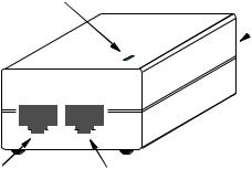
Hardware Description
Bottom View
|
|
|
|
|
|
|
|
|
|
|
|
|
|
|
|
|
|
|
|
|
|
|
|
|
|
|
|
|
|
|
|
|
|
|
RSSI Connector with |
|
Grounding Point |
|
|
|
Ethernet Port |
|
|
|
|||
|
|
|
Protective Cap |
|
Screw |
|
|
Integrated Antenna
Top View (SMC2888W-S)
|
|
|
|
|
|
|
|
|
|
|
|
|
|
|
|
|
|
|
|
|
|
|
|
|
|
|
|
|
|
|
|
|
|
|
|
|
|
|
|
|
|
|
|
|
|
|
|
|
|
|
|
|
|
|
|
|
|
|
|
|
|
|
|
|
|
|
|
|
|
|
|
|
|
|
|
|
|
|
|
|
|
|
|
N-Type External |
|
N-Type External |
|
|
|||||||
Antenna Connector |
|
Antenna Connector |
|
|
|||||||
(2.4 GHz) |
|
(2.4 GHz) |
|
|
|||||||
Top View (SMC2888W-M) |
|
|
|
|
|
|
|||||
|
|
|
|
|
|
|
|
|
|
|
|
|
|
|
|
|
|
|
|
|
|
|
|
|
|
|
|
|
|
|
|
|
|
|
|
|
|
|
|
|
|
|
|
|
|
|
|
|
|
|
|
|
|
|
|
|
|
|
|
|
|
|
|
|
|
|
|
|
|
|
|
|
|
|
|
|
|
|
|
|
|
|
|
N-Type External |
N-Type External |
Antenna Connector |
Antenna Connector |
(2.4 GHz) |
(5 GHz) |
1-4
Hardware Description
Integrated High-Gain Antenna
The SMC2888W-S wireless bridge includes an integrated high-gain (17 dBi) flat-panel antenna for 5 GHz operation.
External Antenna Options
The SMC2888W-M Master bridge unit does not include an integrated antenna, but provides various external antenna options for both 5 GHz and 2.4 GHz operation. In a point-to-multipoint configuration, an external high-gain omnidirectional, sector, or high-gain panel antenna can be attached to communicate with bridges spread over a wide area.
External antennas connect to the N-type RF connectors on the wireless bridge using the provided coaxial cables.
Ethernet Port
The wireless bridge has one 10BASE-T/100BASE-TX 8-pin DIN port that connects to the power injector module using the included Ethernet cable. The Ethernet port connection provides power to the wireless bridge as well as a data link to the local network.
The wireless bridge appears as an Ethernet node and performs a bridging function by moving packets from the wired LAN to the remote end of the wireless bridge link.
Note: The power injector module does not support Power over Ethernet (PoE) based on the IEEE 802.3af standard. The wireless bridge unit must always be powered on by being connected to the power injector module.
1-5
Introduction
Power Injector Module
The wireless bridge receives power through its network cable connection using power-over-Ethernet technology. A power injector module is included in the wireless bridge package and provides two RJ-45 Ethernet ports, one for connecting to the wireless bridge (Output), and the other for connecting to a local LAN switch (Input).
The Input port uses an MDI (i.e., internal straight-through) pin configuration. You can therefore use straight-through twisted-pair cable to connect this port to most network interconnection devices such as a switch or router that provide MDI-X ports. However, when connecting the access point to a workstation or other device that does not have MDI-X ports, you must use crossover twisted-pair cable.
LED Indicator
AC Power Socket
 (Hidden)
Input Output
|
|
|
|
|
|
|
|
|
|
|
|
|
|
|
|
|
|
|
|
|
|
|
|
|
|
|
|
|
|
|
|
|
|
|
|
|
|
|
|
|
|
|
|
|
|
|
|
|
|
|
|
|
|
|
|
|
|
|
|
Ethernet from |
Ethernet and Power to |
||||||||||||||||||
Local Network |
|
|
|
|
Wireless Bridge |
||||||||||||||
The wireless bridge does not have a power switch. It is powered on when its Ethernet port is connected to the power injector module, and the power injector module is connected to an AC power source. The power injector includes one LED indicator that turns on when AC power is applied.
1-6
Hardware Description
The power injector module automatically adjusts to any AC voltage between 100-240 volts at 50 or 60 Hz. No voltage range settings are required.
Warning: The power injector module is designed for indoor use only. Never mount the power injector outside with the wireless bridge unit.
Receive Signal Strength Indicator (RSSI) BNC
Connector
The RSSI connector provides an output voltage that is proportional to the received radio signal strength. A DC voltmeter can be connected this port to assist in aligning the antennas at both ends of a wireless bridge link.
Grounding Point
Even though the wireless bridge includes its own built-in lightning protection, it is important that the unit is properly connected to ground. A grounding screw is provided for attaching a ground wire to the unit.
Walland Pole-Mounting Bracket Kits
The wireless bridge includes bracket kits that can be used to mount the bridge to a wall, pole, radio mast, or part of a tower structure.
1-7
Introduction
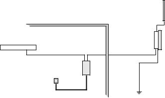
System Configuration
At each location where a unit is installed, it must be connected to the local network using the power injector module. The following figure illustrates the system component connections.
|
|
External Antenna |
Indoor |
Outdoor |
RF Coaxial Cable |
|
||
LAN Switch |
|
Wireless Bridge Unit |
Ethernet Cable |
Ethernet Cable |
|
Power |
|
|
Injector |
|
|
AC Power |
|
Ground Wire |
1-8
Loading...