


MAG 5100 W
INSTRUCTIONS
SITRANS F M MAGFLO
Electromagnetic flowmeter
type MAG 5100 W
ENGLISH
083R9166
SFIDK.PI.026.V1.52
Siemens Flow Instruments SITRANS F M MAGFLO
electromagnetic flowmeters consist of a
sensor and a transmitter. These instructions only describe the sensor installation. For further
information on the transmitter installation, please refer to the SITRANS F M MAGFLO
handbook.
Introduction
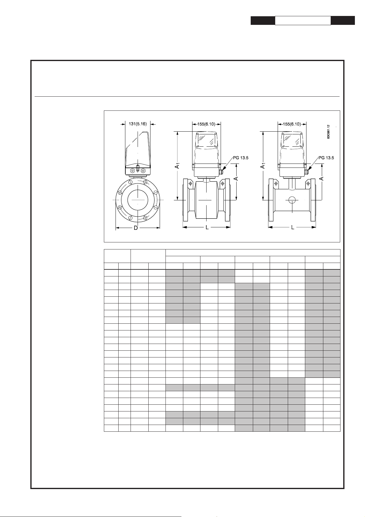
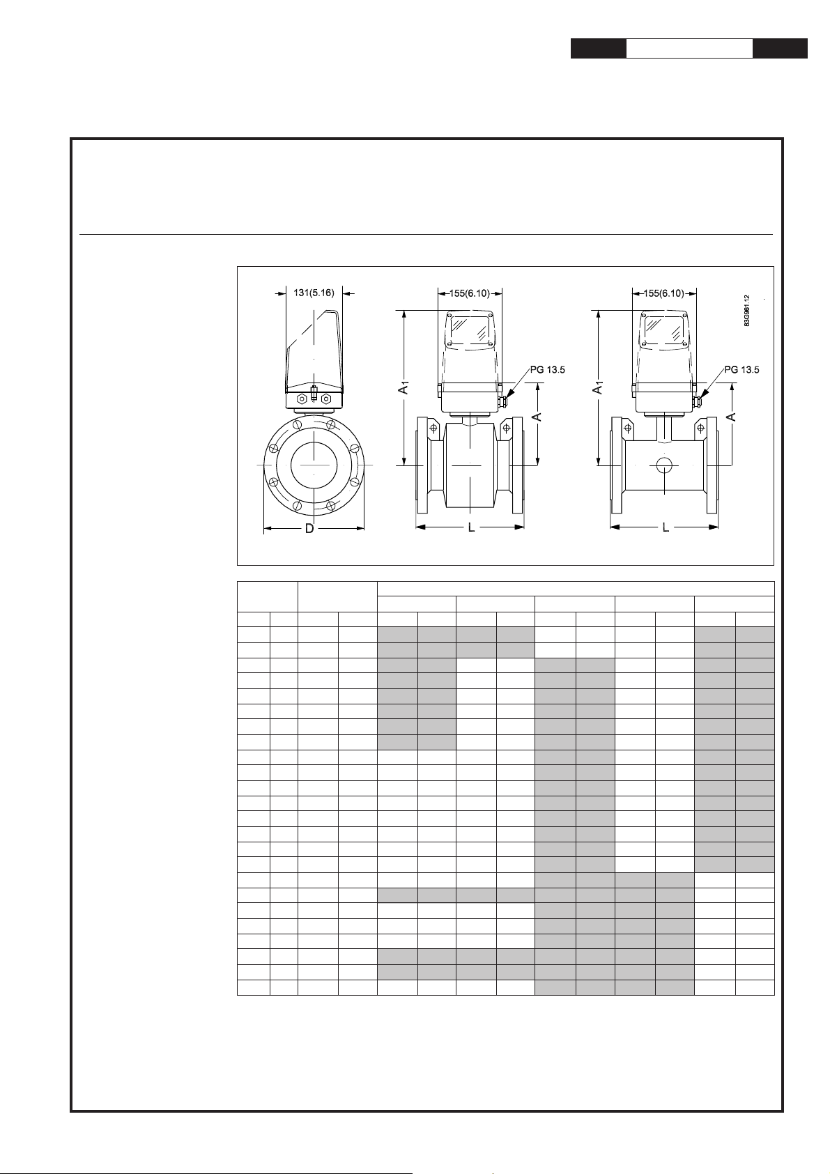
MAG 5100 W, compact/separate
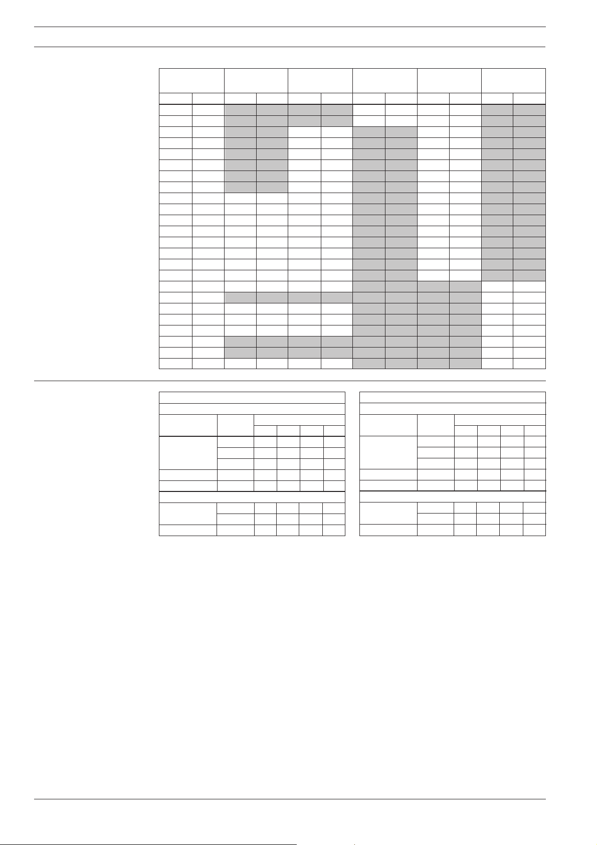
Dimensions and
weight
mm inch mm inch mm inch mm inch mm inch mm inch mm inch
25 1" 187 7.4 N/A N/A N/A N/A 200 7.9 200 7.9 N/A N/A
40 1½” 197 7.8 N/A N/A N/A N/A 200 7.9 200 7.9 N/A N/A
50 2" 188 7.4 N/A N/A 200 7.9 N/A N/A 200 7.9 N/A N/A
65 2½” 194 7.6 N/A N/A 200 7.9 N/A N/A 200 7.9 N/A N/A
80 3" 200 7.9 N/A N/A 200 7.9 N/A N/A 200 7.9 N/A N/A
100 4" 207 8.1 N/A N/A 250 9.8 N/A N/A 250 9.8 N/A N/A
125 5" 217 8.5 N/A N/A 250 9.8 N/A N/A 250 9.8 N/A N/A
150 6" 232 9.1 N/A N/A 300 11.8 N/A N/A 300 11.8 N/A N/A
200 8" 257 10.1 350 13.8 350 13.8 N/A N/A 350 13.8 N/A N/A
250 10" 284 11.2 450 17.7 450 17.7 N/A N/A 450 17.7 N/A N/A
300 12" 310 12.2 500 19.7 500 19.7 N/A N/A 500 19.7 N/A N/A
350 14" 362 14.3 550 21.7 550 21.7 N/A N/A 550 21.7 N/A N/A
400 16" 387 15.2 600 23.6 600 23.6 N/A N/A 600 23.6 N/A N/A
450 18" 418 16.5 600 23.6 600 23.6 N/A N/A 600 23.6 N/A N/A
500 20" 443 17.4 625 24.6 625 24.6 N/A N/A 680 26.8 N/A N/A
600 24" 494 19.4 750 29.5 750 29.5 N/A N/A 820 32.3 N/A N/A
700 28" 544 21.4 875 34.4 875 34.4 N/A N/A N/A N/A 875 34.4
750 30" 571 22.5 N/A N/A N/A N/A N/A N/A N/A N/A 937 36.9
800 32" 606 23.9 1000 39.4 1000 39.4 N/A N/A N/A N/A 1000 39.4
900 36" 653 25.7 1125 44.3 1125 44.3 N/A N/A N/A N/A 1125 44.3
1000 40" 704 27.7 1250 49.2 1250 49.2 N/A N/A N/A N/A 1250 49.2
42" 704 27.7 N/A N/A N/A N/A N/A N/A N/A N/A 1250 49.2
1100 44" 755 29.7 N/A N/A N/A N/A N/A N/A N/A N/A 1375 54.1
1200 48" 810 31.9 1500 59.1 1500 59.1 N/A N/A N/A N/A 1500 59.1
AWWA
Nominal
size
A
L
PN 10
PN 16 PN 40 Class 150
Dimensions
s
Order no.: FDK:521H1190
2
SITRANS F M MAGFLO
Electromagnetic flowmeter type MAG 5100 W
mm inch kgs lbs kgs lbs kgs lbs kgs lbs kgs lbs
25 1" N/A N/A N/A N/A 4 9 4 9 N/A N/A
40 1½" N/A N/A N/A N/A 7 15 6 13 N/A N/A
50 2" N/A N/A 9 20 N/A N/A 8 20 N/A N/A
65 2½" N/A N/A 10.7 24 N/A N/A 11 24 N/A N/A
80 3" N/A N/A 11.6 26 N/A N/A 13 28 N/A N/A
100 4" N/A N/A 15.2 33 N/A N/A 19 41 N/A N/A
125 5" N/A N/A 20.4 45 N/A N/A 24 52 N/A N/A
150 6" N/A N/A 26 57 N/A N/A 29 64 N/A N/A
200 8" 48 106 48 106 N/A N/A 56 124 N/A N/A
250 10" 64 141 69 152 N/A N/A 79 174 N/A N/A
300 12" 76 167 86 189 N/A N/A 110 243 N/A N/A
350 14" 100 220 116 255 N/A N/A 131 289 N/A N/A
400 16" 127 280 144 317 N/A N/A 165 364 N/A N/A
450 18" 152 335 178 393 N/A N/A 176 388 N/A N/A
500 20" 184 405 232 512 N/A N/A 235 518 N/A N/A
600 24" 258 568 343 736 N/A N/A 345 761 N/A N/A
700 28" 315 693 350 772 N/A N/A N/A N/A 309 681
750 30" N/A N/A N/A N/A N/A N/A N/A N/A 480 1058
800 32" 410 904 442 975 N/A N/A N/A N/A 421 928
900 36" 512 1129 550 1213 N/A N/A N/A N/A 539 1188
1000 40" 650 1433 732 1614 N/A N/A N/A N/A 670 1477
42" N/A N/A N/A N/A N/A N/A N/A N/A 700 1544
1100 44" N/A N/A N/A N/A N/A N/A N/A N/A 1100 2426
1200 48" 990 2183 1106 2439 N/A N/A N/A N/A 1030 2271
AWWA
Nominal size
PN 10 PN 16 PN 40 Class 150
Weight
The effect of temperature
on working pressure
Metric (Pressures in bar)
Sizes 25 mm, 40 mm & > 300 mm
Flange spec. Flange Temperature
°°
°°
°C
rating −5105090
EN 1092-1 PN 10 10.0 10.0 9.7 9.4
PN 16 16.0 16.0 15.5 15.1
PN 40 40.0 40.0 38.7 37.7
ANSI B16.45 150 lb 19.7 19.7 19.3 18.0
AWWA C-207 Class D 10.3 10.3 10.3 10.3
Sizes 50 mm to 300 mm
EN 1092-1 PN 10 10.0 10.0 10.0 8.2
PN 16 10.0 16.0 16.0 13.2
ANSI B16.45 150 lb 10.0 19.7 19.7 16.2
Imperial (Pressures in Psi)
Sizes 1", 1½", & > 12"
Flange spec. Flange Temperature
°°
°°
°F
rating 23 50 120 200
EN 1092-1 PN 10 145 145 141 136
PN 16 232 232 225 219
PN 40 580 580 561 547
ANSI B16.45 150 lb 286 286 280 261
AWWA C-207 Class D 150 150 150 150
Sizes 2" to 12"
EN 1092-1 PN 10 145 145 145 119
PN 16 145 232 232 191
ANSI B16.45 150 lb 145 286 286 235
3
SITRANS F M MAGFLO
Electromagnetic flowmeter type MAG 5100 W
Installation, general
Reading and operating the flowmeter is possi-
ble under almost any installation conditions
because the display can be oriented in relation
to the sensor. To ensure optimum flow mea-
surement attention should be paid to the follow-
ing:
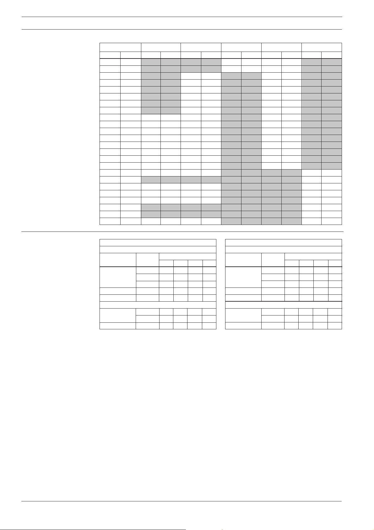
The sensor must always be completely full with
liquid.
Therefore avoid:
• Installation at the highest point in the pipe
system
• Installation in vertical pipes with free outlet
For partially filled pipes or pipes with downward
flow and free outlet the flowmeter should be
located in a U-tube.
Installation in vertical pipes
Recommended flow direction: upwards. This
minimizes the effect on the measurement of
any gas/air bubbles in the liquid.
4
SITRANS F M MAGFLO
Electromagnetic flowmeter type MAG 5100 W
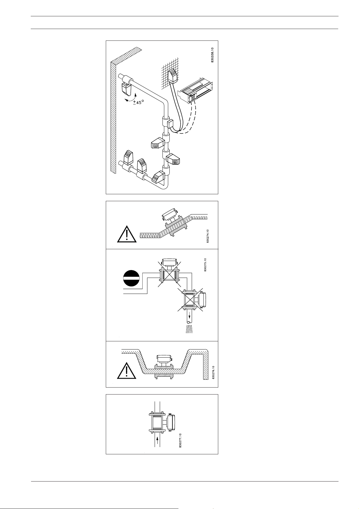
Installation in horizontal pipes
The sensor must be mounted as shown in the
upper figure. Do not mount the sensor as shown
in the lower figure. This will position the elec-
trodes at the top where there is possibility for air
bubbles and at the bottom where there is pos-
sibility for mud, sludge, sand etc.
If using empty pipe detection the sensor can be
tilted 45°, as shown in the upper figure.
Measuring abrasive liquids and liquids con-
taining particles
Recommended installation is in a vertical/in-
clined pipe to minimize the wear and deposits
in the sensor.
Inlet and outlet conditions
To achieve accurate flow measurement it is
essential to have straight lengths of inlet and
outlet pipes and a certain distance between
pumps and valves.
It is also important to centre the flowmeter in
relation to pipe flanges and gaskets.
Installation, general
(continued)
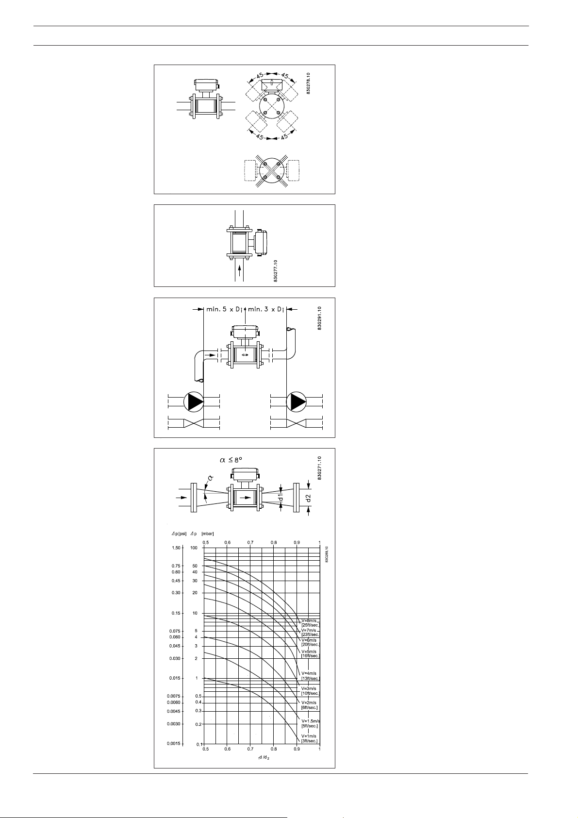
Installation in large pipes
The flowmeter can be installed between two
reducers (e.g. DIN 28545). Assuming that at 8°
the following pressure drop curve applies. The
curves are applicable to water.
Example:
A flow velocity of 3 m/s (V) in a sensor with a
diameter reduction from DN 100 to DN 80
(d
1
/d
2
= 0.8) gives a pressure drop of 2.9 mbar.
5
SITRANS F M MAGFLO
Electromagnetic flowmeter type MAG 5100 W
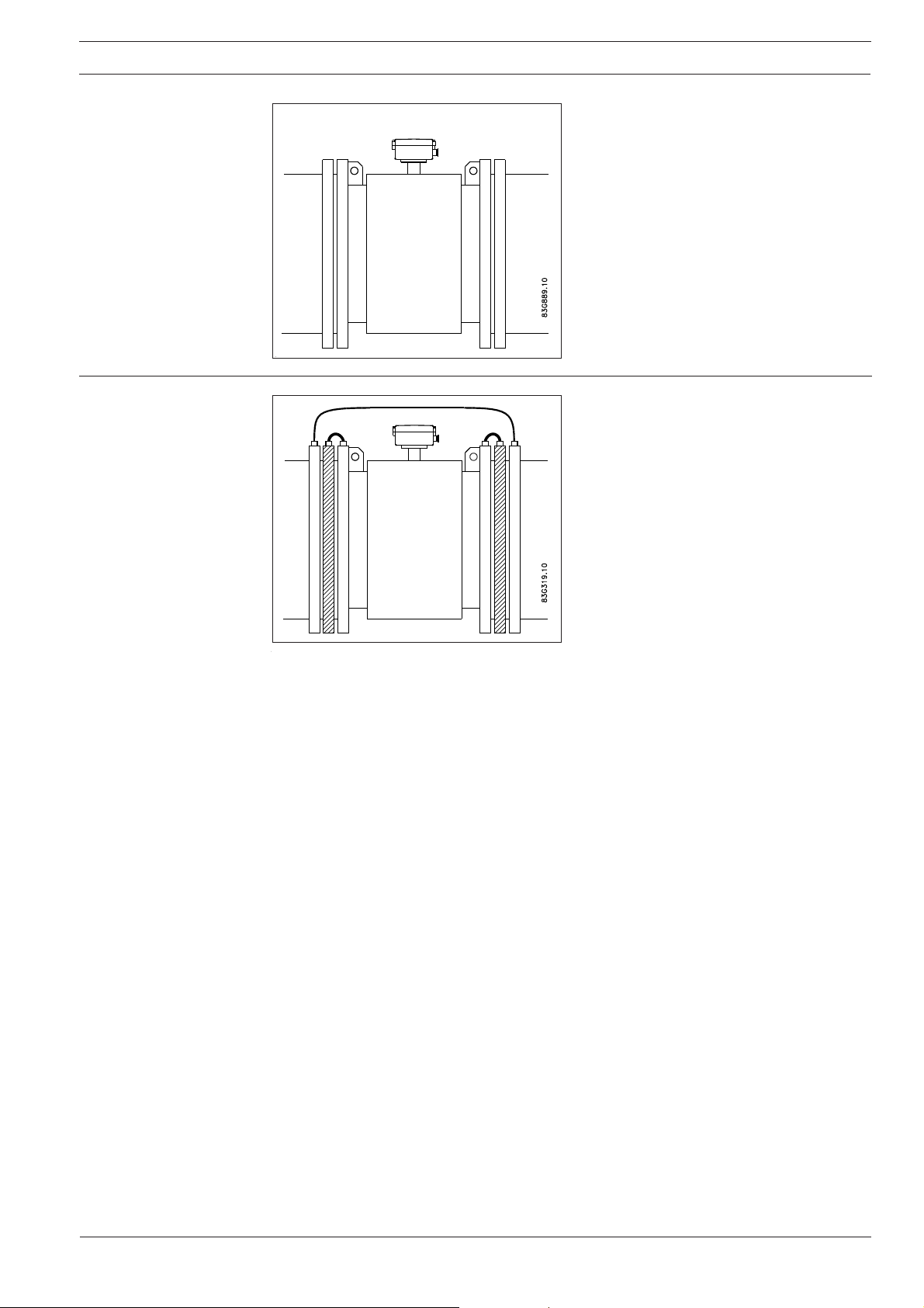
Potential equalisation Potential equalisation is carried out with the
built-in earthing electrodes.
Special attention must be given to systems with
cathodic protection.
By compact mounting:
The transmitter must be supplied through an
isolation transformer. The terminal "PE" must
never be connected.
By remote mounting:
The screen must only be connected at the
sensor end via a 1.5 µF condensator. The
screen must never be connected at both ends.
By isolated sensor:
If above mentioned connections are unaccept-
able the sensor must be isolated from the pipe
work.
Cathodic protected
piping
With earthing electrodes
6
SITRANS F M MAGFLO
Electromagnetic flowmeter type MAG 5100 W
mm inch Nm f/lbs Nm f/lbs Nm f/lbs Nm f/lbs Nm f/lbs
25 1" N/A N/A N/A N/A 10 7 7 5 N/A N/A
40 1½" N/A N/A N/A N/A 16 12 9 7 N/A N/A
50 2" N/A N/A 25 18 N/A N/A 25 18 N/A N/A
65 2½" N/A N/A 25 18 N/A N/A 25 18 N/A N/A
80 3" N/A N/A 25 18 N/A N/A 34 25 N/A N/A
100 4" N/A N/A 25 18 N/A N/A 26 19 N/A N/A
125 5" N/A N/A 29 21 N/A N/A 42 31 N/A N/A
150 6" N/A N/A 50 37 N/A N/A 57 42 N/A N/A
200 8" 50 37 50 37 N/A N/A 88 65 N/A N/A
250 10" 50 37 82 61 N/A N/A 99 73 N/A N/A
300 12" 57 42 111 82 N/A N/A 132 97 N/A N/A
350 14" 60 44 120 89 N/A N/A 225 166 N/A N/A
400 16" 88 65 170 125 N/A N/A 210 155 N/A N/A
450 18" 92 68 170 125 N/A N/A 220 162 N/A N/A
500 20" 103 76 230 170 N/A N/A 200 148 N/A N/A
600 24" 161 119 350 258 N/A N/A 280 207 N/A N/A
700 28" 200 148 304 224 N/A N/A N/A N/A 200 148
750 30" N/A N/A N/A N/A N/A N/A N/A N/A 240 177
800 32" 274 202 386 285 N/A N/A N/A N/A 260 192
900 36" 288 213 408 301 N/A N/A N/A N/A 240 177
1000 40" 382 282 546 403 N/A N/A N/A N/A 280 207
42" N/A N/A N/A N/A N/A N/A N/A N/A 280 207
1100 44" N/A N/A N/A N/A N/A N/A N/A N/A 290 214
1200 48" 395 292 731 539 N/A N/A N/A N/A 310 229
AWWA
Nominal size
PN 10
PN 16 PN 40 Class 150
Maximum allowable
torques
All values are theoretical and are calculated making the following assumptions:
1) All bolts are new and material selection is according to EN 1515-1 table 2
2) Gasket material not exceeding 75 shore A durometer is used between the flowmeter and
mating flanges
3) All bolts are galvanized and adequately lubricated
4) The values are calculated for use with carbon steel flanges
5) Flowmeter and mating flanges are correctly aligned
Torque calculations
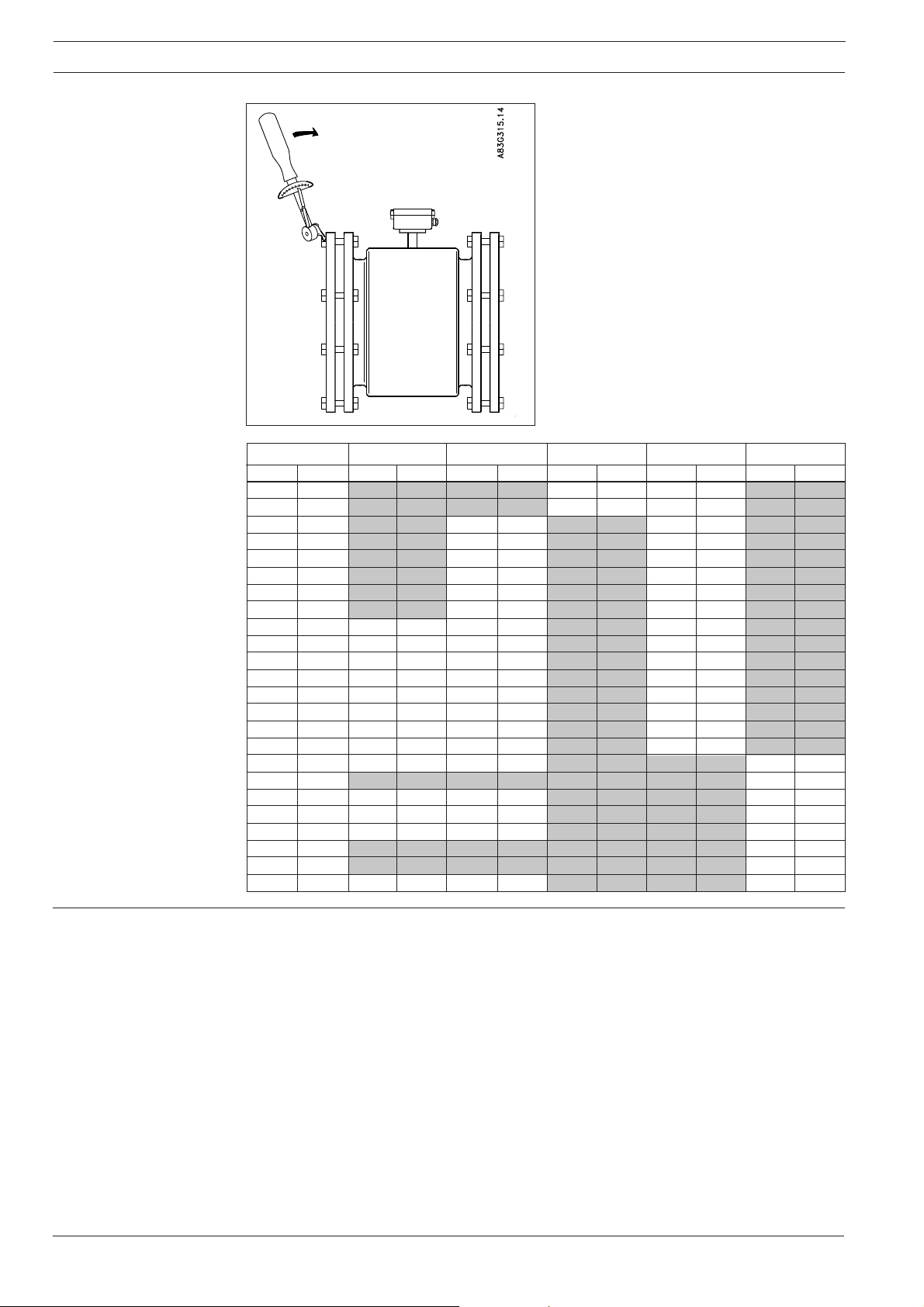
Standard bolts must be well lubricated and tight-
ened evenly around the gasket. Leakage/dam-
age to the flowmeter or piping may arise if bolts
are overtightened.
7
SITRANS F M MAGFLO
Electromagnetic flowmeter type MAG 5100 W
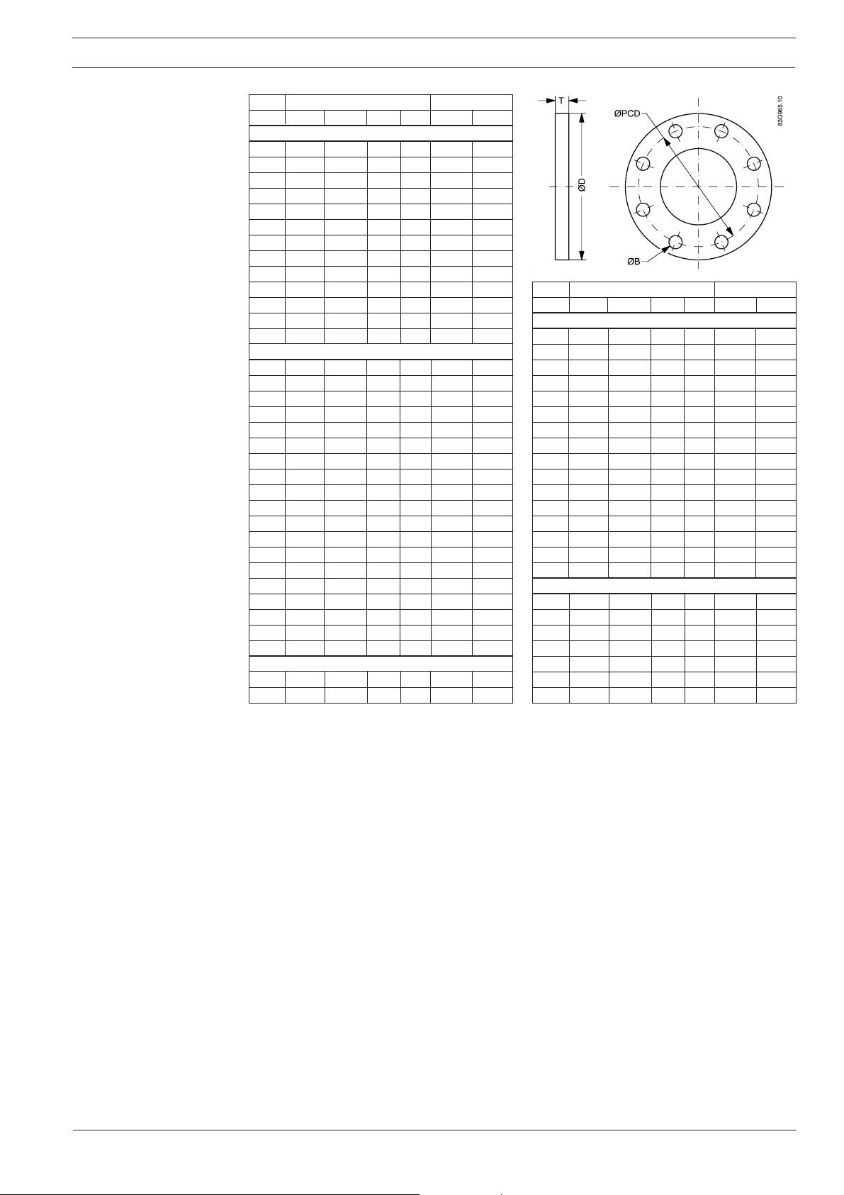
Flange mating dimen-
sions (Metric)
Dimensions mm Bolting
mm OD PCD T B Holes Bolts
PN 10
200 340 295 24 22 8 M20
250 395 350 26 22 12 M20
300 445 400 26 22 12 M20
350 505 460 28 22 16 M20
400 565 515 32 26 16 M24
450 615 565 36 26 20 M24
500 670 620 38 26 20 M24
600 780 725 42 30 20 M27
700 895 840 30 30 24 M27
800 1015 950 32 33 24 M30
900 1115 1050 34 33 28 M30
1000 1230 1160 34 36 28 M33
1200 1455 1380 38 39 32 M36
PN 16
50 165 125 19 18 4 M16
65 185 145 20 18 8 M16
80 200 160 20 18 8 M16
100 220 180 22 18 8 M16
125 250 210 22 18 8 M16
150 285 240 24 22 8 M20
200 340 295 26 22 12 M20
250 405 355 29 26 12 M24
300 460 410 32 26 12 M24
350 520 470 35 26 16 M24
400 580 525 38 30 16 M27
450 640 585 42 30 20 M27
500 715 650 46 33 20 M30
600 840 770 52 36 20 M33
700 910 840 36 36 24 M33
800 1025 950 38 39 24 M36
900 1125 1050 40 39 28 M36
1000 1255 1170 42 42 28 M39
1200 1485 1390 48 48 32 M45
PN 40
25 115 85 16 14 4 M12
40 150 110 18 18 4 M16
Dimensions mm Bolting
mm OD PCD T B Holes Bolts
150 lb
25 108 79 14 16 4 M14
40 127 98 18 16 4 M14
50 152 121 19 19 4 M16
65 178 140 22 19 4 M16
80 190 152 24 19 4 M16
100 229 191 24 19 8 M16
125 254 216 24 22 8 M20
150 279 241 25 22 8 M20
200 343 298 29 22 8 M20
250 406 362 30 25 12 M24
300 483 432 32 25 12 M24
350 533 476 35 28 12 M27
400 597 540 36.5 28 16 M27
450 635 578 40 32 16 M30
500 699 635 43 32 20 M30
600 813 749 48 35 20 M33
AWWA
700 927 864 33 35 28 M33
750 984 914 35 35 28 M33
800 1060 978 38 41 28 M39
900 1168 1086 41 41 32 M39
1000 1289 1200 41 41 36 M39
1050 1346 1257 44 41 36 M39
1200 1511 1422 48 41 44 M39

8
SITRANS F M MAGFLO
Electromagnetic flowmeter type MAG 5100 W
1. Responsibility for the choice of lining and electrode materials with regard to their abrasion and
corrosion resistance lies with the purchaser; the effect of any change in process medium during
the operating life of the flowmeter should be taken into account. Incorrect selection of lining
and/or electrode materials could lead to a failure of the flowmeter.
2. Stresses and loading caused by earthquakes, traffic, high winds and fire damage not taken
into account during flowmeter design.
3. Do not install flowmeter such that it acts as a focus for pipeline stresses. External loadings not
taken into account during flowmeter design.
4. During operation do not exceed the pressure and/or temperature ratings indicated on the data
label or in the installation instructions.
5. It is recommended that all installations should include an appropriate safety valve and
adequate means for draining/venting.
6. Under the Pressure Equipment Directive this product is a pressure accessory, and not
approved for use as a safety accessory, as defined by the Pressure Equipment Directive.
7. Removal of the terminal box except by Siemens Flow Instruments or their approved agents will
invalidate the PED conformity of the product.
In accordance with the Pressure Equipment Directive (97/23/EC).
Manufacturer’s design
and safety statement
We have checked the contents of this manual for agreement with the hardware and
software described. Since deviations cannot be precluded entirely, we cannot guarantee
full agreement. However, the data in this manual are reviewed regularly and any
necessary corrections included in subsequent editions. Suggestions for improvement
are always welcomed.
Technical data subject to change without prior notice.
The reproduction, transmission or use of this document or its contents is not permitted without
express written authority.
Offenders will be liable for damages. All rights, including rights created by patent grant or
registration of a utility model or design, are reserved.
Copyright © Siemens AG 05.2004 All Rights Reserved
Siemens Flow Instruments A/S
Nordborgvej 81
DK-6430 Nordborg
Order no.: FDK:521H1190-01
Printed in: Denmark
INSTRUCTIONS
SITRANS F M MAGFLO
Magnetisch-induktiver Durchflussmesser
Typ MAG 5100 W
DEUTSCH
083R9166
SFIDK.PI.026.V1.52
Siemens Flow Instruments SITRANS F M MAGFLO
magnetisch-induktive Durchflussmesser
bestehen aus einem Messaufnehmer und einem Messumformer. Diese Instruktion beschreibt nur
die Montage des Messaufnehmers. Für weitere Informationen über die Montage des Messumformers,
siehe bitte das SITRANS F M MAGFLO
Produkthandbuch.
Einführung
MAG 5100 W, kompakte/getrennte Montage
Abmessungen und
Gewichte
mm Zoll mm Zoll mm Zoll mm Zoll mm Zoll mm Zoll mm Zoll
25 1" 187 7,4 - - - - 200 7,9 200 7,9 - -
40 1½” 197 7,8 - - - - 200 7,9 200 7,9 - -
50 2" 188 7,4 - - 200 7,9 - - 200 7,9 - -
65 2½” 194 7,6 - - 200 7,9 - - 200 7,9 - -
80 3" 200 7,9 - - 200 7,9 - - 200 7,9 - -
100 4" 207 8,1 - - 250 9,8 - - 250 9,8 - -
125 5" 217 8,5 - - 250 9,8 - - 250 9,8 - -
150 6" 232 9,1 - - 300 11,8 - - 300 11,8 - -
200 8" 257 10,1 350 13,8 350 13,8 - - 350 13,8 - -
250 10" 284 11,2 450 17,7 450 17,7 - - 450 17,7 - -
300 12" 310 12,2 500 19,7 500 19,7 - - 500 19,7 - -
350 14" 362 14,3 550 21,7 550 21,7 - - 550 21,7 - -
400 16" 387 15,2 600 23,6 600 23,6 - - 600 23,6 - -
450 18" 418 16,5 600 23,6 600 23,6 - - 600 23,6 - -
500 20" 443 17,4 625 24,6 625 24,6 - - 680 26,8 - -
600 24" 494 19,4 750 29,5 750 29,5 - - 820 32,3 - -
700 28" 544 21,4 875 34,4 875 34,4 - - - - 875 34,4
750 30" 571 22,5 - - - - - - - - 937 36,9
800 32" 606 23,9 1000 39,4 1000 39,4 - - - - 1000 39,4
900 36" 653 25,7 1125 44,3 1125 44,3 - - - - 1125 44,3
1000 40" 704 27,7 1250 49,2 1250 49,2 - - - - 1250 49,2
42" 704 27,7 - - - - - - - - 1250 49,2
1100 44" 755 29,7 - - - - - - - - 1375 54,1
1200 48" 810 31,9 1500 59,1 1500 59,1 - - - - 1500 59,1
AWWA
Nennweite A
L
PN 10 PN 16 PN 40 Klasse 150
Abmessungen
s
Order no.: FDK:521H1190
10
SITRANS F M MAGFLO
Magnetisch-induktiver Durchflussmesser Typ MAG 5100 W
mmZollkglbkg lbkg lbkg lbkg lb
251"----49 49--
40 1½" - - - - 7 15 6 13 - -
50 2" - - 9 20 - - 8 20 - -
65 2½" - - 10,7 24 - - 11 24 - -
80 3" - - 11,6 26 - - 13 28 - -
100 4" - - 15,2 33 - - 19 41 - -
125 5" - - 20,4 45 - - 24 52 - -
150 6" - - 26 57 - - 29 64 - -
200 8" 48 106 48 106 - - 56 124 - -
250 10" 64 141 69 152 - - 79 174 - -
300 12" 76 167 86 189 - - 110 243 - -
350 14" 100 220 116 255 - - 131 289 - -
400 16" 127 280 144 317 - - 165 364 - -
450 18" 152 335 178 393 - - 176 388 - -
500 20" 184 405 232 512 - - 235 518 - -
600 24" 258 568 343 736 - - 345 761 - -
700 28" 315 693 350 772 - - - - 309 681
750 30" - - - - - - - - 480 1058
800 32" 410 904 442 975 - - - - 421 928
900 36" 512 1129 550 1213 - - - - 539 1188
1000 40" 650 1433 732 1614 - - - - 670 1477
42" - - - - - - - - 700 1544
1100 44" - - - - - - - - 1100 2426
1200 48" 990 2183 1106 2439 - - - - 1030 2271
AWWA
Nennweite
PN 10 PN 16 PN 40 Klasse 150
Gewicht
Auswirkung der
Temperatur auf den
Arbeitsdruck
Metrisch (Drücke in bar)
Nennweite 25 mm, 40 mm und > 300 mm
Flansch- Druck- Temperatur
°°
°°
°C
Spez. stufe −5105090
EN 1092-1 PN 10 10,0 10,0 9,7 9,4
PN 16 16,0 16,0 15,5 15,1
PN 40 40,0 40,0 38,7 37,7
ANSI B16.45 150 lb 19,7 19,7 19,3 18,0
AWWA C-207 Class D 10,3 10,3 10,3 10,3
Nennweite 50 mm bis 300 mm
EN 1092-1 PN 10 10,0 10,0 10,0 8,2
PN 16 10,0 16,0 16,0 13,2
ANSI B16.45 150 lb 10,0 19,7 19,7 16,2
Zollsystem (Drücke in psi)
Nennweite 1", 1½", und > 12"
Flansch- Druck- Temperatur
°°
°°
°F
Spez. stufe 23 50 120 200
EN 1092-1 PN 10 145 145 141 136
PN 16 232 232 225 219
PN 40 580 580 561 547
ANSI B16.45 150 lb 286 286 280 261
AWWA C-207 Class D 150 150 150 150
Nennweite 2" bis 12"
EN 1092-1 PN 10 145 145 145 119
PN 16 145 232 232 191
ANSI B16.45 150 lb 145 286 286 235
 Loading...