


 Loading...
SIMATIC NET
SCALANCE
Industrial Ethernet SCALANCE X-
100 and SCALANCE X-200 Product
Line
Commissioning Manual
1
Preface |
1 |
|
|
|
|
Introduction |
2 |
|
|
|
|
Network Topologies |
3 |
|
|
|
|
Product Characteristics |
4 |
|
|
|
|
Installation and Maintenance |
5 |
|
Diagnostics over Industrial |
|
|
6 |
||
Ethernet |
||
|
|
|
PROFINET IO Functionality |
7 |
|
|
|
|
Notes on the CE Mark |
8 |
|
|
|
|
References |
9 |
|
|
|
|
Dimension Drawings |
10 |
|
|
|

Safety Guidelines
This manual contains notices which you should observe to ensure your own personal safety as well as to avoid property damage. The notices referring to your personal safety are highlighted in the manual by a safety alert symbol, notices referring to property damage only have no safety alert symbol.
Danger
indicates an imminently hazardous situation which, if not avoided, will result in death or serious injury.
Warning
indicates a potentially hazardous situation which, if not avoided, could result in death or serious injury.
Caution
used with the safety alert symbol indicates a potentially hazardous situation which, if not avoided, may result in minor or moderate injury.
Caution
used without safety alert symbol indicates a potentially hazardous situation which, if not avoided, may result in property damage.
Notice
used without the safety alert symbol indicates a potential situation which, if not avoided, may result in an undesirable result or state.
When several danger levels apply, the notices of the highest level (lower number) are always displayed. If a notice refers to personal damages with the safety alert symbol, then another notice may be added warning of property damage.
Qualified Personnel
The device/system may only be set up and operated in conjunction with this documentation. Only qualified personnel should be allowed to install and work on the equipment. Qualified persons are defined as persons who are authorized to commission, to earth, and to tag circuits, equipment and systems in accordance with established safety practices and standards.
Intended Use
Please note the following:
Warning
This device and its components may only be used for the applications described in the catalog or technical description, and only in connection with devices or components from other manufacturers approved or recommended by Siemens.
This product can only function correctly and safely if it is transported, stored, set up and installed correctly, and operated and maintained as recommended.
Trademarks
All designations marked with ® are registered trademarks of Siemens AG. Other designations in this documentation might be trademarks which, if used by third parties for their purposes, might infringe upon the rights of the proprietors.
Copyright Siemens AG, (2004). All rights reserved
Reproduction, transmission or use of this document or its contents is not permitted without express written authority. Offenders will be liable for damages. All rights, including rights created by patent grant or registration of a utility model or design, are reserved.
Disclaimer of Liability
We have checked the contents of this manual for agreement with the hardware and software described. Since deviations cannot be precluded entirely, we cannot guarantee full agreement. However, the data in the manual are reviewed regularly, and any necessary corrections will be included in subsequent editions. Suggestions for improvement are welcomed.
Siemens AG |
|
Automation and Drives Group |
Siemens AG 2004 |
P.O. Box 4848, D-90327 Nuremberg (Germany) |
Technical data subject to change |
|
|
Siemens Aktiengesellschaft |
|
Table of contents
1 |
Preface |
................................................................................................................................................... |
1-1 |
|
1.1 ....................................................................................................................................... |
Preface |
1-1 |
2 |
Introduction............................................................................................................................................. |
2-1 |
|
|
2.1 ................................................................................................................................ |
Introduction |
2-1 |
3 |
Network ................................................................................................................................Topologies |
3-1 |
|
|
3.1 ................................................................................................................... |
Network Topologies |
3-1 |
4 |
Product ...........................................................................................................................Characteristics |
4-1 |
|
|
4.1 ...................................................................................................................... |
SCALANCE X108 |
4-1 |
|
4.1.1 ......................................................................... |
Components of the SCALANCE X108 Product |
4-1 |
|
4.1.2 ........................................................................................................... |
Unpacking and Checking |
4-1 |
|
4.1.3 ................................................................................ |
SCALANCE X108 Product Characteristics |
4-2 |
|
4.1.4 ....................................................................................................... |
SCALANCE X108 TP Ports |
4-3 |
|
4.1.5 .......................................................... |
SCALANCE X108 Power Supply and Signaling Contact |
4-4 |
|
4.1.6 ........................................................................................................... |
SCALANCE X108 Button |
4-5 |
|
4.1.7 ............................................................................................................ |
SCALANCE X108 LEDs |
4-5 |
|
4.1.8 .............................................................................. |
SCALANCE X108 Technical Specifications |
4-6 |
|
4.2 ...................................................................................................................... |
SCALANCE X208 |
4-8 |
|
4.2.1 ....................................................................................... |
Components of the SCALANCE X208 |
4-8 |
|
4.2.2 ........................................................................................................... |
Unpacking and Checking |
4-8 |
|
4.2.3 ....................................................................................... |
SCALANCE X208 Product Properties |
4-9 |
|
4.2.4 ..................................................................................................... |
SCALANCE X208 TP Ports |
4-10 |
|
4.2.5 ........................................................ |
SCALANCE X208 Power Supply and Signaling Contact |
4-11 |
|
4.2.6 ......................................................................................................... |
SCALANCE X208 Button |
4-12 |
|
4.2.7 ............................................................................................... |
C - PLUG Configuration Memory |
4-13 |
|
4.2.8 ...................................................................................................... |
SCALANCE X208 Displays |
4-14 |
|
4.2.9 ............................................................................ |
SCALANCE X208 Technical Specifications |
4-15 |
|
4.3 ............................................................................................................ |
SCALANCE X208PRO |
4-17 |
|
4.3.1 ............................................................................. |
Components of the SCALANCE X208PRO |
4-17 |
|
4.3.2 ......................................................................................................... |
Unpacking and Checking |
4-17 |
|
4.3.3 ............................................................................. |
SCALANCE X208PRO Product Properties |
4-18 |
|
4.3.4 ............................................................................................. |
SCALANCE X208PRO TP Ports |
4-19 |
|
4.3.5 ................................................. |
SCALANCE X208PRO Power Supply and Signaling Contact |
4-20 |
|
4.3.6 ............................................................................................... |
C - PLUG Configuration Memory |
4-21 |
|
4.3.7 .............................................................................................. |
SCALANCE X208PRO Displays |
4-22 |
|
4.3.8 ..................................................................... |
SCALANCE X208PRO Technical Specifications |
4-23 |
|
4.4 ................................................................................................................. |
SCALANCE X206 - 1 |
4-25 |
|
4.4.1 ................................................................................. |
Components of the SCALANCE X206 - 1 |
4-25 |
|
4.4.2 ......................................................................................................... |
Unpacking and Checking |
4-26 |
|
4.4.3 .................................................................................. |
SCALANCE X206 - 1 Product Properties |
4-26 |
|
4.4.4 .................................................................................................. |
SCALANCE X206 - 1 TP Ports |
4-27 |
|
4.4.5 .................................................................................................. |
SCALANCE X206 - 1 FO Ports |
4-28 |
|
4.4.6 ..................................................... |
SCALANCE X206 - 1 Power Supply and Signaling Contact |
4-29 |
Industrial Ethernet SCALANCE X-100 and SCALANCE X-200 Product Line |
iii |
||
Commissioning Manual, 1, |
|||

Table of contents
|
4.4.7 |
SCALANCE X206-1 Button...................................................................................................... |
4-30 |
|
4.4.8 |
C-PLUG Configuration Memory............................................................................................... |
4-31 |
|
4.4.9 |
SCALANCE X206-1 Displays................................................................................................... |
4-32 |
|
4.4.10 |
SCALANCE X206-1 Technical Specifications......................................................................... |
4-33 |
|
4.5 |
SCALANCE X204-2................................................................................................................. |
4-35 |
|
4.5.1 |
Components of the SCALANCE X204-2.................................................................................. |
4-35 |
|
4.5.2 |
Unpacking and Checking......................................................................................................... |
4-36 |
|
4.5.3 |
SCALANCE X204-2 Product Properties.................................................................................. |
4-36 |
|
4.5.4 |
SCALANCE X204-2 TP Ports.................................................................................................. |
4-37 |
|
4.5.5 |
SCALANCE X204-2 FO Ports.................................................................................................. |
4-38 |
|
4.5.6 |
SCALANCE X204-2 Power Supply and Signaling Contact ..................................................... |
4-39 |
|
4.5.7 |
SCALANCE X204-2 Button...................................................................................................... |
4-40 |
|
4.5.8 |
C-PLUG Configuration Memory............................................................................................... |
4-41 |
|
4.5.9 |
SCALANCE X204-2 Displays................................................................................................... |
4-42 |
|
4.5.10 |
SCALANCE X204-2 Technical Specifications......................................................................... |
4-43 |
5 |
Installation and Maintenance.................................................................................................................. |
5-1 |
|
|
5.1 |
Installation.................................................................................................................................. |
5-1 |
|
5.2 |
Installation on a DIN Rail............................................................................................................ |
5-1 |
|
5.3 |
Installation on a Standard Rail................................................................................................... |
5-3 |
|
5.4 |
Wall Mounting ............................................................................................................................ |
5-4 |
|
5.5 |
Grounding................................................................................................................................... |
5-5 |
|
5.6 |
Fitting the IE FC RJ-45 Plug 180............................................................................................... |
5-5 |
|
5.7 |
Maintenance............................................................................................................................... |
5-8 |
6 |
Diagnostics over Industrial Ethernet ....................................................................................................... |
6-1 |
|
|
6.1 |
Configuration with the Primary Setup Tool ................................................................................ |
6-1 |
|
6.1.1 |
Introduction ................................................................................................................................ |
6-1 |
|
6.1.2 |
Installing the Primary Setup Tool............................................................................................... |
6-1 |
|
6.1.3 |
The DLC Protocol....................................................................................................................... |
6-2 |
|
6.1.4 |
Installing the DLC Protocol......................................................................................................... |
6-3 |
|
6.1.5 |
Working with the Primary Setup Tool......................................................................................... |
6-4 |
|
6.1.6 |
Configuring a Module................................................................................................................. |
6-4 |
|
6.2 |
Web Based Management (WBM).............................................................................................. |
6-8 |
|
6.2.1 |
General Information on Web Based Management .................................................................... |
6-8 |
|
6.2.2 |
Requirements for Web Based Management.............................................................................. |
6-8 |
|
6.2.3 |
Access over WBM...................................................................................................................... |
6-9 |
|
6.2.4 |
WBM Menus............................................................................................................................. |
6-10 |
|
6.2.4.1 |
Management Menus - The Start Menu.................................................................................... |
6-10 |
|
6.2.4.2 |
The "System Configuration" WBM Menu................................................................................. |
6-11 |
|
6.2.4.3 |
The "System Restart & Defaults" WBM Menu......................................................................... |
6-13 |
|
6.2.4.4 |
The "System Save & Load HTTP" WBM Menu ....................................................................... |
6-14 |
|
6.2.4.5 |
The "System Save & Load TFTP" WBM Menu........................................................................ |
6-15 |
|
6.2.4.6 |
The "System Version Numbers" WBM Menu........................................................................... |
6-16 |
|
6.2.4.7 |
The "System Passwords" WBM Menu..................................................................................... |
6-17 |
|
6.2.4.8 |
The "Status" WBM Menu ......................................................................................................... |
6-17 |
|
6.2.4.9 |
The "Fault Mask" WBM Menu.................................................................................................. |
6-18 |
|
6.2.4.10 |
The "Ring Redundancy" WBM Menu....................................................................................... |
6-19 |
|
6.2.4.11 |
The "C-PLUG Information" WBM Menu................................................................................... |
6-20 |
|
6.2.4.12 |
The "Agent Configuration" WBM Menu.................................................................................... |
6-20 |
|
6.2.4.13 |
The "Agent Event Configuration" WBM Menu ......................................................................... |
6-21 |
|
6.2.4.14 |
The "Agent E-Mail Configuration" WBM Menu ........................................................................ |
6-23 |
|
6.2.4.15 |
The "Agent SNMP Configuration" WBM Menu........................................................................ |
6-24 |
iv |
|
Industrial Ethernet SCALANCE X-100 and SCALANCE X-200 Product Line |
|
|
|
Commissioning Manual, 1, |
|
|
|
|
Table of contents |
|
6.2.4.16 |
The "Agent Trap Configuration" WBM Menu........................................................................... |
6-25 |
|
6.2.4.17 |
The "Switch Configuration (Port Mirroring)" WBM Menu......................................................... |
6-26 |
|
6.2.4.18 |
The "Switch Ports Status" WBM Menu.................................................................................... |
6-26 |
|
6.2.4.19 |
The "Switch Port Diagnostics" WBM Menu ............................................................................. |
6-28 |
|
6.2.4.20 |
The "Statistics" WBM Menu..................................................................................................... |
6-29 |
|
6.2.4.21 |
The "Packet Size Statistic" WBM Menu................................................................................... |
6-30 |
|
6.2.4.22 |
The "Packet Type Statistic" WBM Menu.................................................................................. |
6-31 |
|
6.2.4.23 |
The "Packet Error Statistic" WBM Menu.................................................................................. |
6-32 |
7 |
PROFINET IO Functionality.................................................................................................................... |
7-1 |
|
|
7.1 |
Configuring with PROFINET IO................................................................................................. |
7-1 |
8 |
Notes on the CE Mark ............................................................................................................................ |
8-1 |
|
|
8.1 |
Notes on the CE Mark................................................................................................................ |
8-1 |
9 |
References............................................................................................................................................. |
9-1 |
|
|
9.1 |
References................................................................................................................................. |
9-1 |
10 |
Dimension Drawings............................................................................................................................. |
10-1 |
|
|
10.1 |
Dimension Drawing.................................................................................................................. |
10-1 |
|
Index |
|
|
Industrial Ethernet SCALANCE X-100 and SCALANCE X-200 Product Line |
v |
Commissioning Manual, 1, |
Preface |
1 |
1.1Preface
Purpose of the Commissioning Manual
This commissioning manual supports you when commissioning networks with the devices of the product line SCALANCE X-100 and X-200.
Validity of this Commissioning Manual
This commissioning manual is valid for the following devices:
SIMATIC NET SCALANCE X108 6GK5108-0BA00-2AA3
SIMATIC NET SCALANCE X208 6GK5208-0BA00-2AA3
SIMATIC NET SCALANCE X208PRO 6GK5208-0CA00-2AA6
SIMATIC NET SCALANCE X204-2 6GK5204-2BB00-2AA3
SIMATIC NET SCALANCE X206-1 6GK5206-1BB00-2AA3
Further Documentation
The "SIMATIC NET Industrial Ethernet Twisted Pair and Fiber Optic Networks“ manual contains additional information on other SIMATIC NET products that you can operate along with the devices of the SCALANCE X-100 and X-200 product lines in an Industrial Ethernet network.
Finding Information
To help you to find the information you require more quickly, the manual includes not only the table of contents but also the following sections in the Appendix:
• Index
Audience
This commissioning manual is intended for persons involved in commissioning networks with the devices of the SCALANCE X-100 and X-200 product lines.
Industrial Ethernet SCALANCE X-100 and SCALANCE X-200 Product Line |
1-1 |
Commissioning Manual, 1, |

Preface
1.1 Preface
Standards and Approvals
The devices of the SCALANCE X-100 and X-200 product lines meet the requirements for the CE mark. You will find detailed information in the section "Notes on CE Marking" in this commissioning manual.
1-2 |
Industrial Ethernet SCALANCE X-100 and SCALANCE X-200 Product Line |
Commissioning Manual, 1, |

Introduction |
2 |
2.1Introduction
This chapter provides you with an overview of the functions of the Industrial Ethernet switches of the SCALANCE X-100 and X-200 product lines.
The devices of the SCALANCE X-100 are unmanaged Industrial Ethernet switches with up to eight ports and on-site diagnostics for applications in the vicinity of the machinery.
The devices of the SCALANCE X-200 are managed Industrial Ethernet switches that can be used universally for applications ranging from those in the vicinity of the machinery to networked units. Configuration engineering and remote diagnostics are integrated in the SIMATIC STEP 7 engineering tool increasing the plant availability. Devices with a high degree of protection allow installation without a cabinet.
What Is Possible?
The devices of the SCALANCE X-100 or SCALANCE X-200 product lines, allow the costeffective installation of Industrial Ethernet bus, star, or ring structures with switching functionality.
Note
When using devices of the SCALANCE X-100 product line in a redundant ring, the redundancy function is not supported.
Note
The requirements of EN61000-4-5, surge test on power supply lines are met only when a Blitzductor VT AD 24V type no. 918 402 is used
Manufacturer:
DEHN+SÖHNE GmbH+Co.KG Hans Dehn Str.1 Postfach 1640 D-92306 Neumarkt, Germany
Industrial Ethernet SCALANCE X-100 and SCALANCE X-200 Product Line |
2-1 |
Commissioning Manual, 1, |

Introduction
2.1 Introduction
Warning
When used under hazardous conditions (zone 2), the devices of the SCALANCE X-100 and SCALANCE X-200 product lines must be installed in an enclosure.
To comply with ATEX100a (EN 50021), this enclosure must meet the requirements of at least IP54 in compliance with EN 60529.
WARNING - EXPLOSION HAZARD: DO NOT CONNECT OR DISCONNECT EQUIPMENT UNLESS AREA IS KNOWN TO BE NONHAZARDOUS.
Note
The specified approvals apply only when the corresponding mark is printed on the product.
2-2 |
Industrial Ethernet SCALANCE X-100 and SCALANCE X-200 Product Line |
Commissioning Manual, 1, |
Network Topologies |
3 |
3.1Network Topologies
Switching technology allows extensive networks to be set up with numerous nodes and simplifies network expansion.
Which topologies can be implemented?
Bus, ring, or star topologies can be implemented with the devices of the SCALANCE X-100 or SCALANCE X-200 product lines.
Bus Topology
Figure 3-1 Bus Topology, Example with SCALANCE X108
Industrial Ethernet SCALANCE X-100 and SCALANCE X-200 Product Line |
3-1 |
Commissioning Manual, 1, |

Network Topologies
3.1 Network Topologies
Star Topology
Figure 3-2 Electrical Star Topology, Example with SCALANCE X108
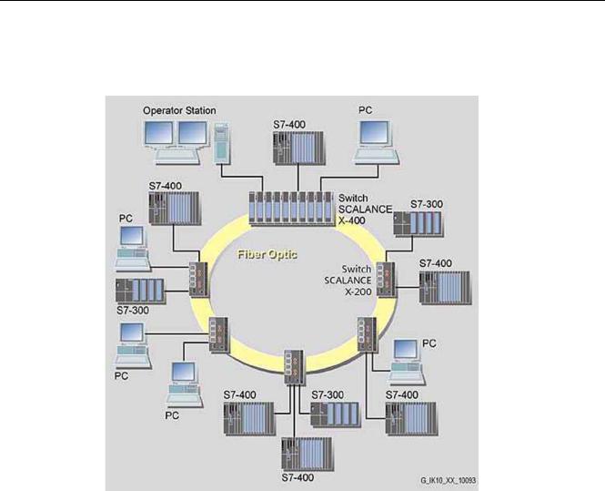
Figure 3-3 Optical Star Topology, Example with SCALANCE X-400 and SCALANCE X206-1
3-2 |
Industrial Ethernet SCALANCE X-100 and SCALANCE X-200 Product Line |
Commissioning Manual, 1, |
Network Topologies
3.1 Network Topologies
Ring Topology
Figure 3-4 Ring Topology, Example with SCALANCE X204-2 and SCALANCE X-400 as
Redundancy Manager
To increase availability, optical or electrical bus topologies made up of SCALANCE X-200 switches with a SCALANCE X414-3E, OSM version 2, or ESM version 2 configured as a redundancy manager can be closed to form a ring. The SCALANCE X-200 switches are first connected over their ring ports to form a bus. The two ends of the bus are closed to form a ring by a SCALANCE X414-3E or OSM / ESM operating in the redundancy manager mode. In contrast to the ring ports of the SCALANCE X-200 switches, the ring ports of the redundancy manager are disconnected from each other during problem-free network operation.
The SCALANCE X414-3E or OSM / ESM operating in the redundancy manager mode monitors the connected bus over its ring ports and switches the ring ports through if there is an interruption on the connected bus; in other words, it restores a functioning bus over this substitute path. Reconfiguration takes place within 0.3 s.
As soon as the problem has been eliminated, the original topology is restored; in other words, the ring ports in the redundancy manager are once again disconnected from each other.
Industrial Ethernet SCALANCE X-100 and SCALANCE X-200 Product Line |
3-3 |
Commissioning Manual, 1, |

Product Characteristics |
4 |
4.1SCALANCE X108
4.1.1Components of the SCALANCE X108 Product
What ships with the SCALANCE X108?
•SCALANCE X108 device
•2-pin plug-in terminal block
•4-pin plug-in terminal block
•Product information
•CD
–Commissioning Manual
–PST Tool (only for devices of the SCALANCE X-200 product line)
4.1.2Unpacking and Checking
Unpacking, Checking
1.Make sure that the package is complete.
2.Check all the parts for transport damage.
Warning
Do not use any parts that show evidence of damage!
Industrial Ethernet SCALANCE X-100 and SCALANCE X-200 Product Line |
4-1 |
Commissioning Manual, 1, |
Product Characteristics
4.1 SCALANCE X108
Warning
If the SCALANCE X108 device is operated in ambient temperatures between 65°C and 70°C, the temperature of the device housing may be higher than 70°C.
The subject unit must be located in a Restricted Access Location where access can only be gained by SERVICE PERSONNEL or by USERS who have been instructed about the reasons for the restrictions applied to the location and about any precautions that shall be taken when operated in an ambient air temperature of 65-70°C.
4.1.3SCALANCE X108 Product Characteristics
Possible Attachments
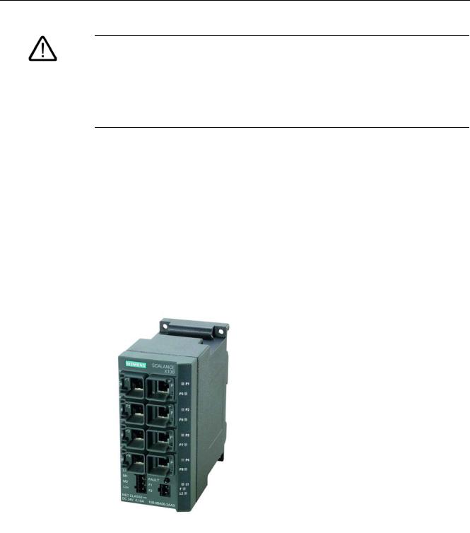
The SCALANCE X108 has eight RJ-45 jacks for the connection of end devices or other network segments.
Figure 4-1 SCALANCE X108
4-2 |
Industrial Ethernet SCALANCE X-100 and SCALANCE X-200 Product Line |
Commissioning Manual, 1, |

Product Characteristics
4.1 SCALANCE X108
4.1.4SCALANCE X108 TP Ports
Connector Pinout
On the SCALANCE X108, the twisted-pair ports are implemented as RJ-45 jacks with MDI-X assignment (Medium Dependent Interface–Autocrossover) of a network component.
Notice
TP cords or TP-XP cords with a maximum length of 10 m can be connected to the RJ-45 TP port.
With the IE FC cables and IE FC RJ-45 plug 180, an overall cable length of a maximum of 100 m is permitted between two devices.
Autonegotiation
Autonegotiation means the automatic detection of the functionality of the port at the opposite end. Using autonegotiation, repeaters or DTEs can detect the functionality available at the port of a partner device allowing automatic configuration of different types of device. With autonegotiation, two components connected to a link segment can exchange parameters and set themselves to match the supported communication functionality.
Note
Devices not supporting autonegotiation must be set to 100 Mbps/ half duplex or 10 Mbps half duplex.
Note
The SCALANCE X108 is a plug and play device that does not require settings to be made for commissioning.
MDI /MDIX Autocrossover Function
The advantage of the MDI /MDIX autocrossover function is that straight-through cables can be used throughout and crossover Ethernet cables are unnecessary. This prevents malfunctions resulting from mismatching send and receive wires. This makes installation much easier for the user.
The devices of the SCALANCE X-100 and X-200 product lines all support the MDI / MDIX autocrossover function.
Industrial Ethernet SCALANCE X-100 and SCALANCE X-200 Product Line |
4-3 |
Commissioning Manual, 1, |

Product Characteristics
4.1 SCALANCE X108
4.1.5SCALANCE X108 Power Supply and Signaling Contact
Power Supply
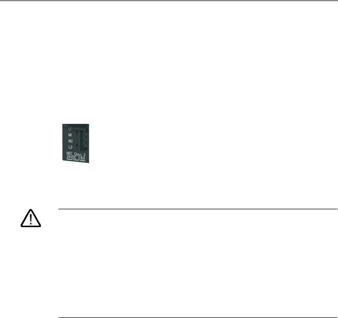
The power supply is connected using a 4-pin plug-in terminal block. The power supply can be connected redundantly. Both inputs are isolated. There is no distribution of load. When a redundant power supply is used, the power supply unit with the higher output voltage supplies the SCALANCE X108 alone. The power supply is connected over a high resistance with the enclosure to allow an ungrounded set up.
Figure 4-2 SCALANCE X108 Power Supply
Warning
The SCALANCE X108 is designed for operation with safety extra-low voltage. This means that only safety extra-low voltages (SELV) complying with IEC950/EN60950/ VDE0805 can be connected to the power supply terminals.
The power supply unit to supply the SCALANCE W108 must comply with NEC Class 2 (voltage range 18 - 32 V, current requirement 350 mA)
If the device is connected to a redundant power supply (two separate power supplies), both must meet these requirements.
The signaling contact can be subjected to a maximum load of 100 mA (safety extra-low voltage (SELV), DC 24 V).
Never connect the SCALANCE X108 to AC voltage or DC voltage higher than 32 V DC.
Signaling Contact
The signaling contact is connected to a 2-pin plug-in terminal block. The signaling contact is a floating switch with which error/fault states can be signaled by breaking the contact.
The following errors/faults can be signaled by the signaling contact:
•The failure of a link at a monitored port.
•The failure of one of the two redundant power supplies.
The connection or disconnection of a communication node on an unmonitored port does not lead to an error message.
The signaling contact remains activated until the error/fault is eliminated or until the current status is applied as the new desired status using the button.
4-4 |
Industrial Ethernet SCALANCE X-100 and SCALANCE X-200 Product Line |
Commissioning Manual, 1, |

Product Characteristics
4.1 SCALANCE X108
When the device is turned off, the signaling contact is always activated (open).
Figure 4-3 Signaling Contact SCALANCE X108
4.1.6SCALANCE X108 Button
What does the button do?
Using the button, you can display and modify the set fault mask.
After pressing the button, the currently valid fault mask is displayed for approximately 3 seconds. The LEDs of the monitored ports flash at a frequency of 5 Hz.
After 3 seconds the new fault mask is displayed. The flashing frequency is reduced to 2.5 Hz. After a further 3 seconds, the new fault mask is adopted and saved. The monitored ports are indicated by permanently lit LEDs until the button is released.
As long as the LEDs are still flashing, the saving of the mask can be interrupted by releasing the button.
If an empty fault mask is set (no port is monitored) or you want to set an empty mask, four 4 LEDs flash on and off alternating with their neighboring LEDs.
At the same time, you can also set the monitoring of the redundant power supply with the fault mask. Monitoring of the power supply is activated only when both power supplies are connected when the fault mask is saved.
The factory default is no port monitoring.
4.1.7SCALANCE X108 LEDs
Fault indicator (red LED)
Status |
Meaning |
|
lit red |
The SCALANCE X108 detects an error. At the same time, the |
|
|
signaling contact opens. |
|
|
The following faults are detected: |
|
|
1. |
Link down event on a monitored port |
|
2. |
Failure of one of the two redundant power supplies. |
not lit |
No fault detected by the SCALANCE X108. |
|
Industrial Ethernet SCALANCE X-100 and SCALANCE X-200 Product Line |
4-5 |
Commissioning Manual, 1, |

Product Characteristics
4.1 SCALANCE X108
Power indicator (green LED)
The status of the power supply is indicated by two green LEDs:
Status |
Meaning |
lit green |
Power supply L1 or L2 is connected. |
not lit |
Power supply L+ is not connected or <14 V |
Port status indicator (green/yellow LEDs)
The status of the ports is indicated by eight LEDs:
Status |
|
Meaning |
Port 1 through 8 |
LED lit green |
TP link exists, no data reception |
Port 1 through 8 |
LED lit yellow |
TP link exists, data received at TP port |
Ports 1 through 8 LED flash yellow |
Setting or display of the fault mask |
|
4.1.8 |
SCALANCE X108 Technical Specifications |
|
|
Technical Specifications of the SCALANCE X108 |
|
||
|
|
|
|
|
|
Ports |
|
|
|
Attachment of DTEs or network components over |
8 x RJ-45 sockets with MDI-X pinning 10/100 |
|
|
twisted pair |
Mbps (half/ full duplex) |
|
|
Connector for power supply |
1 x 4-pin plug-in terminal block |
|
|
Connector for signaling contact |
1 x 2-pin plug-in terminal block |
|
|
Electrical Data |
|
|
|
Power supply |
2 x 24 V DC |
|
|
|
(18 - 32 V DC) |
|
|
|
safety extra-low voltage (SELV) |
|
|
Power loss at DC 24 V |
3.36 W |
|
|
Current consumption at rated voltage |
140 mA |
|
|
Overvoltage protection at input |
PTC resetable fuse (0.6 A / 60 V) |
|
|
Permitted Cable Lengths |
|
|
|
Network span parameter/TP cable length |
|
|
|
0 – 100 m |
IE FC standard cable with IE FC RJ-45 plug 180 |
|
|
|
or |
|
|
|
over IE FC outlet RJ-45 with 0 - 90 m IE FC |
|
|
|
standard cable + 10 m TP cord |
|
|
0 – 85 m |
IE FC marine/trailing cable with IE FC RJ-45 plug |
|
|
|
180 |
|
|
|
or |
|
|
|
0 - 75 m IE FC marine/trailing cable + 10 m TP |
4-6 |
Industrial Ethernet SCALANCE X-100 and SCALANCE X-200 Product Line |
Commissioning Manual, 1, |
Product Characteristics
4.1 SCALANCE X108
|
|
|
cord |
Aging time |
|
Aging time |
5 minutes |
|
|
Permitted Environmental Conditions / EMC |
|
Operating temperature |
-20° C through +70° C |
Storage/transport temperature |
-40° C through +80° C |
Relative humidity in operation |
‹ 95% (no condensation) |
Operating altitude |
2000 m at max 56 °C ambient temperature |
|
3000 m at max. 50 °C ambient temperature |
RF interference level |
EN 50081-2 Class A |
Noise immunity |
EN 50082-2 |
Degree of protection |
Tested to IP30 |
Approvals |
|
c-UL-us |
UL 60950 |
|
CSA C22.2 No. 60950 |
c-Ul-us for hazardous locations |
UL 1604, UL 2279Pt.15 |
FM |
FM 3611 |
C-TICK |
AS/NZS 2064 (Class A). |
CE |
EN 50081-2, EN 50082-2 |
ATEX Zone 2 |
EN50021 |
MTBF |
|
MTBF |
37.08 years |
Construction |
|
Dimensions (W x H x D) in mm |
60 x 125 x 124 |
Weight in g |
780 |
Installation options |
DIN rail |
|
S7-300 standard rail |
|
Wall Mounting |
Order Numbers |
|
SCALANCE X108 |
6GK5108-0BA00-2AA3 |
"Industrial Ethernet TP and Fiber Optic Networks" |
6GK1970-1BA10-0AA0 |
manual |
|
IE FC Stripping Tool |
6GK1901-1GA00 |
IE FC blade cassettes |
6GK1901-1GB00 |
IE FC TP standard cable |
6XV1840 2AH10 |
IE FC TP trailing cable |
6XV1840-3AH10 |
IE FC TP marine cable |
6XV1840-4AH10 |
IE FC RJ-45 Plug 180 pack of 1 |
6GK1 901-1BB10-2AA0 |
IE FC RJ-45 Plug 180 pack of 10 |
6GK1 901-1BB10-2AB0 |
IE FC RJ-45 Plug 180 pack of 50 |
6GK1 901-1BB10-2AE0 |
Industrial Ethernet SCALANCE X-100 and SCALANCE X-200 Product Line |
4-7 |
Commissioning Manual, 1, |

Product Characteristics
4.2 SCALANCE X208
Note
The number of connected SCALANCE X Industrial Ethernet Switches influences the frame propagation time.
When a frame passes through the devices of the SCALANCE X-100 and/or SCALANCE X- 200 product lines, it is delayed by the store and forward function of the switch:
-with a 64 byte frame length by approx. 10 µs (at 100 Mbps)
-with a 1500 byte frame length by approx. 130 µs (at 100 Mbps)
This means that the more devices of the SCALANCE X-100 and/or SCALANCE X-200 product lines that a frame passes through, the higher the frame propagation time will be.
4.2SCALANCE X208
4.2.1Components of the SCALANCE X208
What ships with the SCALANCE X208?
•SCALANCE X208 Device
•2-pin plug-in terminal block
•4-pin plug-in terminal block
•Product information
•CD
–Commissioning Manual
–PST Tool
4.2.2Unpacking and Checking
Unpacking, Checking
1.Make sure that the package is complete.
2.Check all the parts for transport damage.
Warning
Do not use any parts that show evidence of damage!
4-8 |
Industrial Ethernet SCALANCE X-100 and SCALANCE X-200 Product Line |
Commissioning Manual, 1, |

Product Characteristics
4.2 SCALANCE X208
Warning
If the SCALANCE X208 device is operated in ambient temperatures between 65°C and 70°C, the temperature of the device housing may be higher than 70°C.
The subject unit must be located in a Restricted Access Location where access can only be gained by SERVICE PERSONNEL or by USERS who have been instructed about the reasons for the restrictions applied to the location and about any precautions that shall be taken when operated in an ambient air temperature of 65-70°C.
4.2.3SCALANCE X208 Product Properties
Possible Attachments
The SCALANCE X208 has eight RJ-45 jacks for the connection of end devices or other network segments.
Figure 4-4 SCALANCE X208
Industrial Ethernet SCALANCE X-100 and SCALANCE X-200 Product Line |
4-9 |
Commissioning Manual, 1, |

Product Characteristics
4.2 SCALANCE X208
4.2.4SCALANCE X208 TP Ports
Connector Pinout
On the SCALANCE X208, the TP ports are implemented as RJ-45 sockets with MDI-X assignment (Medium Dependent Interface–Autocrossover) of a network component.
Notice
TP cords or TP-XP cords with a maximum length of 10 m can be connected to the RJ-45 TP port.
With the IE FC cables and IE FC RJ-45 plug 180, an overall cable length of a maximum of 100 m is permitted between two devices.
Autonegotiation
Autonegotiation means the automatic detection of the functionality of the port at the opposite end. Using autonegotiation, repeaters or DTEs can detect the functionality available at the port of a partner device allowing automatic configuration of different types of device. With autonegotiation, two components connected to a link segment can exchange parameters and set themselves to match the supported communication functionality.
Note
Devices not supporting autonegotiation must be set to 100 Mbps/ half duplex or 10 Mbps half duplex.
Note
The SCALANCE X208 is a plug-and-play device that does not require settings to be made for commissioning.
MDI /MDIX Autocrossover Function
The advantage of the MDI /MDIX autocrossover function is that straight-through cables can be used throughout and crossover Ethernet cables are unnecessary. This prevents malfunctions resulting from mismatching send and receive wires. This makes installation much easier for the user.
The devices of the SCALANCE X-100 and X-200 product lines all support the MDI / MDIX autocrossover function.
4-10 |
Industrial Ethernet SCALANCE X-100 and SCALANCE X-200 Product Line |
Commissioning Manual, 1, |
Product Characteristics
4.2 SCALANCE X208
4.2.5SCALANCE X208 Power Supply and Signaling Contact
Power Supply
The power supply is connected using a 4-pin plug-in terminal block. The power supply can be connected redundantly. Both inputs are isolated. There is no distribution of load. When a redundant power supply is used, the power supply unit with the higher output voltage supplies the SCALANCE X208 alone. The power supply is connected over a high resistance with the enclosure to allow an ungrounded set up.
Figure 4-5 SCALANCE X208 Power Supply
Warning
The SCALANCE X208 is designed for operation with safety extra-low voltage. This means that only safety extra-low voltages (SELV) complying with IEC950/EN60950/ VDE0805 can be connected to the power supply terminals.
The power supply unit to supply the SCALANCE X208 must comply with NEC Class 2 (voltage range 18 - 32 V, current requirement 350 mA)
If the device is connected to a redundant power supply (two separate power supplies), both must meet these requirements.
The signaling contact can be subjected to a maximum load of 100 mA (safety extra-low voltage (SELV), DC 24 V).
Never connect the SCALANCE X208 to AC voltage or DC voltage higher than 32 V DC.
Signaling Contact
The signaling contact is connected to a 2-pin plug-in terminal block. The signaling contact (relay contact) is a floating switch with which error/fault states can be signaled by breaking the contact.
Industrial Ethernet SCALANCE X-100 and SCALANCE X-200 Product Line |
4-11 |
Commissioning Manual, 1, |

Product Characteristics
4.2 SCALANCE X208
Figure 4-6 SCALANCE X208 Signaling Contact
The following errors/faults can be signaled by the signaling contact:
•The failure of a link at a monitored port.
•The failure of one of the two redundant power supplies.
The connection or disconnection of a communication node on an unmonitored port does not lead to an error message.
The signaling contact remains activated until the error/fault is eliminated or until the current status is applied as the new desired status using the button.
When the device is turned off, the signaling contact is always activated (open).
4.2.6SCALANCE X208 Button
What does the button do?
Using the button, you can display and modify the set fault mask.
After pressing the button, the currently valid fault mask is displayed for approximately 3 seconds. The monitored ports flash at a frequency of 5 Hz.
After 3 seconds the new fault mask is displayed. The flashing frequency is reduced to 2.5 Hz. After a further 3 seconds, the new fault mask is adopted and saved. The monitored ports are indicated by permanently lit LEDs until the button is released.
As long as the LEDs are still flashing, the saving of the mask can be interrupted by releasing the button.
If an empty fault mask is set (no port is monitored) or you want to set an empty mask, four 4 LEDs flash on and off alternating with their neighboring LEDs.
At the same time, you can also set the monitoring of the redundant power supply with the fault mask. Monitoring of the power supply is activated only when both power supplies are connected when the fault mask is saved.
The factory default is no port monitoring.
If the button is pressed longer (15 seconds), the device is reset to "factory defaults". This is indicated by all the Port LEDs flashing. During this activity, the device must not be turned off.
4-12 |
Industrial Ethernet SCALANCE X-100 and SCALANCE X-200 Product Line |
Commissioning Manual, 1, |

Product Characteristics
4.2 SCALANCE X208
4.2.7C-PLUG Configuration Memory
Area of Application
The C-PLUG is an exchangeable medium for storage of the configuration and project engineering data of the basic device. This means that the configuration data remains available if the basic device is replaced.
How It Works
Power is supplied by the end device. The C-PLUG retains all data permanently when the power is turned off.
If an empty C-PLUG (factory settings) is inserted, all configuration data of the SCALANCE X- 200 is saved to it when the device starts up. Changes to the configuration during operation are also saved on the C-PLUG without any operator intervention being necessary.
A basic device with an inserted C-PLUG automatically uses the configuration data of the C- PLUG when it starts up. This is, however, only possible when the data was written by a compatible device type.
This allows fast and simple replacement of the basic device. If a device is replaced, the C- PLUG is taken from the failed component and inserted in the replacement. The first time it is started up, the replacement device has the same configuration as the failed device except for the MAC address set by the vendor.
Using a Previously Written C-PLUG
If you want to insert a C-PLUG that has already been written to in a new basic device requiring a different configuration, you must format the C-PLUG using the delete function in Web Based Management following device startup. If the C-PLUG was written by an incompatible device type, the basic device will not start up fully and signals an error. The delete function can nevertheless be used. When the device next starts up, the current configuration data of the basic device is written to the C-PLUG.
Diagnostics
Inserting a C-PLUG that does not contain the configuration of a compatible device type, inadvertently removing the C-PLUG, or general malfunctions of the C-PLUG are indicated by the diagnostic mechanisms of the switch (LEDs, PROFINET, SNMP, WBM, etc.).
Inserting in the C-PLUG Slot
The C-PLUG is not supplied with the devices of the SCALANCE X-200 product line. It is available as an optional accessory.
The slot for the C-PLUG is located on the back of the device.
To insert the C-PLUG, remove the screw cover. The C-PLUG is inserted in the receptacle. The screw cover must then be closed correctly.
Industrial Ethernet SCALANCE X-100 and SCALANCE X-200 Product Line |
4-13 |
Commissioning Manual, 1, |

Product Characteristics
4.2 SCALANCE X208
Notice
The C-PLUG may only be inserted or removed when the power is off!
Removing the C-PLUG
It is only necessary to remove the C-PLUG if the basic device develops a fault.
The C-PLUG can be removed from the slot using flat pliers, tweezers, or a small screwdriver.
4.2.8SCALANCE X208 Displays
Fault indicator (red LED)
Status |
Meaning |
|
lit red |
The SCALANCE X208 detects an error. At the same time, the |
|
|
signaling contact opens. |
|
|
The following faults are detected: |
|
|
1. |
Link down event on a monitored port |
|
2. |
Failure of one of the two redundant power supplies. |
|
3. |
Device startup, the LED is lit for approx. 20s. |
flashes red |
An internal fault was detected. |
|
|
Notify the maintenance personnel and, if necessary, send the |
|
|
device in for repair. |
|
not lit |
No fault detected by the SCALANCE X208. |
|
Power indicator (green LED)
The status of the power supply is indicated by two green LEDs:
Status |
Meaning |
lit green |
Power supply L1 or L2 is connected. |
not lit |
Power supply L1 and/or L2 not connected or <14 V. |
Port status indicator (green/yellow LEDs)
The status of the ports is indicated by eight two-color LEDs:
Status |
|
Meaning |
Port 1 through 8 |
LED lit green |
TP link exists, no data reception |
Port 1 through 8 |
LED lit yellow |
TP link exists, data received at TP port |
4-14 |
Industrial Ethernet SCALANCE X-100 and SCALANCE X-200 Product Line |
Commissioning Manual, 1, |
|
|
Product Characteristics |
|
|
4.2 SCALANCE X208 |
|
|
|
|
|
Device startup, the LED is lit for approx. 6s. |
|
Ports 1 through 8 LED flash yellow |
Setting or display of the fault mask |
|
Port 1 through 8 LED flashes green |
The "Show Location" function was activated over Ethernet (e.g. |
|
|
PST tool). |
|
|
PROFINET IO operation was started with the PN IO controller, |
|
|
the attempt to change the fault mask with the button was |
|
|
rejected by all the port LEDs flashing once. |
|
|
The button was pressed for longer than 15 s to reset the |
|
|
configuration. |
LED Display during Startup
Following startup, the following LEDs light up in the following order:
•Power LEDs (green) light up immediately after turning on the power.
•Port LEDs (yellow) light up for approx. 6 s, the red LED is off.
•Port LEDs go off, the red LED is lit for approx. 20 s.
After the port LEDs go off, the correct link status is displayed after approx. 2 s.
The device is now ready for operation.
4.2.9 |
SCALANCE X208 Technical Specifications |
|
|
Technical Specifications of the SCALANCE X208 |
|
||
|
|
|
|
|
|
Ports |
|
|
|
Attachment of DTEs or network components over |
8 x RJ-45 sockets with MDI-X pinning 10/100 |
|
|
twisted pair |
Mbps (half/ full duplex) |
|
|
Connector for power supply |
1 x 4-pin plug-in terminal block |
|
|
Connector for signaling contact |
1 x 2-pin plug-in terminal block |
|
|
Electrical Data |
|
|
|
Power supply |
2 x 24 V DC |
|
|
|
(18 - 32 V DC) |
|
|
|
safety extra-low voltage (SELV) |
|
|
Power loss at DC 24 V |
4.4 W |
|
|
Current consumption at rated voltage |
185 mA |
|
|
Overvoltage protection at input |
PTC resetable fuse (0.6 A / 60 V) |
|
|
Permitted Cable Lengths |
|
|
|
Network span parameter/TP cable length |
|
|
|
0 – 100 m |
IE FC standard cable with IE FC RJ-45 plug 180 |
|
|
|
or |
|
|
|
over IE FC outlet RJ-45 with 0 - 90 m IE FC |
|
|
|
standard cable + 10 m TP cord |
|
|
0 – 85 m |
IE FC marine/trailing cable with IE FC RJ-45 plug |
|
|
|
180 |
Industrial Ethernet SCALANCE X-100 and SCALANCE X-200 Product Line |
4-15 |
Commissioning Manual, 1, |

Product Characteristics
4.2 SCALANCE X208
|
|
|
or |
|
0 - 75 m IE FC marine/trailing cable + 10 m TP |
|
cord |
Aging time |
|
Aging time |
5 minutes |
|
|
Permitted Environmental Conditions / EMC |
|
Operating temperature |
-20° C through +70° C |
Storage/transport temperature |
-40° C through +80° C |
Relative humidity in operation |
‹ 95% (no condensation) |
Operating altitude |
2000 m at max 56 °C ambient temperature |
|
3000 m at max. 50 °C ambient temperature |
RF interference level |
EN 50081-2 Class A |
Noise immunity |
EN 50082-2 |
Degree of protection |
Tested to IP30 |
Approvals |
|
c-UL-us |
UL 60950 |
|
CSA C22.2 No. 60950 |
c-Ul-us for hazardous locations |
UL 1604, UL 2279Pt.15 |
FM |
FM 3611 |
C-TICK |
AS/NZS 2064 (Class A). |
CE |
EN 50081-2, EN 50082-2 |
ATEX Zone 2 |
EN50021 |
MTBF |
|
MTBF |
25.56 years |
Construction |
|
Dimensions (W x H x D) in mm |
60 x 125 x 124 |
Weight in g |
780 |
Installation options |
DIN rail |
|
S7-300 standard rail |
|
Wall Mounting |
Order Numbers |
|
SCALANCE X208 |
6GK5208-0BA00-2AA3 |
"Industrial Ethernet TP and Fiber Optic Networks" |
6GK1970-1BA10-0AA0 |
manual |
|
IE FC Stripping Tool |
6GK1901-1GA00 |
IE FC blade cassettes |
6GK1901-1GB00 |
IE FC TP standard cable |
6XV1840 2AH10 |
IE FC TP trailing cable |
6XV1840-3AH10 |
IE FC TP marine cable |
6XV1840-4AH10 |
IE FC RJ-45 Plug 180 pack of 1 |
6GK1 901-1BB10-2AA0 |
IE FC RJ-45 Plug 180 pack of 10 |
6GK1 901-1BB10-2AB0 |
IE FC RJ-45 Plug 180 pack of 50 |
6GK1 901-1BB10-2AE0 |
4-16 |
Industrial Ethernet SCALANCE X-100 and SCALANCE X-200 Product Line |
Commissioning Manual, 1, |
Loading...