


 Loading...
Siemens Electric Range with threeD (Surround) Convection®
Installation Instructions
Models: HE2224(U,C), HE2425(U,C), HE2528U
Please read instructions before using.
Important: Save these instructions.
Cuisinières électriques Siemens
Instructions d’installation
Modèle: HE2224(U,C), HE2425(U,C), HE2528U
Merci de lire les instructions avant d'utiliser.
Important : Conserver ces instructions.
Estufas electrica de Siemens
Instrucciones de instalación
Modelo: HE2224(U,C), HE2425(U,C), HE2528U
Favor de leer las instrucciones antes de usar.
Importante: Guarde estas instrucciones.

Table of Contents |
|
Safety ................................................................................................................... |
1 |
Important Safety Instructions . . . . . . . . . . . . . . . . . . . . . . . . . . . . . . . . . . . . . . . . . . . . . . . . . . . . . . . . . . |
. 1 |
Installation ............................................................................................................ |
3 |
Before You Begin . . . . . . . . . . . . . . . . . . . . . . . . . . . . . . . . . . . . . . . . . . . . . . . . . . . . . . . . . . . . . . . . . . . |
. 3 |
Installation Procedure . . . . . . . . . . . . . . . . . . . . . . . . . . . . . . . . . . . . . . . . . . . . . . . . . . . . . . . . . . . . . . . . |
. 6 |
Service ............................................................................................................... |
16 |
Before Calling Service . . . . . . . . . . . . . . . . . . . . . . . . . . . . . . . . . . . . . . . . . . . . . . . . . . . . . . . . . . . . . . . 16
Questions?
866-44SIEMENS (447-4363) www.siemens-home.com
5551 McFadden Ave.
Huntington Beach, CA 92649
We look forward to hearing from you!

Safety
Important Safety Instructions
READ AND SAVE THESE INSTRUCTIONS
Important Safety
Instructions
Safety Codes and Specifications
Equipment and Usage Safety
Requirements
WARNING:
If the information in this manual is not followed exactly, a fire or explosion may result causing property damage, personal injury or death.
•Ask your dealer to recommend a qualified technician and an authorized repair service.
•Install only per installation instructions provided in the literature package for this range.
•Important - Save for local electrical inspector’s use.
•This appliance complies with one or more of the following Standards:
•UL 858, The Standard for the Safety of Household Electric Ranges
•UL 923, The Standard for the Safety of Microwave Cooking Appliances
•UL 507, The Standard for the Safety of Electric Fans
•ANSI Z21.1-2000, The American National Standard for Household Cooking Gas Appliances
•CAN/CSA-C22.2 No. 113-M1984 Fans and Ventilators
•CAN/CSA-C22.2 No. 61-M89 Household Cooking Ranges
•It is the responsibility of the owner and the installer to determine if additional requirements and/or standards apply to specific installations.
•Be sure your appliance is properly installed and grounded by a qualified technician in accordance with the National Electrical Code ANSI/ NFPA No. 7 latest edition and local electrical code requirements.
•Local codes vary. Installation, electrical connections and grounding must comply with all applicable codes.
•This appliance has been tested in accordance with ANSI/UL 858 Standard for Safety for Household Ranges and CAN/CSA-22.2 No. 61 National Standard of Canada for Household Cooking Ranges. It is the responsibility of the owner and the installer to determine if additional requirements and standards apply in specific installations.
•Unit is heavy and requires at least two persons or proper equipment to move.
•Stepping, leaning or sitting on the doors or drawers of this range can result in serious injuries and also cause damage to the range.
•Do not allow children to climb or play around the range. The weight of a child on an open door may cause the range to tip, resulting in serious burns or other injury.
•Do not store items of interest to children in the cabinets above a range or on the backguard of a range. Children climbing on the range to reach items could be seriously injured.
•To eliminate the risk of burns or fire by reaching over heated surface units, cabinet storage space located above the surface units should be avoided. If cabinet storage is provided, the risk can be reduced by installing a range hood that projects a minimum of five inches (12.7 cm) beyond the bottom of the cabinets.
English 1
Safety
• Remove all tape and packaging before using the range. Destroy the packaging after unpacking the range. Never allow children to play with packaging material.
• Do not repair or replace any part of the appliance unless specifically recommended in the manuals. All other servicing should be done by a qualified technician. This may reduce the risk of personal injury and damage to the range.
• Never modify or alter the construction of a range by removing leveling legs, panels, wire covers, anti-tip brackets/screws, or any other part of the product.
|
• DO NOT LIFT RANGE BY DOOR HANDLE. |
|
• Remove the door for easier handling and installation. See ‘Removing Oven |
|
Door’ in the Maintenance section of the Use and Care Manual. |
|
• Do not use the warming drawer (if equipped) or oven for storage. |
|
• Hidden surfaces may have sharp edges. Use caution when reaching behind |
|
or under range. |
Power Requirements and Electrical |
• If required by the National Electrical Code (or Canadian Electrical Code), this |
Grounding Instructions |
appliance must be installed on a separate branch circuit. |
|
• Only a power-supply cord kit rated for this appliance and marked "for use with |
|
ranges" shall be used. |
|
• Before installing, turn power OFF at the service panel. Lock service panel to |
|
prevent power from being turned ON accidentally. |
|
• Before you plug in an electrical cord, be sure all controls are in the OFF posi- |
|
tion. |
|
• Know how to disconnect the power to the range at the circuit breaker or fuse |
|
box in case of an emergency. |
|
• Installer - show the owner the location of the circuit breaker or fuse. Mark it for |
|
easy reference. |
English 2
Installation
Before You Begin
Tools and Parts Needed • 50 Amp Power Supply Cord Kit (not necessary for Canadian installations)
•Measuring Tape
•Phillips Head Screwdriver
•1-1/4” (31.8 mm) Wrench
•Pencil
•T-20 Torx Screwdriver
•Screws (2) and Anchors (2) for Anti-Tip Bracket (style will vary depending on mounting surface)
•Level
•Drill and Drill Bit
•Safety Gloves and Goggles
•Tape (optional)
•Cloth or Cardboard (optional - to protect floor)
Additional Parts Needed For Hard
Wire Installations
Parts Included
•Flexible Conduit (for Hard Wire Installation Only)
•Torque Wrench (for Hard Wire Installation Only)
•Note:
Power Supply Cord Kit not necessary for Hard Wire Installations
•Anti-Tip Bracket
•Terminal Lugs (for use with Hard Wire Installations) (not necessary for Canadian installations)
Cabinet Requirements
Required Clearances
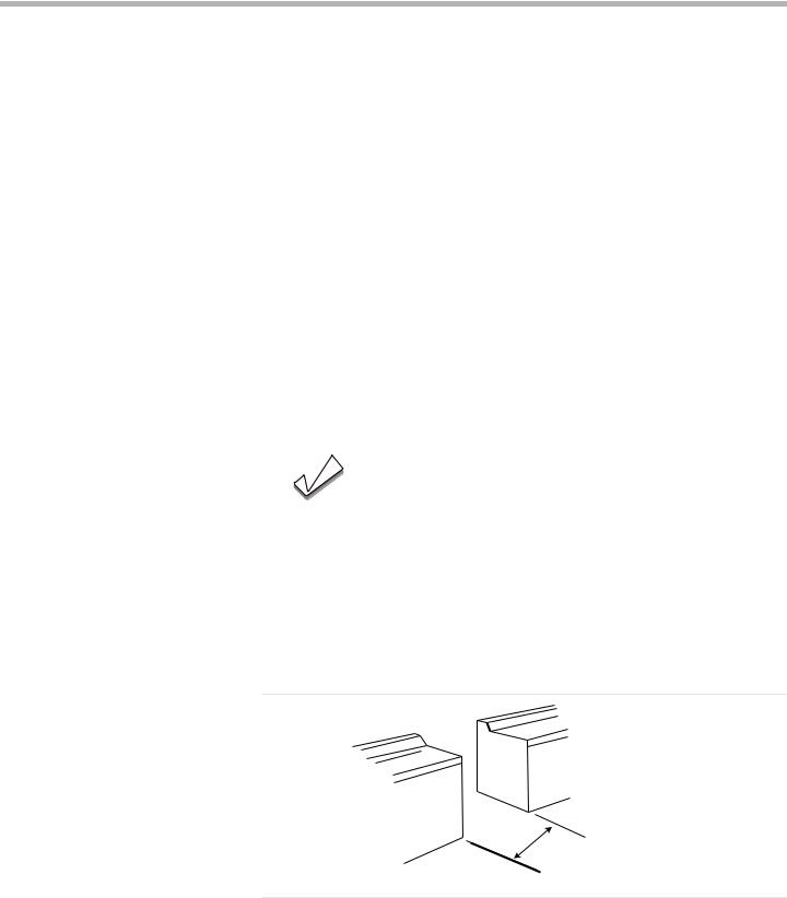
This unit is designed for installation near adjacent walls and projecting surfaces constructed of combustible materials. Allow a minimum of 30 inches (76.2 cm) between cabinets where range is to be installed (0.47” (12 mm) clearance from range sidewall to cabinet required in Canada).
30” (76.2 cm) Minimum between cabinets
Figure 1: Cabinet Clearances
These clearance instructions were determined using Standard American cabinets. Standard base cabinets measure 36 inch (91.4 cm) high x 24 inch (60.9 cm) deep. Cabinets over the cooking surface and cabinets adjacent to those over the cook-
English 3
Installation
ing surface measure 13 inches (33 cm) deep from backwall. If nonstandard cabinets are used, care should be taken to alter dimensions accordingly.
Note:
Some cabinet finishes cannot survive the temperatures allowed by U.L.for appliances, particularly self-cleaning ovens; the cabinets may discolor or stain. This is most noticeable with laminated cabinets.
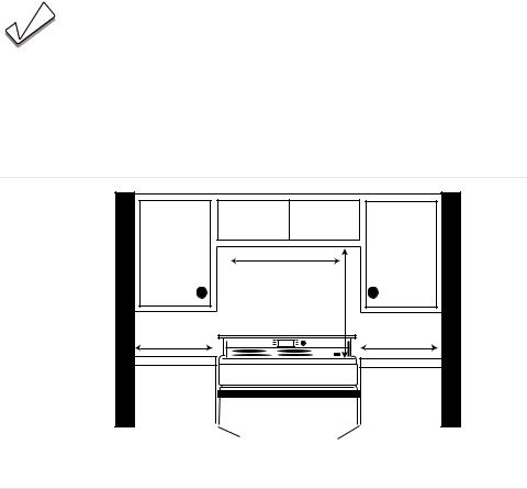
From cooktop to materials above:
There must be a minimum clearance of 30 inches (76.2 cm) between the top of the cooking surface and the bottom of an unprotected wood or metal cabinet.
|
30in (76.2 cm) |
|
|
min. centered |
|
4in (10.2 cm) |
30in (76.2 cm) min. |
4in (10.2 cm) |
min |
|
min |
no clearance required (12 mm clearance from range sidewall to cabinet required in Canada.)
Figure 2: Cooktop Clearances
24 inches (61 cm) is acceptable when the bottom of the wood or metal cabinet is protected by:
(a)not less than 1/4 inch (6.35 mm) of flame retardant material which must be covered with
(b)not less than No. 28 MSG sheet metal, 0.015 inch (.381 mm) stainless steel’ or 0.024 inch (.601 mm) aluminum or copper.
From range walls to adjacent materials, see Figure 2: Cooktop Clearances:
No clearance is required from unit walls to adjacent vertical combustible walls on rear, right or left. Clearance from range top to adjacent vertical walls must be at least 4” (10.2 cm).
English 4
Installation
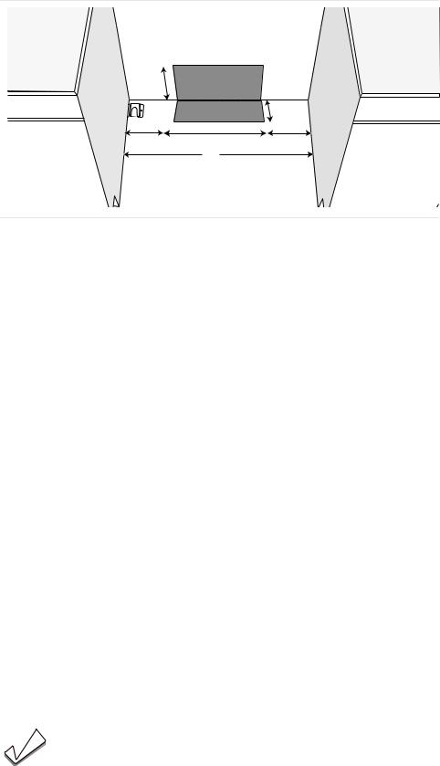
Electrical Requirements The electrical outlet must be located in the shaded space in Figure 3: Electrical Outlet Placement.
General Information
7 1/2”
(190.5 mm)
|
|
3 1/2” |
|
|
(88.9 mm) |
4 1/2” |
21” (533.4 mm) |
4 1/2” |
(114.3 mm) |
30” |
(114.3 mm) |
|
|
|
|
(762 mm) |
|
Figure 3: Electrical Outlet Placement
Verify that wiring to house is adequate.
Contact your local utility company to verify that the present electric service to your home is adequate. In some instances, the size of the wiring to the house and service switch must be increased to handle the electrical load demanded by the range.
Verify that wiring inside house is adequate.
Most wiring codes require a separate circuit with separate disconnect switch and fuses either in the main entrance panel or in a separate switch and fuse box. Most local building regulations and codes require that electrical wiring be done by licensed electricians. Be sure to install your range according to the electric codes in place in your region.
Ranges are dual rated for use on either 120/240 VAC or 120/208 VAC. See Table 1, “Electrical Specifications,” on page 6 for power ratings and circuit breaker sizes based upon the supply voltage for each model.
We recommend that the range be installed with a UL approved power cord set (not supplied). The electrical rating of the power cord set must be 120/240 volt, 50 amperes minimum. The power cord set shall be marked “For Use with Ranges.” Always use a new power cord. Alternatively, the range can also be hard wired using the terminal lugs included in the literature pack. If using this connection, flexible conduit must also be used (not supplied).
We recommend a 50 AMP, 60 Hz, 4 wire circuit; However, the NEC (National Electric Code) allows for some ranges to be installed on a 40 AMP circuit. Refer to your local electric code requirements in order to determine the required amperage. Always choose a range power cord set that is rated for the circuit. In compliance with the NEC, a separate circuit is also recommended.
Note:
In Canada, the range is shipped from the factory with the range cord already installed.
English 5

|
|
|
|
|
Installation |
|
For installations other than those in Canada, install the strain relief and connect |
||||
|
the range cord (or wire conductors) as described in the following steps. |
||||
|
Table 1: Electrical Specifications |
|
|
|
|
|
Check data plate for kW rating. Reference kW rating in table to determine |
||||
|
amperage requirements. |
|
|
|
|
|
|
|
|
|
|
|
kW Rating |
AMPS Required |
|||
|
|
|
|
|
|
|
At 120/240 Volts: |
At 120/208 Volts: |
US Models: |
|
Canadian Models: |
|
|
|
|
|
|
|
12.3 |
9.2 |
40 or 50* |
||
|
|
|
|
|
|
|
12.6 |
9.5 |
40 or 50* |
|
50 |
|
|
|
|
|
|
|
13.5 |
10.2 |
|
50 |
|
|
|
|
|
|
|
|
|
* Varies by location. Refer to local electric code. |
|||
Installation Procedure |
|
|
|
|
|
Installation Tips |
• Tape warming drawer or storage drawer shut to keep it from opening while |
||||
|
installing the range. |
|
|
|
|
•During installation, place a portion of the box or a piece of cloth under the range to protect floors.
•To make range lighter and easier to handle, remove door (see instructions in Use and Care manual).
Install Ventilation |
We strongly recommend the installation of a ventilation hood above this range. |
|
For most kitchens a certified hood rating of not less than 300 CFM is recom- |
|
mended. The range hood must be installed according to instructions furnished |
|
with the hood. |
Prepare Walls and Floor |
Seal any holes in the walls or floor. Remove any obstructions (extra electrical or |
|
gas connections, etc.) so that range will rest against wall properly. |
Prepare Range |
Place range in front of cabinets where it is to be installed. Remove any packaging. |
Install Strain Relief |
WARNING: |
|
The strain relief provided with your range cord must be properly |
|
installed. |
|
Place strain relief in knockout below terminal block. See Figure 4: Electrical Con- |
|
nection and Strain Relief Knockout Panel Locations. Feed range cord through |
|
hole and strain relief up to terminal block. Allow for slack in the cord between the |
|
strain relief and terminal block. Once cord length/ slack has been adjusted, attach |
|
strain relief per instructions included with strain relief. |
|
Tip: |
|
The knockout panel (below the terminal block) can be removed from |
|
the range to install the strain relief: Remove panel from range, install |
|
strain relief in panel and reattach. DO NOT remove entire range back |
|
panel. |
English 6
Installation
Electrical connection (found behind terminal block cover)
Feed range cord through strain relief in knockout panel here.
Connect Electric
Figure 4: Electrical Connection and Strain Relief Knockout Panel Locations
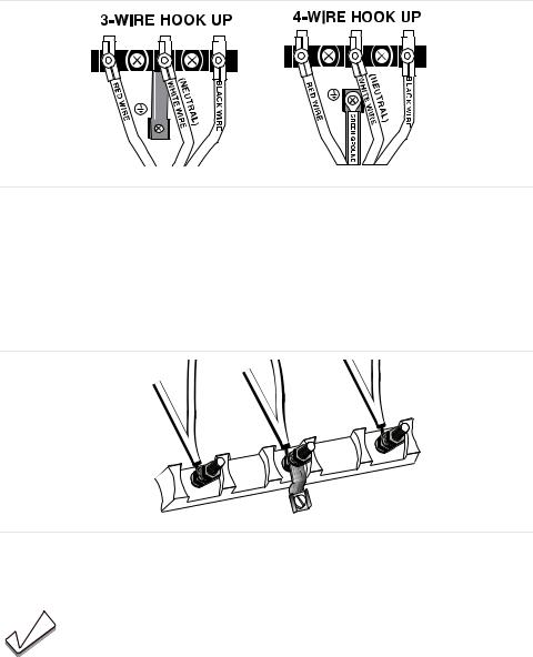
There are four possible electrical connections:
1.Four (4) wire range cord
2.Three (3) wire range cord
3.Four (4) wire flexible conduit connection (hard wire)
4.Three (3) wire flexible conduit connection (hard wire)
The four wire range cord connection is the recommended method, but where local codes permit, three wire connections are also acceptable.
As an alternative to the range cord, the appliance can also be hard wired with either a three or four wire connection. In this case, the terminal lugs supplied must be used.
Always verify that your chosen connection complies with all applicable codes. Table 1, “Electrical Specifications,” on page 6.
WARNING:
To prevent electrical shock, the grounding prong on the range cord should not be cut or removed under any circumstances. It must be plugged into a matching grounding type receptacle and connected to a correctly polarized 240Volt circuit. If there is any doubt as to whether the wall receptacle is properly grounded, have it checked by a qualified electrician.
WARNING:
Risk of Electric Shock or Fire. Frame grounded to neutral through a ground strap. Grounding through the neutral conductor is prohibited for new branch-circuit installations (1996 NEC), mobile homes, and recreational vehicles, or in an area where local codes prohibit grounding through the neutral conductor.
For installations where grounding through the neutral conductor is prohibited, (a) disconnect the link from the neutral, (b) use grounding terminal or lead to ground unit, (c) connect neutral terminal to lead branch circuit neutral in usual manner
English 7
Installation
(when the appliance is to be connected by means of a cord kit, use 4-conductor cord for this purpose)
Four Wire Range Cord Connection
(Recommended Method)
Figure 5: Grounding Options
Use only cord kits rated 125/250 volts (minimum), 50 amperes and labeled “For Use with Ranges”. Strain relief provided with cord must be installed per instructions included with cord.
1.Disconnect electrical power at breaker box.
2.Remove the terminal block cover to expose the terminal block
Figure 3: Four Wire Connection
4. Remove TOP nut, star washer, and round washer from each post.
Note:
DO NOT remove last round washer, last nut or internal wiring leads.
5. Remove screw from bottom end of ground strap.
English 8
Installation
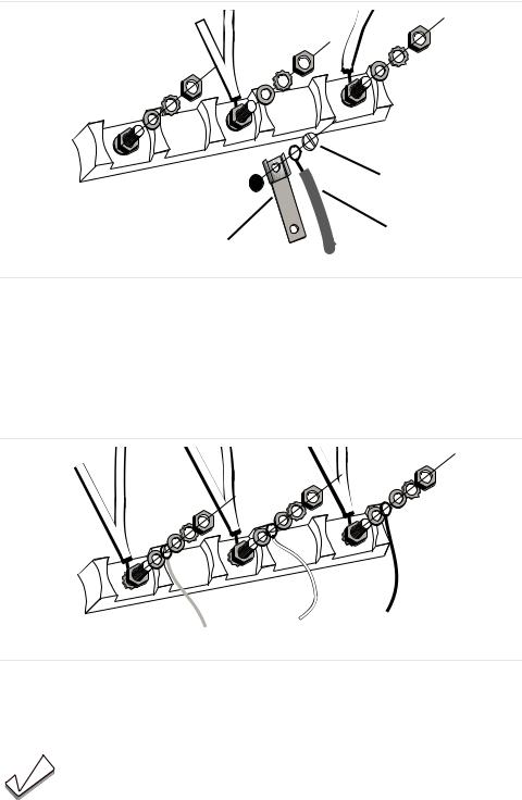
6.Remove ground strap from CENTER post, rotate so that wide end is at TOP and attach wide end to range through hole below junction box. Attach GREEN wire on TOP of ground strap. Tighten Screw.
green ground screw
ground wire
ground strap
Figure 7: Four Wire Range Cord Connection - Ground Strap and Wire
8.Attach RED wire, round washer, star washer and nut IN THIS ORDER to LEFT post.
9.Attach WHITE wire, round washer, star washer and nut IN THIS ORDER to CENTER post.
10.Attach BLACK wire, round washer, star washer and nut IN THIS ORDER to RIGHT post.
black
white
red
Figure 11: Four Wire Range Cord Connection (continued)
12.Tighten all connections securely and replace terminal block cover.
13.Properly secure strain relief. See “Install Strain Relief” on page 6.
Note:
DO NOT plug in range at this time.
Three Wire Range Cord Connection The Four Wire Connection (above) is preferred, but where local codes and ordinances permit grounding through neutral and where conversion to four wire is impractical, the unit may be connected to the power supply via a three wire connection.
1. Disconnect electrical power at breaker box.
English 9
Installation
2. Remove the terminal block cover to expose the terminal block.
Figure 3: Terminal Block
4. Remove TOP nut, star washer, and round washer from each post.
Note:
DO NOT remove last round washer, last nut or internal wiring leads.
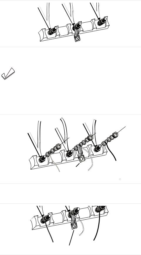
5.Attach WHITE wire, round washer, star washer and nut IN THIS ORDER on TOP of ground strap on CENTER post.
6.Attach RED wire, round washer, star washer and nut IN THIS ORDER to LEFT post.
7.Attach BLACK wire, round washer, star washer and nut IN THIS ORDER to RIGHT post.
black
ground strap
white
red
Figure 8: Three Wire Connection
9. Tighten all connections securely and replace terminal block cover.
green ground screw
Figure 10: Completed Three Wire Range Cord Connection
11. Properly secure strain relief. See “Install Strain Relief” on page 6.
English 10
Installation
Note:
DO NOT plug in range at this time.
Four Wire Flexible Conduit Connection
1.Disconnect electrical power at the breaker box.
2.Remove the terminal block cover to expose the terminal block.
3.Remove the TOP nut, star washer, and round washer from each post.
Note:
DO NOT remove last round washer, last nut or internal wire leads.
4.Remove screw from bottom end of ground strap.
5.Remove ground strap from CENTER post. Discard ground strap.
6.Attach one terminal lug (included) through hole below terminal block using ground screw.
7.Place one terminal lug (included) on each post. Replace the star washer and round washer and secure with 20 inch pounds of torque.
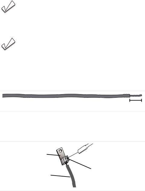
8.Strip 3/8 inches (9.53 mm) of insulation from the end of each wire.
3/8 “
Figure 9: Wire Stripping
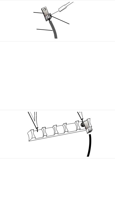
10.Insert the insulated grounding wire into the lug below the terminal block.
11.Insert stripped end of WHITE wire into the CENTER lug. Secure the clamping screw.
lug
clamping screw
wire
Figure 12: Attaching Wire to Terminal Lug
13.Insert stripped end of RED wire into the LEFT lug. Secure clamping screw.
14.Insert BLACK wire into the RIGHT lug. Secure clamping screw.
15.Tighten each clamping screw with the appropriate torque. See Table 2.
Table 2: Appropriate Torque Levels for Aluminum or Copper Wire
Gauge |
Torque (in./lbs.) |
Torque (Nm) |
|
|
|
6 |
35 |
3.95 |
|
|
|
8 |
25 |
2.82 |
|
|
|
English 11
Installation
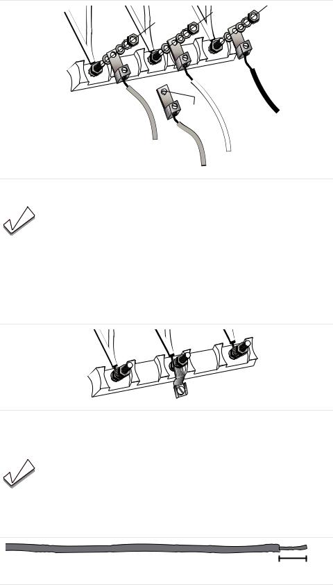
16.Properly secure flexible conduit at knockout on angle and at supply side junction box. The wiring is now complete.
Three Wire Flexible Conduit Connection
green
ground black wire screw
red wire
white wire
green ground wire
Figure 17: Completed Four Wire Flexible Conduit Connection
Note:
DO NOT plug in range at this time.
The Four Wire Connection is preferred, but where local codes and ordinances permit grounding through neutral and/or conversion to four wire is impractical, unit may be connected to the power supply via a three wire connection.
1.Disconnect electrical power at the breaker box.
2.Remove the terminal block cover to expose the terminal block.
Figure 3: Terminal Block
4. Remove the TOP nut, star washer, and round washer from each post.
Note:
DO NOT remove last round washer, last nut or internal wire leads.
5.Place one terminal lug (packaged with this manual) on each post. Replace the star washer and round washer and secure with 20 inch pounds of torque.
6.Strip 3/8 (9.53 mm) inches of insulation from the end of each wire.
3/8 “
Figure 7: Wire Stripping
English 12
Installation
8.Insert stripped end of WHITE wire into the CENTER lug on TOP of the ground strap. Secure the clamping screw.
lug
clamping screw
wire
Figure 9: Attaching Wire to Terminal Lug
10.Insert stripped end of RED wire into the LEFT lug. Secure clamping screw.
11.Insert stripped end of BLACK wire into the RIGHT lug. Secure clamping screw.
12.Tighten each clamping screw with the appropriate torque. See Table 3.
Table 3: Appropriate Torque Levels for Aluminum or Copper Wire
Gauge |
Torque (in./lbs.) |
Torque (Nm) |
|
|
|
6 |
35 |
3.95 |
|
|
|
8 |
25 |
2.82 |
|
|
|
13.Properly secure flexible conduit at knockout panel on range and at supply side junction box. The wiring is now complete.
green ground screw
Figure 14: Completed Three Wire Flexible Conduit Connection
Note:
DO NOT plug in range at this time.
Anti-tip Bracket
Attach anti-tip bracket to floor |
WARNING |
RANGE TIPPING HAZARD
All ranges can tip and injury could result. To prevent accidental tipping of the range, attach it to the floor by installing the Anti-Tip Device supplied.
English 13
Loading...