


FC700A
Fire detection system
Planning
Fire & Security Products
Siemens Building Technologies
Liefermöglichkeiten und technische Änderungen vorbehalten.
Data and design subject to change without notice. / Supply subject to availability. Sous réserve de modifications techniques et de la disponibilité.
© 2004 Copyright by
Siemens Building Technologies AG
Wir behalten uns alle Rechte an diesem Dokument und an dem in ihm dargestellten Gegenstand vor. Der Empfänger anerkennt diese Rechte und wird dieses Dokument nicht ohne unsere vorgängige schriftliche Ermächtigung ganz oder teilweise Dritten zugänglich machen oder außerhalb des Zweckes verwenden, zu dem es ihm übergeben worden ist.
We reserve all rights in this document and in the subject thereof. By acceptance of the document the recipient acknowledges these rights and undertakes not to publish the document nor the subject thereof in full or in part, nor to make them available to any third party without our prior express written authorization, nor to use it for any purpose other than for which it was delivered to him.
Nous nous réservons tous les droits sur ce document, ainsi que sur l'objet y figurant. La partie recevant ce document reconnaît ces droits et elle s'engage à ne pas le rendre accessible à des tiers, même partiellement, sans notre autorisation écrite préalable et à ne pas l'employer à des fins autres que celles pour lesquelles il lui a été remis.

1 |
About this document .............................................................................. |
6 |
2 |
Safety regulations................................................................................... |
8 |
2.1 |
Signal words and symbols ........................................................................ |
8 |
2.1.1 |
Signal words and their meaning................................................................ |
8 |
2.1.2 |
Symbols and their meaning ...................................................................... |
8 |
2.1.3 |
Classification and meaning of additional symbols .................................... |
9 |
2.2 |
Safety-relevant working instructions ......................................................... |
9 |
3 |
Main features......................................................................................... |
11 |
4 |
Technical data FC700A......................................................................... |
12 |
5 |
Logical and physical structure............................................................ |
13 |
6 |
Bus systems.......................................................................................... |
14 |
6.1 |
Bus overview........................................................................................... |
15 |
6.2 |
Modifying the impedance of the various C-Bus cables........................... |
15 |
6.2.1 |
Diagram................................................................................................... |
16 |
7 |
C-Bus stations....................................................................................... |
17 |
7.1 |
Station ..................................................................................................... |
17 |
7.2 |
Types of stations..................................................................................... |
17 |
7.3 |
Hardware................................................................................................. |
17 |
7.4 |
Visualizer for Windows remote operation software (not available yet) ... |
18 |
7.5 |
Logical AREAS........................................................................................ |
19 |
8 |
Limitations of C-Bus participants ....................................................... |
20 |
8.1 |
Main CPU limits....................................................................................... |
20 |
8.1.1 |
Maximum number of devices .................................................................. |
20 |
8.1.2 |
Limits in the logical structure................................................................... |
20 |
8.1.3 |
Maximum number of criteria in zones control 4 and 6............................ |
20 |
8.1.4 |
Maximum number of ZONE time channel............................................... |
20 |
8.1.5 |
Maximum number of I-Bus-modules....................................................... |
21 |
8.1.6 |
Limits of 5V supply.................................................................................. |
21 |
8.2 |
Control terminal limits (FC/FT)................................................................ |
21 |
8.2.1 |
Limitation of visible texts on a FC700A................................................... |
21 |
8.2.2 |
Limitation of visible texts on a FT700A ................................................... |
21 |
8.3 |
Gateway limits (FG) ................................................................................ |
22 |
9 |
Specify hardware required................................................................... |
23 |
10 |
Control unit FC700A ............................................................................. |
24 |
10.1 |
Configuration........................................................................................... |
24 |
10.2 |
Block diagram ......................................................................................... |
25 |
10.3 |
Modules................................................................................................... |
25 |
11 |
Auxiliary power supply......................................................................... |
26 |
11.1 |
Configuration........................................................................................... |
26 |
11.2 |
Block diagram ......................................................................................... |
26 |
11.3 |
Modules................................................................................................... |
26 |
12 |
Control terminal B3Q700 (FC/FT) ........................................................ |
27 |
12.1 |
Features .................................................................................................. |
27 |
12.2 |
Options.................................................................................................... |
27 |
12.2.1 |
Plexiglas door to B3Q700 (FC/FT).......................................................... |
27 |
12.2.2 |
Place of the E3I020 RS232 module (FT)................................................ |
28 |
12.2.3 |
Place of the E3I040 LON interface (FT) ................................................. |
28 |
|
|
3 |
Siemens Building Technologies |
007836_a_en_--.doc |
|
Fire & Security Products |
03.2004 |
|

12.3 |
Installation possibilities (FT).................................................................... |
29 |
12.4 |
Block diagram ......................................................................................... |
29 |
12.5 |
Connection lines between control unit and external operating units ...... |
30 |
12.6 |
Power supply (24V)................................................................................. |
30 |
12.7 |
Modules................................................................................................... |
31 |
13 |
Range of cabinets H23 / H26 / H28 ...................................................... |
32 |
13.1 |
Recessed mounting H23G230 and H28G200 ........................................ |
33 |
13.2 |
Modules................................................................................................... |
33 |
14 |
19” accessories..................................................................................... |
34 |
14.1 |
Modules................................................................................................... |
34 |
15 |
Line modules ......................................................................................... |
35 |
15.1 |
Overview ................................................................................................. |
35 |
15.2 |
Modules................................................................................................... |
35 |
15.3 |
Detection line "addressable" SynoLOOP................................................ |
36 |
15.4 |
Detection line "collective" SynoLINE600/-Ex .......................................... |
37 |
16 |
Connection factors, line resistances and capacitances ................... |
38 |
16.1 |
Terminology and abbreviations............................................................... |
38 |
16.2 |
Collective detection line .......................................................................... |
38 |
16.3 |
Addressable detection line...................................................................... |
38 |
16.4 |
Line resistance and capacitance............................................................. |
39 |
17 |
Control modules.................................................................................... |
40 |
17.1 |
Application of control modules ................................................................ |
40 |
17.1.1 |
Overview of the available modules with control outputs ......................... |
40 |
17.2 |
Means of linking ...................................................................................... |
40 |
17.3 |
Control outputs station type FC700A ...................................................... |
41 |
17.4 |
Control outputs remote station type FT700A .......................................... |
41 |
17.5 |
Modules................................................................................................... |
41 |
17.6 |
CPU-overlapping controls ....................................................................... |
42 |
17.7 |
Mimic Display panel outputs ................................................................... |
43 |
17.8 |
Modules................................................................................................... |
43 |
17.9 |
Relay outputs .......................................................................................... |
44 |
17.10 |
Modules................................................................................................... |
44 |
18 |
LON-Bus devices .................................................................................. |
45 |
18.1 |
Features .................................................................................................. |
45 |
18.2 |
LON-Bus as stub line .............................................................................. |
45 |
18.3 |
LON-Bus as free topology....................................................................... |
46 |
18.4 |
LON/Mimic Display p.c.b K3I050 ............................................................ |
46 |
18.5 |
LON I/O card K3I110............................................................................... |
46 |
18.6 |
Indicator devices B3Q580 and B3Q590/595........................................... |
47 |
18.7 |
Modules................................................................................................... |
47 |
19 |
Gateway.................................................................................................. |
48 |
19.1 |
Main features .......................................................................................... |
48 |
19.2 |
Application............................................................................................... |
48 |
19.3 |
Modules................................................................................................... |
49 |
20 |
Remote transmission............................................................................ |
50 |
21 |
Printer interface..................................................................................... |
51 |
4
Siemens Building Technologies |
007836_a_en_--.doc |
Fire & Security Products |
03.2004 |
21.1 |
Features .................................................................................................. |
51 |
21.2 |
Application variant FT ............................................................................. |
51 |
21.3 |
Application variant FC............................................................................. |
51 |
21.4 |
Modules................................................................................................... |
51 |
22 |
Power supply......................................................................................... |
52 |
22.1 |
Concept................................................................................................... |
52 |
22.2 |
Special functions..................................................................................... |
52 |
22.3 |
Application............................................................................................... |
52 |
22.4 |
Power supply for the control unit............................................................. |
52 |
22.5 |
Auxiliary power supply ............................................................................ |
52 |
22.6 |
Modules................................................................................................... |
53 |
22.7 |
Operation with power supply from control unit........................................ |
53 |
22.8 |
Power supply for remote transmission equipment and accessories....... |
53 |
23 |
Emergency power supply .................................................................... |
54 |
23.1 |
Specifying battery capacity ..................................................................... |
54 |
23.1.1 |
Battery rated capacity ............................................................................. |
54 |
23.1.2 |
Ageing of battery..................................................................................... |
54 |
23.1.3 |
Calculation .............................................................................................. |
54 |
23.2 |
Capacity values for standard configurations........................................... |
54 |
23.3 |
Quiescent current table........................................................................... |
55 |
24 |
Alarm concept ....................................................................................... |
56 |
24.1 |
Cerberus Alarm Concept (CAC) ............................................................. |
56 |
24.2 |
Principle of the Cerberus alarm concept................................................. |
56 |
24.3 |
Determine the alarm organization........................................................... |
57 |
24.4 |
Organization of system operation ........................................................... |
57 |
25 |
Commissioning ..................................................................................... |
58 |
26 |
Parameterization, Flash programming ............................................... |
59 |
26.1 |
Functions................................................................................................. |
59 |
26.2 |
Modules................................................................................................... |
59 |
27 |
FC700A modules in alphabetical order .............................................. |
60 |
28 |
Spare parts ............................................................................................ |
62 |
29 |
Configuration sheets ............................................................................ |
63 |
29.1 |
List of configuration sheets ..................................................................... |
63 |
30 |
Control unit FC700A ............................................................................. |
64 |
31 |
Auxiliary power supply......................................................................... |
65 |
32 |
Control terminal FT700A ...................................................................... |
66 |
33 |
Display & operating terminals ............................................................. |
67 |
34 |
Externally placed modules................................................................... |
68 |
|
5 |
|
|
Siemens Building Technologies |
007836_a_en_--.doc |
Fire & Security Products |
03.2004 |

About this document
1 |
About this document |
|
|
|
|
|
|
|
|
|
|
|
|
Purpose |
|
|
|
|
|
This document describes the project planning of the hardware modules of the con- |
|
||
|
|
trol unit FC700A. The consistent adherence to these instructions is a prerequisite |
|
||
|
|
for a safe application. |
|
|
|
|
|
Scope |
|
|
|
|
|
This document contains information of all FC700A components, including part |
|
||
|
|
numbers for ordering. |
|
|
|
|
|
Target group |
|
|
|
|
|
This product documentation and the work instructions are aimed at the following |
|
||
|
|
persons, who have a particular function and have the corresponding training and |
|
||
|
|
qualification. |
|
|
|
|
|
|
|
|
|
Group of persons |
Activity |
|
Qualification |
|
|
Project Manager |
The project manager is responsible for the local |
He has had the technical training appropriate to |
|
||
|
|
project management. He co-ordinates the sched- |
his function and the size of a project or the prod- |
|
|
|
|
ules of all groups of people working on a project |
uct line used in the project and has attended the |
|
|
|
|
as well as resources. He also continuously ob- |
training courses for project managers at the sup- |
|
|
|
|
tains the technical information required for project |
plier’s works. |
|
|
|
|
realization. |
|
|
|
|
|
Reference documents |
|
|
|
|
|
Information in |
Document |
|
|
|
|
007831 |
Hardware description |
|
|
|
|
007827 |
Installation housing H26... /H28... |
|
|
|
|
007832 |
Visualizer Customizing / End user (not yet available) |
|
|
|
|
007835 |
Operating instructions |
|
|
|
|
007828 |
Installation / Hardware Commissioning |
|
|
|
|
007833 |
Maintenance instructions |
|
|
|
|
007894 |
Templates for inscription stripes |
|
|
|
|
007895 |
Operating platform for Tools |
|
|
Work and operational safety
Before personnel begin work on the system they must have read and understood the related operating instructions, in particular chapter 2 ”Safety regulations”.
Disregard of the safety regulations
Before they are delivered, products are tested to ensure they function correctly when used properly. Siemens disclaims all liability for damage or injuries caused by the incorrect application of the instructions or disregard of warnings of danger contained in the documentation. This applies in particular to:
–Personal injuries or damage caused by improper use and incorrect use;
–Personal injuries or damage caused by disregarding safety instructions in the documentation or on the product;
–Personal injuries or damage caused by poor maintenance or a lack of maintenance.
6
Siemens Building Technologies |
007836_a_en_--.doc |
Fire & Security Products |
03.2004 |
|
|
About this document |
Conventions |
|
|
(...) |
|
Additional information |
..) |
|
Notes |
’’......’’ / ’.....’ |
|
Definitions of designations |
-> |
|
Details see page ...., chapter or document ..... |
|
|
Configuration sheets to fill out |
Document identification |
|
|
Place |
|
Signification |
Title page |
|
– System names |
|
|
– Product type |
|
|
– Document purpose |
Last page |
bottom left |
– The document number consists of: Language, number, index |
|
|
– Version date |
|
bottom right |
– Manual |
|
|
– Register |
Modification index
Version |
Date |
Brief description |
007836_a_en_-- |
03. 2004 |
First edition |
|
7 |
|
|
Siemens Building Technologies |
007836_a_en_--.doc |
Fire & Security Products |
03.2004 |
Safety regulations
2 Safety regulations
This chapter describes the danger levels and the relevant safety regulations applicable for the use of our products. Please read the work instructions as well as the chapter ”About this document” thoroughly before beginning any work.
2.1Signal words and symbols
2.1.1Signal words and their meaning
The danger level that is, the severity and probability of danger are indicated by the signal words listed below. Non-observance may lead to the consequences indicated:
DANGER
Imminent danger!
May cause serious bodily injury or danger to life!
WARNING
Dangerous situation!
May cause serious bodily injury or danger to life!
CAUTION
Possibly dangerous situation!
May cause light injuries!
NOTE
Possibly harmful situation!
May cause damage to the product or to objects in the immediate vicinity of the product!
2.1.2Symbols and their meaning
The symbols listed below indicate the nature and origin of the danger.
Signal word |
General danger |
|
|
|
|
Signal word |
Electrical voltage |
|
|
Example for a danger warning
DANGER |
Disconnect the module from power supply. |
|
External voltage |
||
|
||
|
|
8
Siemens Building Technologies |
007836_a_en_--.doc |
Fire & Security Products |
03.2004 |
Safety regulations
2.1.3Classification and meaning of additional symbols
Tips and information
Refers to extremely important or critical decisions to be taken into account before continuing the work.
2.2Safety-relevant working instructions
Country-specific standards
The products are developed and produced in compliance with the relevant international and European safety standards. Should additional country-specific, local safety standards or regulations concerning project planning, assembly, installation, operation and disposal of the product apply in the place of operation, then these standards or regulations must also be taken into account in addition to the safety regulations mentioned in the product documentation.
Electrical installations
DANGER |
Any work on electrical installations may only be carried out by qualified electri- |
Work on electrical |
cians or instructed persons working under the guidance and supervision of a |
installations |
qualified electrician, in accordance with the electro technical regulations. |
Control units must be disconnected from the power supply during commissioning or maintenance work.
Terminals with an external voltage supply must be provided with a sign ”DANGER - External voltage”.
Mains leads to the control unit must be installed separately and provided with a clearly marked fuse.
Earthing must be carried out in compliance with local safety regulations. When work is carried out in explosion-hazardous areas, the appropriate safety precautions must be taken.
Assembly, installation, commissioning and inspection work
If any tools or accessories such as ladders are required, safe and suitable devices must be used.
Prevention of spurious tripping of the remote transmission must be assured. Always inform the fire brigade before testing the remote transmission.
The activation of fire control installations for test purposes must not cause damage to the system or parts thereof.
Fire control installations must only be activated after the test has been completed and the system has been handed over to the customer.
Third party systems or devices must only be activated in the presence of the responsible person.
When work on management stations and system terminals are performed, the safety regulations of the connected sub-systems must be observed. This especially applies when switching-off system components.
In the case of extinguishing systems, always use the ”General installation instructions” as a guideline. This guideline is available on request.
|
9 |
|
|
Siemens Building Technologies |
007836_a_en_--.doc |
Fire & Security Products |
03.2004 |

Safety regulations
Testing the product operability
Evacuate and cordon off extinguishing sector.
Inform people about the possibility of occurring fog and noise.
Inform people before testing of alarm devices; take the possibility of panic reactions into account.
Inform the alarm and fault receiving stations connected to the system before running the tests.
Modifications to the system design and the product
Modifications to a system or to individual products may cause faults or malfunctioning. Please request written approval from us, and the relevant authorities concerning intended system modifications and system extensions.
Modules and spare parts
Locally procured modules and spare parts must comply with the technical specifications laid down by the manufacturer. This compliance is always ensured for original spare parts supplied by us.
Only use fuses with the specific fuse characteristics.
Wrong battery types and improper battery exchange may introduce the danger of explosion. Only use the specified battery type or an equivalent battery type recommended by the manufacturer.
Batteries require environmentally safe disposal. They must be handed in at the local collecting points.
Please take into account that the extinguishing agent cylinders are pressurized and must be exchanged in compliance with the local safety regulations.
10
Siemens Building Technologies |
007836_a_en_--.doc |
Fire & Security Products |
03.2004 |
Main features
3 Main features
Fire detection system for modular configuration
Up to 1000 detectors per FC700A possible
For the processing of addressable and conventional detectors
Logical and physical structure totally separated
Control console as main CPU
Interfaces for VdS peripheral equipment, printer, host systems
Different types of input and output modules
Special Mimic Display terminal activating module
Multidetector logic
Up to 16 free selectable type of stations per C-Bus
Comfortable operation with soft keys and large LC display
Up to 64 independent logical AREAS (Organization levels)
Single-AREA or multi-AREA operation
Event memory with sub-menu / search functions
Integrated real time clock with auxiliary battery
Automatic summer/winter time switchover
Integrated emergency operation function
Flexible detector parameters setting via maintenance PC
Connectible detector systems |
|
Stations |
|
|||
Synova™ 300/600, Special detectors |
|
|||||
|
|
|||||
|
|
|
|
|
Control terminal / Main-CPU ‘FC700A’ |
Control terminal ‘FT700A’ |
|
|
|
|
|
B3Q700 |
B3Q700 |
SynoLOOP |
|
|
|
|
|
|
|
|
|
|
|
CPU |
|
|
|
|
|
|
WINDOWS based |
FG700A |
SynoLINE300 |
|
|
|
|
Configuration software |
|
|
|
|
|
|
|
|
|
|
DO1101A-Ex |
EEx ib |
IIC T4 |
Gateway |
|
ype |
S |
PTB Nr. |
||||
T |
|
|
EN |
|
|
|
s® |
|
M |
|
|
||
E |
|
|
|
|||
ru I |
|
|
|
|
||
be S |
|
|
|
|
|
|
r |
|
|
|
|
|
|
e |
|
|
|
|
|
|
C |
|
|
|
|
|
|
SynoLINE600 / SynoLINE600-Ex |
|
|
|
|||
|
|
|
|
|
SWE700A |
|
Special detectors |
|
|
|
|
|
|
|
11 |
|
|
Siemens Building Technologies |
007836_a_en_--.doc |
Fire & Security Products |
03.2004 |

Technical data FC700A
4 |
Technical data FC700A |
|
|
|
|
|
|
Operating voltage |
|
115 / 230VAC |
±15% |
50... 60Hz |
|||
Power consumption |
|
40... 220VA (per converter B2F020) |
|
||||
Battery operation in the event of mains failure |
|
|
|
|
|
||
- |
Standard operating period |
|
12...24h |
|
|
|
|
- |
Optional |
|
Up to 72h (see chapter 23) |
|
|
||
Environmental conditions |
|
|
|
|
|
|
|
Temperature during |
operation |
0°C... +40°C |
|
|
|
||
|
|
Storage |
-20°C... +60°C |
|
|
|
|
Humidity |
|
Max. 95%, no condensation |
|
|
|||
|
|
|
Complies with class 3K5 according to IEC 721–3–3 |
||||
IP protection category (EN 60529 / IEC 529) |
|
|
|
|
|
|
|
- |
Control unit |
|
IP50 |
|
|
|
|
- |
Remote control terminal |
|
IP52 |
H26G220 cabinet |
|
|
|
|
|
|
IP40 |
H28G200 cabinet |
|
|
|
Dimensions |
|
|
|
|
|
|
|
- |
Control unit cabinet |
|
W = |
520mm, |
H = 602mm, |
D = 100mm / 155mm |
|
- |
Separate control terminal |
in cabinet H26G220 |
W = |
366mm, |
H = 219mm, |
D = 76mm |
|
|
|
H28G200 |
W = 520mm, |
H = 300mm, |
D = 70mm |
||
Colors |
|
|
|
|
|
|
|
- |
Control unit cabinet |
|
RAL 7035 light grey |
|
|
||
- Operating unit front terminal B3Q700 |
|
Dark grey like Pantone 431C, Pantone 429C grey |
|||||
- |
Control terminal cabinet |
H26G220 |
Pantone 421 grey |
|
|
|
|
|
|
H28G200 |
RAL 7035 light grey |
|
|
||
|
|
H28T110/120 |
1E110 dark grey |
|
|
|
|
12
Siemens Building Technologies |
007836_a_en_--.doc |
Fire & Security Products |
03.2004 |

Logical and physical structure
5 Logical and physical structure
|
In the FC700A fire detection system, the logical structure is completely separated |
||
|
from the physical structure. This enables the greatest possible flexibility. Display |
||
|
and control terminal are based on the geographical and organizational aspects and |
||
|
are independent of the actual hardware installation of the detector network. |
|
|
|
Geographical features (-> building structure) |
|
|
|
2nd floor |
|
1st floor |
|
1st floor |
Room 101 |
|
|
Room 102 |
|
|
|
|
|
|
|
ground floor |
Room 103 |
|
|
Room 104 |
|
|
|
|
|
|
|
|
Room 104 (Zone) |
|
Main building (Area) |
1st floor (Section) |
|
|
Logical structure
The logical structure is a configuration of the geographical features of a system. It can be modified easily to the building structure, room utilization etc.
Within the same control unit the logical structure is independent of the wiring of the detector network.
Linking
The lowest levels of both structures are linked to each other. It is determined which physical devices (e.g. detectors) are in which logical or geographical location.
logical structure
Area |
|
|
|
Main |
|
|
|
|
|
|
|
building |
|
|
|
Section |
|
Ground |
|
1st |
|
2nd |
|
|
|
floor |
|
floor |
|
floor |
|
Zone |
Ware |
Reception |
Room |
Room |
Room |
Canteen |
EDP |
|
house |
|
102 |
103 |
104 |
room |
Element
Linking
Level 2
Level 1 |
|
|
Device |
|
SynoLOOP |
Level 2 |
Line 2 |
Line 3 |
Line 1 |
|
|
|
Line 4 |
|
|
|
|
Level 1 |
|
Line modules E3M111 |
|
|
|
Function unit |
|
I-Bus |
Physical structure |
C-Bus |
|
Control unit ‘FC’ |
||
The physical structure is a configuration of the |
||
hardware. It results from the hardware instal- |
Control terminal ‘FT’ |
|
Station |
||
lation. The number of used levels is depend- |
||
|
||
ing on the type of hardware. |
physical structure |
|
13 |
|
|
Siemens Building Technologies |
007836_a_en_--.doc |
Fire & Security Products |
03.2004 |
Bus systems
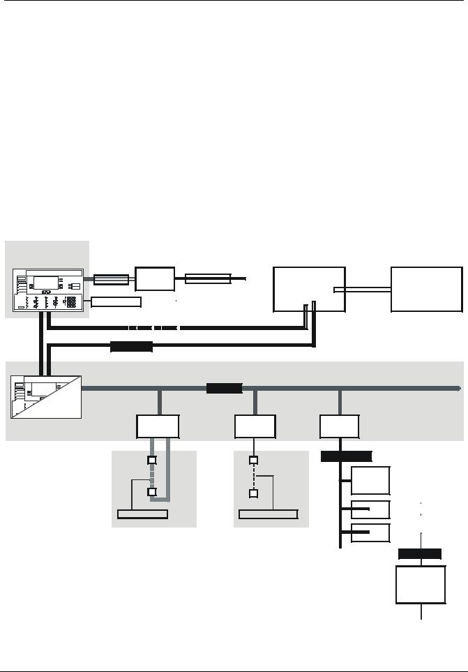
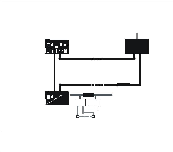
6 Bus systems
In the FC700A fire detection system there are 5 communication levels:
I-Bus
Internal data bus between individual modules in the control unit (line modules, control modules etc.)
C-Bus
Local data bus between control unit(s), control terminal(s) and Gateway(s)
SynoLOOP and SynoLINE600
Local detector bus; connects the detectors to the control unit
LON-Bus
Local data bus for floor repeater panels, mimic display converter and LON I/O card
Data Bus
Local data bus for parallel indicator panel, synoptic panel or relay
Control terminal
FT700A |
|
|
|
|
|
|
|
|
|
|
|
|
|
|
|
|
|
|
|
|
|
Gateway |
|
|
|||
|
|
|
|
|
|
|
|
|
|
|
|
|
|
|
|
|
|
|
|
|
FG700A |
|
|
|||
|
|
|
|
|
E3I040 |
|
|
|
|
|
|
|
|
|
|
|
|
Building |
||||||||
|
|
|
|
|
|
|
|
LON-Bus |
|
|
|
|
|
|
|
|
||||||||||
|
I-Bus |
|
|
|
|
|
|
|
|
|
|
|
|
|
RS232 |
|||||||||||
|
|
|
|
|
|
|
|
|
E3H020 |
|
|
management |
||||||||||||||
|
|
|
|
|
|
|
|
|
|
|
|
|
||||||||||||||
|
|
|
|
|
|
|
|
|
|
|
|
|
|
|
|
|
|
|
|
|
|
|
|
system |
||
|
|
|
|
|
|
|
|
|
|
|
|
|
|
|
|
|
|
|
|
|
|
|
|
|
|
|
|
Databus |
|
|
|
|
|
|
|
|
|
|
|
|
|
|
|
|
|
|
|
|
|
|
ISO1745 Protocol |
||
|
|
|
|
|
|
|
|
|
|
|
|
|
|
|
|
|
|
|
|
|
|
|
||||
|
|
|
|
|
|
|
|
|
|
|
|
|
|
|
|
|
|
|
|
|
|
|
|
|
|
|
|
|
|
|
|
|
|
|
|
|
|
|
|
|
|
|
|
|
|
|
|
|
|
|
|
|
|
|
|
|
|
|
|
|
|
|
|
|
|
|
|
|
|
|
|
|
|
|
|
|
|
|
|
|
C-Bus |
|
|
|
I-Bus |
Control unit FC700A |
|
|
|
CPU |
Line modules |
|
B3Q700 |
|
|
|
|
|
E3M111 |
E3M080 |
E3I040 |
|
|
LON-Bus |
|
|
B3Q580/ |
|
|
B3Q590/ |
|
|
B3Q595 |
|
|
|
|
|
|
|
|
|
|
|
|
|
|
|
|
|
|
|
|
|
|
|
|
|
|
|
K3I110 |
In-/Outputs |
|
|
|
|
|
|
|
|
|||
SynoLOOP |
|
SynoLINE600 |
|
|
|||||
|
|
|
|
|
|
||||
|
|
|
|
|
|
|
|
|
|
|
|
|
|
|
|
|
K3I050 |
|
|
|
|
|
|
|
|
|
|
|
|
|
|
|
|
|
|
|
|
|
|
|
|
|
|
|
|
|
|
|
|
Databus
B3R051 or
K3R072/
K3G060
14
Siemens Building Technologies |
007836_a_en_--.doc |
Fire & Security Products |
03.2004 |

|
|
|
|
|
|
|
Bus systems |
|
6.1 |
Bus overview |
|
|
|
|
|
||
|
|
|
|
|
|
|
|
|
Features |
|
C-Bus |
I-Bus |
SynoLOOP |
SynoLINE600 |
LON-Bus |
Data Bus |
|
Field of applica- |
|
|
|
|
Local data bus |
Local data bus |
||
tion |
|
|
|
For addressable |
For collective |
parallel ind. |
||
|
Local system bus |
Inside control unit |
for floor indicator |
|||||
|
|
detectors |
detectors |
panel, synoptic |
||||
|
|
|
|
panels |
||||
|
|
|
|
|
|
panel or relay |
||
|
|
|
|
|
|
|
||
Speed of trans- |
57kBaud |
1000kBaud |
2 messages/sec |
(Direct current |
78kBaud |
SPI-Bus 2KHz |
||
mission |
|
signal) |
||||||
|
|
|
|
|
|
|||
Length of line |
Max. 1000m |
Max. 3m (only |
|
Max. |
Max. 500m as |
|
||
|
|
Max. 150Ω/300nF |
free topology |
Max. 1000m |
||||
|
|
150/250Ω/4µF |
||||||
|
|
(G51 0,8: 1400m) |
inside cabinet) |
See chapter 16 |
Max. 1000m as |
|||
|
|
See chapter 16 |
|
|||||
|
|
|
|
|
stub line |
|
||
|
|
|
|
|
|
|
||
Number of users |
… 16 |
… 16 |
… 128 |
1 address |
… 32 |
… 24 |
||
connected or |
(Max. 25 detec- |
LON-Bus de- |
||||||
C-Bus devices |
I-Bus modules |
D-Bus devices |
Max. 8 addresses |
|||||
addresses |
|
tors) |
vices |
|||||
|
|
|
|
|
||||
Number of wires |
2 |
26 |
2 |
2 |
2 |
6 |
||
|
|
(+3 wires for emer- |
||||||
|
|
(+3 wires supply) |
||||||
|
|
gency operation) |
|
|
|
|
||
|
|
|
|
|
|
|
||
Type of cable |
Twisted 1) |
Flat cable |
Twisted |
Twisted |
Twisted |
Twisted |
||
|
|
(Un-twisted per- |
(Un-twisted |
|||||
|
|
|
|
missible) |
permissible) |
|
|
|
Loop line |
|
|
– |
|
– |
– |
– |
|
T-branch |
|
– |
– |
– |
– |
|
– |
|
|
|
(See chapter 18) |
||||||
|
|
|
|
|
|
|
||
Short-circuit proof |
Yes |
|
Yes |
|
|
|
||
|
|
Each user con- |
– |
Each user con- |
No |
No |
Yes |
|
|
|
nected with line |
nected with line |
|||||
|
|
|
|
|
|
|||
|
|
separator |
|
separator |
|
|
|
|
Network structure |
Master/master |
Master/slave |
Master/slave |
Master/slave |
Master/slave |
Master/slave |
||
Scanning |
|
Event-controlled, |
Cyclic, |
Cyclic |
|
Event-controlled, |
|
|
|
|
- typ. all 64s |
– |
presence moni- |
Cyclic |
|||
|
|
presence monitoring |
Event controlled |
- Interrupt on |
toring |
- typ. all 250ms |
||
|
|
|
||||||
|
|
|
|
alarm |
|
(All 60s) |
|
|
Principle |
|
Serial Bus |
|
Sensor/actor-Bus |
Conventional |
Network |
|
|
|
|
C-Bus |
- Cerberus proto- |
|
||||
|
|
- Echelon Chip |
Serial bus |
|||||
|
|
- Cerberus protocol |
col 'K31' |
- Current gain |
||||
|
|
- Cerberus protocol |
(LON protocol) |
- Cerberus proto- |
||||
|
|
- Collision detection |
- Serial 8bit |
principle |
||||
|
|
- Manchester coding |
- SPI/Motorola |
- Start-up: daisy- |
- Voltage levels |
- Cerberus |
col |
|
|
|
|
|
chain |
|
specific telegram |
|
|
|
|
|
|
|
|
|
||
1Calibrated according to cable impedance: 50Ω (MICC) / 110Ω (G51, ø 0.8mm, not shielded)
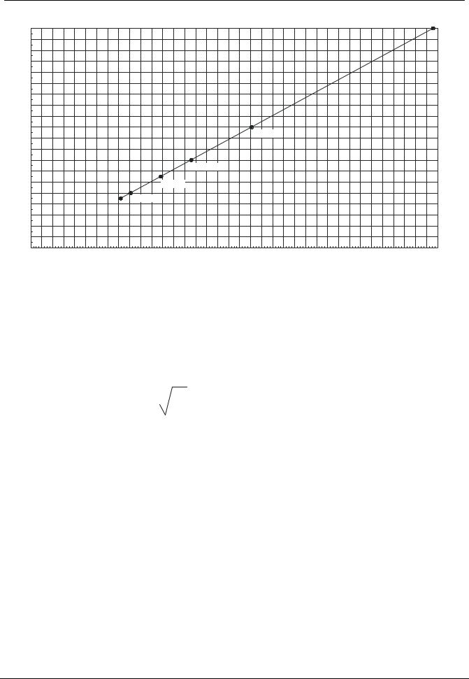
6.2Modifying the impedance of the various C-Bus cables
C-Bus standard cables have a characteristic impedance of 110Ω. The driver and end-of-line resistors are soldered to solder lugs and can be adapted accordingly with other characteristic impedances (see diagram chapter 6.2.1).
1. Explanation
A cable must be terminated with resistors. The resistance value must correspond to the impedance of the cable. Each C-Bus user has four end-of-line resistors (Ri). In addition two driver resistors (Rd) are integrated on the p.c.b. In order that the resistors can be exchanged easily they are all soldered to solder lugs.
C-Bus p.c.b. |
Ri |
Rd |
B3Q700 |
R31 ... R34 |
R49, R50 |
E3H020 |
R173, R174, R177, R178 |
R180, R183 |
The driver resistors specify the current on the C-Bus. In order that the signal on the
C-Bus always has the same amplitude (1.35Vpp), the following correlation is valid:
Rd = Ri x 3,65 (45Ω < Ri < 200Ω)
|
15 |
|
|
Siemens Building Technologies |
007836_a_en_--.doc |
Fire & Security Products |
03.2004 |
Bus systems
6.2.1Diagram
Ri [Ohm]
200 |
|
|
|
|
|
190 |
|
|
|
|
|
180 |
|
|
|
|
|
170 |
|
|
|
|
|
160 |
|
|
|
|
|
150 |
|
|
|
|
|
140 |
|
|
|
|
|
130 |
|
|
|
|
|
120 |
|
|
|
|
|
110 |
|
|
|
|
Standard |
100 |
|
|
|
|
|
|
|
|
|
|
|
90 |
|
|
|
|
|
80 |
|
|
|
|
Lifeline |
70 |
|
|
|
|
|
|
|
|
|
|
|
60 |
|
|
|
|
Radox |
50 |
|
|
|
|
|
|
|
|
|
MICC |
|
40 |
|
|
|
|
|
|
|
|
|
|
|
30 |
|
|
|
|
|
20 |
|
|
|
|
|
10 |
|
|
|
|
|
0 0 |
20 |
40 |
60 |
80 |
100 120 140 160 180 200 220 240 260 280 300 320 340 360 380 400 420 440 460 480 500 520 540 560 580 600 620 640 660 680 700 720 740 |
Rd [Ohm]
2.Procedure
Request characteristic impedance of the cable from manufacturer (45Ω ... 200Ω) Select the value of the Ri the same as the value of the cable characteristic im-
pedance and insert the four end-of-line resistors on the p.c.b. Insert two driver resistors Rd = Ri x 3.65 on the p.c.b. Each C-Bus user must be adapted
If only the inductance and the capacitance are known for a cable, the impedance can be calculated with the aid of the following formula:
Zc = |
Lc |
|
Cc |
|
|
|
|
Zc: |
Cable impedance [Ω] |
Lc: |
Cable inductance [µH] |
Cc: |
Cable capacitance [µF] |
3. Mixing of different types of cable
In a C-Bus loop (or stub line) only one type of cable may be used. 4. Operation as a stub line
If the C-Bus is operated as a stub line, two end-of-line resistors (values as for Ri) must be inserted externally at both ends of the line (default 110Ω). In the choice of other cables the above rules apply (the Ri are in this case the external end-of-line resistors).
For further information, see document 007831
16
Siemens Building Technologies |
007836_a_en_--.doc |
Fire & Security Products |
03.2004 |
C-Bus stations
7 C-Bus stations
The C-Bus network contains max. 16 stations (user connected)
–Within the limits stated below (FC, FT, FG) are any stations in any arrangement possible
–Max. 64 AREAS
|
|
Building mangement system |
|
|
|
ISO1745 Protocol |
|
Control terminal |
FT700A |
FG700A |
Gateway |
|
|||
|
(max.15) |
(max.15) |
|
|
|
|
|
C-Bus Network |
|
||
- max. 16 Stations |
|
||
- 3 different types of stations |
|
||
- loop line max. 1400m with G51 ø 0.8mm |
|
||
|
|
C-Bus |
|
Control terminal |
I-Bus |
|
|
|
|
|
|
Main-CPU |
Line |
Control |
|
modules |
modules |
|
|
|
|
||
FC700A |
|
|
|
(max.16) |
|
Detector |
|
|
|
|
|
7.1Station
–Function unit within C-Bus network
–Several stations are be located in geographically dispersed cabinets
7.2Types of stations
Differentiated by function and represented by a certain module
Certain modules can be used for different types of stations
Types of stations available:
– |
FC700A |
Combination of main CPU and operating unit |
– |
FT700A |
Control terminal |
– |
FG700A |
Gateway (e.g. conversion of C-Bus Protocol -> ISO1745) |
7.3Hardware
Type of station |
Module |
Function |
Function |
Function |
|
’Main CPU’ |
’Operation’ |
’Gateway’ |
|||
|
|
||||
FC700A |
B3Q700 |
|
|
– |
|
FT700A |
B3Q700 |
– |
|
||
|
|||||
FG700A |
E3H020 |
– |
|
||
|
|
17 |
|
|
Siemens Building Technologies |
007836_a_en_--.doc |
Fire & Security Products |
03.2004 |
C-Bus stations
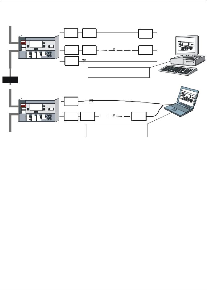
7.4Visualizer for Windows remote operation software (not available yet)
–Operating platform requirements in detail see document 007895
–For details see document ……. (not available yet)
|
|
|
max. length of line |
|
|
|
|
|
dependent on |
|
|
FC/FT |
E3I020 |
Modem |
type of modem |
|
|
Dedicated line |
Modem |
||||
|
|||||
|
|
|
|
||
|
|
|
temporary public |
|
|
|
E3I020 |
Tel. |
telephone line |
Tel. |
|
|
Modem |
|
Modem |
||
|
|
|
|||
|
E3I020 |
(RS232) |
....15m |
|
|
|
|
|
|
||
|
|
Standard PC with keyboard, software |
|||
|
|
’Visualizer for Windows’, |
|
||
C-BUS |
|
|
|
|
|
FC/FT |
|
|
|
|
|
|
B3D021 |
|
|
|
|
|
|
|
temporary public |
|
|
|
E3I020 |
Tel. |
telephone line |
Tel. |
|
|
|
||||
|
Modem |
|
Modem |
||
|
|
e.g. Service Notebook, software |
|
||
|
|
’Visualizer for Windows’, |
|
||
|
|
SWE700A for Windows |
|
||
Visualizer
Remote Operation
(temporary)
18
Siemens Building Technologies |
007836_a_en_--.doc |
Fire & Security Products |
03.2004 |
C-Bus stations
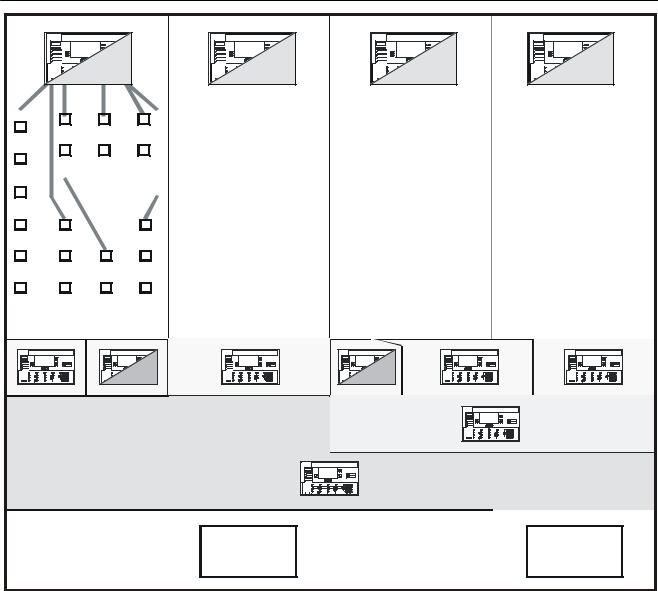
7.5Logical AREAS
FC |
FC |
FC |
FC |
|
|
|
|
|
|
|
|
|
|
|
|
|
|
|
|
|
|
|
|
|
|
|
|
|
|
|
|
|
|
|
|
|
|
|
|
|
|
|
|
|
|
|
|
|
|
|
|
|
|
|
|
|
|
|
|
|
|
|
|
|
|
|
|
|
|
|
|
|
|
|
|
|
|
|
|
|
|
|
|
|
|
|
|
|
|
|
|
|
|
|
|
|
|
|
|
|
|
|
|
|
|
|
|
|
|
|
|
|
|
|
|
|
|
|
|
|
|
|
|
|
|
|
|
|
|
|
|
|
|
|
|
|
|
|
|
|
|
|
|
|
|
|
|
|
|
|
|
|
|
|
|
|
|
|
|
|
|
|
|
|
|
|
|
|
|
|
|
|
|
|
|
|
|
|
|
|
|
|
|
|
|
|
|
|
|
|
|
|
|
|
|
|
|
|
|
|
|
|
|
|
|
|
|
|
|
|
|
|
|
|
|
|
|
|
|
|
|
|
|
|
|
|
|
|
|
|
|
|
|
|
|
|
|
|
|
|
|
|
|
|
|
|
|
|
|
|
|
|
|
|
|
|
|
|
|
|
|
|
|
|
|
|
|
|
|
|
|
|
|
|
|
|
|
|
|
|
|
|
|
|
|
|
|
|
|
|
|
|
|
|
|
|
|
|
|
|
|
|
|
|
|
|
|
|
|
|
|
|
|
|
|
|
|
|
|
|
|
|
|
|
|
|
|
|
|
|
|
|
|
|
|
|
|
|
|
|
|
|
|
|
|
|
|
|
|
|
|
|
|
|
|
|
|
|
|
|
|
|
|
|
|
|
|
|
|
|
|
|
|
|
|
|
|
|
|
|
|
|
|
|
|
|
|
|
|
|
|
|
|
|
|
|
|
|
|
|
|
|
|
|
|
|
|
|
|
|
|
|
|
|
|
|
|
|
|
|
|
|
|
|
|
|
|
|
|
|
|
|
|
|
|
|
|
|
|
|
|
|
|
|
|
|
|
|
|
|
|
|
|
|
|
|
|
|
|
|
|
|
|
|
|
|
|
|
|
|
|
|
|
|
|
|
|
|
|
|
|
|
|
|
|
|
|
|
|
|
|
|
|
|
|
|
|
|
|
|
|
|
|
|
|
|
|
|
|
|
|
|
|
|
|
|
|
|
|
|
|
|
|
|
|
|
|
|
|
|
|
|
|
|
|
|
|
|
|
|
|
|
|
|
|
|
|
|
|
|
|
|
|
|
|
|
|
|
|
|
|
|
|
|
|
|
|
|
|
|
|
|
|
|
|
|
|
|
|
|
|
|
|
|
|
|
|
|
|
|
|
|
|
|
|
|
|
|
|
|
|
|
|
|
|
|
|
|
|
|
|
|
|
|
|
|
|
|
|
|
|
|
|
|
|
|
|
|
|
|
|
|
|
|
|
|
|
|
|
|
|
|
|
|
|
|
|
|
|
|
|
|
|
|
|
|
|
|
|
|
|
|
|
|
|
|
|
|
|
|
|
|
|
|
|
|
|
|
|
|
|
|
|
|
|
|
|
|
|
|
|
|
|
|
|
|
|
|
|
|
|
|
|
|
|
|
|
|
|
|
|
|
|
|
|
|
|
|
|
|
|
|
|
|
|
|
|
|
|
|
|
|
|
|
|
|
|
|
|
|
|
|
|
|
|
|
|
|
|
|
|
|
|
|
|
|
|
|
|
1 |
|
|
|
2 |
3 |
|
4 |
5 |
|
6 |
7 |
8 |
.. |
.. |
.. |
.. |
61 |
62 |
63 |
64 |
|||||||||||||||
AREA |
|
|
|
|
|
|
|
|
|
|
|
|
|
|
|
|
|
|
|
|
|
|
|
|
|
|
|
|
|
|
|
AREA |
|||
FC |
FC |
All AREAS control terminal
|
|
|
|
|
|
|
|
|
|
|
|
|
|
|
|
|
|
|
|
|
|
|
|
|
|
|
|
|
|
|
|
|
|
|
|
|
|
|
|
|
|
|
|
|
|
|
|
|
|
|
|
|
|
|
|
|
|
|
|
|
|
|
|
|
|
|
|
|
|
|
|
|
|
|
|
|
|
|
|
|
FG |
|
|
|
|
|
|
|
|
|
|
FG |
|
||
|
|
|
|
|
|
|
|
|
|
|
|
|
|
|
|
|
|
|
|
|
|
|
|
|
|
|
|
|
|
|
|
–Within one main CPU (FC) max. 4 AREAS can be configured
–CPUs cannot link up with AREAS of other CPUs
–CPU overlapping controls are possible
–Control terminals (FT) can be freely allocated to AREAS as required
–Visibilities on gateways (FG) shall be set per station only, not per AREA!
|
19 |
|
|
Siemens Building Technologies |
007836_a_en_--.doc |
Fire & Security Products |
03.2004 |

Limitations of C-Bus participants
8 Limitations of C-Bus participants
This chapter describes the quantitative limits of the FC700A station.
The selection of the station type depends on the requirements. The following variants are available:
|
|
Flash ROM |
SRAM |
|
|
|
Station type |
Modules |
(2x1024Kx8Bit) |
EPROM set |
RAM set |
||
Soldered |
||||||
|
|
'Program file' |
|
|
||
|
|
|
|
|
||
FC700A |
B3Q700 |
CIY00760 |
4x512Kx8Bit |
– |
– |
|
FT700A |
B3Q700 |
CTY00760 |
4x512Kx8Bit |
– |
– |
|
|
|
|
|
CKQ007.60 |
2 x Z3S070 |
|
FG700A |
E3H020 |
– |
– |
(2x512Kx8Bit) |
||
(2x512Kx8Bit) |
||||||
|
|
|
|
(Assembly ex works) |
||
|
|
|
|
|
8.1Main CPU limits
8.1.1Maximum number of devices
1000 devices (with AMPK=1) per FC700A.
8.1.2Limits in the logical structure
The limits in the logical structure are given by the node-type, by the highest possible CSX number and the maximum amount of display-digits. These limits are given by the system and are independent of the memory capacity.
Table 'Limits of the logical structure'
Maximum rating |
Maximum rating |
Maximum rating |
Maximum rating |
AREAS per STATION |
SECTIONS per AREA |
ZONES per SECTION |
ELEMENTS per ZONE |
... 4 |
…255 |
…255 |
…99 |
|
|
|
International 5: …255 |
8.1.3Maximum number of criteria in zones control 4 and 6
The maximum number of control zones with 16 criteria is limited by 200.
To optimize the performance of your system minimize the number of CPU-overlapping controls as much as possible.
A maximum of 40 CPU-overlapping controls (zone control 6) are admissible per C-Bus.
8.1.4Maximum number of ZONE time channel
Max. 16 ZONES time channel are permitted per station.
20
Siemens Building Technologies |
007836_a_en_--.doc |
Fire & Security Products |
03.2004 |
Limitations of C-Bus participants
8.1.5Maximum number of I-Bus-modules
Table 'Maximum number of I-Bus-modules'
Station type |
FC700A |
I-Bus modules |
... 16 1) ... 8 2) 3) |
1)Limited by software
2)Value based on experience (depends on cabinet size and/or 5V current consumption)
3)Battery charging unit E3C011 counts as one I-Bus module
8.1.6Limits of 5V supply
All I-Bus modules are supplied with 24V and 5V. The available current for the 5V, supplied from main CPU is limited:
'Main CPU' |
Available current |
B3Q700 / E3C011 |
250mA |
Table '5V-Current consumption of I-Bus modules'
I-Bus module |
Current consumption |
I-Bus module |
Current consumption |
|
from 'Main CPU' |
from 'Main CPU' |
|||
|
|
|||
E3M080 |
55mA |
E3G060 |
10mA |
|
E3M111 |
25mA |
E3G070 |
10mA |
|
E3L020 |
10mA |
E3C011 |
12mA |
|
E3L030 |
35mA |
E3I020* |
100mA |
|
E3G050 |
8mA |
E3I040 |
70mA |
*Not an I-Bus module, but supplied via the 'Main CPU'
8.2Control terminal limits (FC/FT)
8.2.1Limitation of visible texts on a FC700A
The number of texts of other stations (i.e. AREAS) that can be displayed on one control terminal is limited by 14'000 texts.
To evaluate how many control panels FC700A can be displayed to one FC700A,
the following calculation must be used:
Twice the number of visible sections (worst case 1000)
+The number of visible ZONES (worst case 1000)
+The number of visible ELEMENTS with element text (worst case 1000)
= Number of texts per FC/FT (worst case 4000)
Example (worst case)
14'000 : 4000 (e.g.) = 3 fully configured FC can be displayed to one FC
8.2.2Limitation of visible texts on a FT700A
The number of texts of other stations (FC700A) that can be displayed on one control terminal is limited by 14'000 texts.
To evaluate how many control panels FC700A can be displayed to one FT700A,
the following calculation must be used:
Twice the number of visible sections (worst case 1000)
+The number of visible ZONES (worst case 1000)
+The number of visible ELEMENTS with element text (worst case 1000)
= Number of texts per FC/FT (worst case 4000)
Example (worst case)
30'000 : 4000 (e.g.) = 7 fully configured FC can be displayed to one FT
|
21 |
|
|
Siemens Building Technologies |
007836_a_en_--.doc |
Fire & Security Products |
03.2004 |
 Loading...