


1-BIT DIGITAL HOME THEATER WITH DVD PLAYER
MODEL
SD-AS10
OPERATION MANUAL
Thank you for purchasing this SHARP product. To obtain the best performance from this product, please read this manual carefully. It will guide you in operating your SHARP product.
SD-AS10 1-Bit Digital Home Theater with DVD Player consisting of
SD-AS10 (main unit and amplifier unit), CP-AS10F (front speakers),
CP-AS10C (center speaker), CP-AS10R (surround speakers) and
CP-AS10W (subwoofer).
SD-AS10
Important Instruction |
- SPECIAL NOTES - |
|
|
SPECIAL NOTES
CAUTION: TO REDUCE THE RISK OF ELECTRIC SHOCK, DO NOT REMOVE COVER (OR BACK).
NO USER-SERVICEABLE PARTS INSIDE. REFER SERVICING TO QUALIFIED SERVICE PERSONNEL.
Explanation of Graphical Symbols:
The lightning flash with arrowhead symbol, within an equilateral triangle, is intended to alert the user to the presence of uninsulated “dangerous voltage” within the product’s enclosure that may be of sufficient magnitude to constitute a risk of electric shock to persons.
The exclamation point within an equilateral triangle is intended to alert the user to the presence of important operating and maintenance (servicing) instructions in the literature accompanying the appliance.
0010
WARNING: TO REDUCE THE RISK OF FIRE OR ELECTRIC SHOCK, DO NOT EXPOSE THIS APPLIANCE TO RAIN OR MOISTURE.
0010
Note to CATV system installer:
This reminder is provided to call the CATV system installer's attention to Article 82040 of the National Electrical Code that provides guidelines for proper grounding and, in particular, specifies that the cable ground shall be connected to the grounding system of the building, as close to the point of cable entry as practical.
NOTE
This equipment has been tested and found to comply with the limits for a Class B digital device, pursuant to Part 15 of the FCC Rules. These limits are designed to provide reasonable protection against harmful interference in a residential installation. This equipment generates, uses, and can radiate radio frequency energy and, if not installed and used in accordance with the instructions, may cause harmful interference to radio communications. However, there is no guarantee that interference will not occur in a particular installation. If this equipment does cause harmful interference to radio or television reception, which can be determined by turning the equipment off and on, the user is encouraged to try to correct the interference by one or more of the following measures:
!Reorient or relocate the receiving antenna.
!Increase the separation between the equipment and receiver.
!Connect the equipment into an outlet on a circuit different from that to which the receiver is connected.
!Consult the dealer or an experienced radio/TV technician for help.
WARNING
FCC Regulations state that any unauthorized changes or modifications to this equipment not expressly approved by the manufacturer could void the user's authority to operate this equipment.
CAUTION:
THIS PRODUCT IS A CLASS 1 LASER PRODUCT.
USE OF CONTROLS OR ADJUSTMENTS OR PERFORMANCE OF PROCEDURES OTHER THAN THOSE SPECIFIED HEREIN MAY RESULT IN HAZARDOUS RADIATION EXPOSURE.
AS THE LASER BEAM USED IN THIS PRODUCT IS HARMFUL TO THE EYES, DO NOT ATTEMPT TO DISASSEMBLE THE CABINET. REFER SERVICING TO QUALIFIED PERSONNEL ONLY.
0207
FOR YOUR RECORDS
For your assistance in reporting this unit in case of loss or theft, please record below the model number and serial number which are located on the bottom of the amplifier unit.
Please retain this information.
Model number .................................................................................
Serial number .................................................................................
Date of purchase .................................................................................
Place of purchase .................................................................................
0407
2

IMPORTANT SAFETY INSTRUCTIONS
1 Read Instructions - All the safety and operating instructions should be read before the product is operated.
2Retain Instructions - The safety and operating instructions should be retained for future reference.
3Heed Warnings - All warnings on the product and in the operating instructions should be adhered to.
4Follow Instructions - All operating and use instructions should be followed.
5Cleaning - Unplug this product from the wall outlet before cleaning. Do not use liquid cleaners or aerosol cleaners. Use a damp cloth for cleaning.
6Attachments - Do not use attachments not recommended by the product manufacturer as they may cause hazards.
7Water and Moisture - Do not use this product near water - for example, near a bath tub, wash bowl, kitchen sink, or laundry tub; in a wet basement; or near a swimming pool; and the like.
8Accessories - Do not place this product on an unstable cart, stand, tripod, bracket, or table. The product may fall, causing serious injury to a child or adult, and serious damage to the product. Use only with a cart, stand, tripod, bracket, or table recommended by the manufacturer, or sold with the product. Any mounting of the product should follow the manufacturer’s instructions, and should use a mounting accessory recommended by the manufacturer.
9A product and cart combination should be moved with
care. Quick stops, excessive force, and uneven surfaces may cause the product and cart combination to overturn.
10Ventilation - Slots and openings in the cabinet are provided for ventilation and to ensure reliable operation of the product and to protect it from overheating, and these openings must not be blocked or covered. The openings should never be blocked by placing the product on a bed, sofa, rug, or other similar surface. This product should not be placed in a built-in installation such as a bookcase or rack unless proper ventilation is provided or the manufacturer’s instructions have been adhered to.
11Power Sources - This product should be operated only from the type of power source indicated on the marking label. If you are not sure of the type of power supply to your home, consult your product dealer or local power company. For products intended to operate from battery power, or other sources, refer to the operating instructions.
12Grounding or Polarization - This product may be equipped with a polarized alternating-current line plug (a plug having one blade wider than the other). This plug will fit into the power outlet only one way. This is a safety feature. If you are unable to insert the plug fully into the outlet, try reversing the plug. If the plug should still fail to fit, contact your electrician to replace your obsolete outlet. Do not defeat the safety purpose of the polarized plug.
Alternate Warnings - This product is equipped with a three-wire grounding-type plug, a plug having a third (grounding) pin. This plug will only fit into a grounding-type power outlet. This is a safety feature. If you are unable to insert the plug into the outlet, contact your electrician to replace your obsolete outlet. Do not defeat the safety purpose of the grounding-type plug.
13Power-Cord Protection - Power-supply cords should be routed so that they are not likely to be walked on or pinched by items placed upon or against them, paying particular attention to cords at plugs, convenience receptacles, and the point where they exit from the product.
14Protective Attachment Plug - The product is equipped with an attachment plug having overload protection. This is a safety feature. See Instruction Manual for replacement or resetting of protective device. If replacement of the plug is required, be sure the service technician has used a replacement plug specified by the manufacturer that has the same overload protection as the original plug.
0109
SD-AS10
Important Instruction |
IMPORTANT SAFETY INSTRUCTIONS - |
|
|
|
|
||
|
|
||
|
|
||
|
|
||
|
|
||
|
|
||
|
|
||
|
|
||
|
|
||
|
|
||
|
|
||
|
- |
|
|
|
|
|
|
|
|
|
|
|
|
|
|
|
|
|
|
|
|
|
|
3
SD-AS10 |
IMPORTANT SAFETY INSTRUCTIONS (continued) |
|
|
Important Instruction |
IMPORTANT SAFETY INSTRUCTIONS - |
|
- |
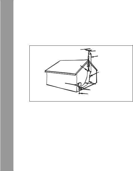
15Outdoor Antenna Grounding - If an outside antenna or cable system is connected to the product, be sure the antenna or cable system is grounded so as to provide some protection against voltage surges and built-up static charges. Article 810 of the National Electrical Code, ANSI/ NFPA 70, provides information with regard to proper grounding of the mast and supporting structure, grounding of the lead-in wire to an antenna discharge unit, size of grounding conductors, location of antennadischarge unit, connection to grounding electrodes, and requirements for the grounding electrode.
Example of antenna grounding as per
National Electrical Code, ANSI/NFPA 70
|
ANTENNA LEAD IN WIRE |
|
GROUND |
|
CLAMP |
|
ANTENNA DISCHARGE UNIT |
|
(NEC SECTION 810-20) |
ELECTRIC |
|
SERVICE |
|
EQUIPMENT |
GROUNDING CONDUCTORS |
|
|
|
(NEC SECTION 810-21) |
|
GROUND CLAMPS |
|
POWER SERVICE GROUNDING |
NEC - NATIONAL ELECTRICAL CODE |
ELECTRODE SYSTEM |
S2898A |
(NEC ART 250, PART H) |
16 Lightning - For added protection for this product during a lightning storm, or when it is left unattended and unused for long periods of time, unplug it from the wall outlet and disconnect the antenna or cable system. This will prevent damage to the product due to lightning and power-line surges.
17Power Lines - An outside antenna system should not be located in the vicinity of overhead power lines or other electric light or power circuits, or where it can fall into such power lines or circuits. When installing an outside antenna system, extreme care should be taken to keep from touching such power lines or circuits as contact with them might be fatal.
18Overloading - Do not overload wall outlets, extension cords, or integral convenience receptacles as this can result in a risk of fire or electric shock.
19 Object and Liquid Entry - Never push objects of any kind into this product through openings as they may touch dangerous voltage points or short-out parts that could result in a fire or electric shock. Never spill liquid of any kind on the product.
20Servicing - Do not attempt to service this product yourself as opening or removing covers may expose you to dangerous voltage or other hazards. Refer all servicing to qualified service personnel.
21Damage Requiring Service - Unplug this product from the wall outlet and refer servicing to qualified service personnel under the following conditions:
a)When the power-supply cord or plug is damaged,
b)If liquid has been spilled, or objects have fallen into the product,
c)If the product has been exposed to rain or water,
d)If the product does not operate normally by following the operating instructions. Adjust only those controls that are covered by the operating instructions as an improper adjustment of other controls may result in damage and will often require extensive work by a qualified technician to restore the product to its normal operation,
e)If the product has been dropped or damaged in any way, and
f)When the product exhibits a distinct change in performance - this indicates a need for service.
22Replacement Parts - When replacement parts are required, be sure the service technician has used replacement parts specified by the manufacturer or have the same characteristics as the original part. Unauthorized substitutions may result in fire, electric shock, or other hazards.
23Safety Check - Upon completion of any service or repairs to this product, ask the service technician to perform safety checks to determine that the product is in proper operating condition.
24Wall or Ceiling Mounting - The product should be mounted to a wall or ceiling only as recommended by the manufacturer.
25Heat - The product should be situated away from heat sources such as radiators, heat registers, stoves, or other products (including amplifiers) that produce heat.
0109
4
"DTS" and "DTS Digital Surround" are registered trademarks of Digital Theater Systems, Inc.
Manufactured under license from Dolby Laboratories. "Dolby", "Pro Logic" and the double-D symbol are trademarks of Dolby Laboratories.
NOTE
Licensed under one or more of U.S. Pat. 4,972,484, 5,214,678, 5,323,396, 5,530,655, 5,539,829, 5,544,247, 5,606,618, 5,610,985, 5,740,317, 5,777,992, 5,878,080 or 5,960,037.
0407
ENERGY STAR® Program Information
Products that have earned the ENERGY STAR® are designed to protect the environment through superior energy efficiency.
ENERGY STAR® is a U.S. registered mark.
0312
The letters in brackets contained in the model number indicate the color of the product only. Operation and specifications are unaffected.
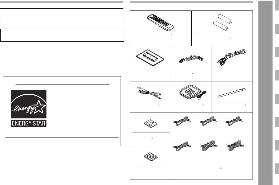
Accessories |
SD-AS10 |
Please confirm that the following accessories are included.
Remote control |
1 |
"AA" size battery (UM/SUM-3, R6, HP- |
|
|
||||||||||
|
|
|
|
|
|
7 or similar) |
2 |
|
|
|
|
|||
(RRMCGA020AWSA) |
|
|
(UBATU0001AWZZ) |
|
|
|
|
|||||||
Main unit stand |
1 |
System connection ca- |
|
Video cable |
1 |
|
General Information |
|
||||||
|
|
|
ble |
1 |
|
|
|
|
|
|
|
|
|
|
(92LSTD5880ASY1) |
(QCNWGA012AWPZ) |
(QCNWGA013AWPZ) |
- Accessories - |
|||||||||||
FM antenna |
1 |
AM loop antenna |
1 |
Button name label |
1 |
|||||||||
(92LFANT1535A) |
(QANTL0014AWZZ) |
(TLABHA006AWSA) |
||||||||||||
|
|
|
White |
|
Green |
|
|
Red |
|
|
|
|||
|
|
|
|
|
|
|
|
|
|
|
||||
Non-slip sheet for main |
(for left front |
|
(for center |
|
|
(for right front |
|
|
|
|||||
speaker) |
|
speaker) |
|
|
speaker) |
|
|
|
|
|||||
unit |
4 |
|
approx. 5 m (16 feet) |
approx. 5 m (16 feet) |
approx. 5 m (16 feet) |
|
|
|||||||
(PCUSGA027AWZZ) |
|
|
|
|
|
|
|
|
|
|
|
|
||
|
|
|
Purple |
|
Blue |
|
|
Gray |
|
|
|
|
||
|
|
|
(for subwoofer) |
(for left surround |
(for right surround |
|
|
|||||||
|
|
|
approx. 5 m (16 feet) |
speaker) |
|
|
speaker) |
|
|
|
|
|||
|
|
|
|
|
approx. 15 m (49 feet) approx. 15 m (49 feet) |
|
|
|||||||
Non-slip sheet for |
|
|
Speaker wire |
6 |
|
|
|
|
|
|
||||
speakers |
20 |
|
|
|
|
|
|
|
|
|
|
|
|
|
(PCUSG0129AWSA) |
|
(QCNWHA006AWZZ) |
|
|
|
|
|
|||||||
Note: |
5 |
Only the above accessories are included. |
|
|
SD-AS10
General Information - Contents -
Contents
Page
" General Information
Precautions . . . . . . . . . . . . . . . . . . . . . . . . . . . . . . . . . . . . . . . . . . . . . . . . . . . . . . . 7 Description of discs . . . . . . . . . . . . . . . . . . . . . . . . . . . . . . . . . . . . . . . . . . . . . . 8, 9 Controls and indicators . . . . . . . . . . . . . . . . . . . . . . . . . . . . . . . . . . . . . . . . 10 - 13
" Preparation for Use
System installation . . . . . . . . . . . . . . . . . . . . . . . . . . . . . . . . . . . . . . . . . . . . . . . . 14 Main unit preparation . . . . . . . . . . . . . . . . . . . . . . . . . . . . . . . . . . . . . . . . . . . . . . 15 System connections . . . . . . . . . . . . . . . . . . . . . . . . . . . . . . . . . . . . . . . . . . . . 16, 17 Antenna connection . . . . . . . . . . . . . . . . . . . . . . . . . . . . . . . . . . . . . . . . . . . . . . . 17 Speaker connection . . . . . . . . . . . . . . . . . . . . . . . . . . . . . . . . . . . . . . . . . . . . . . . 18 TV connection . . . . . . . . . . . . . . . . . . . . . . . . . . . . . . . . . . . . . . . . . . . . . . . . . . . . 19 AC power connection . . . . . . . . . . . . . . . . . . . . . . . . . . . . . . . . . . . . . . . . . . . . . . 20 Remote control . . . . . . . . . . . . . . . . . . . . . . . . . . . . . . . . . . . . . . . . . . . . . . . . . . . 20 General control . . . . . . . . . . . . . . . . . . . . . . . . . . . . . . . . . . . . . . . . . . . . . . . . . . . 21 Setting the clock . . . . . . . . . . . . . . . . . . . . . . . . . . . . . . . . . . . . . . . . . . . . . . . . . . 21
" DVD Operation
Inserting and removing discs
Inserting a disc . . . . . . . . . . . . . . . . . . . . . . . . . . . . . . . . . . . . . . . . . . . . . . . . 22, 23 To remove the disc . . . . . . . . . . . . . . . . . . . . . . . . . . . . . . . . . . . . . . . . . . . . . . . . 23 To exchange other discs while playing a disc . . . . . . . . . . . . . . . . . . . . . . . . . . 23
Playing a disc
Playback . . . . . . . . . . . . . . . . . . . . . . . . . . . . . . . . . . . . . . . . . . . . . . . . . . . . . . 24, 25 To resume playback after stopping (resume play) . . . . . . . . . . . . . . . . . . . . . . . 25 Changing the progressive scan select mode . . . . . . . . . . . . . . . . . . . . . . . . . . . 25
Basic operation |
|
Fast forward/Fast reverse (search) . . . . . . . . . . . . . . . . . . . . . . . . . . . . . . . . . . . |
26 |
To locate the beginning of a chapter (track) (skip) . . . . . . . . . . . . . . . . . . . . . . |
27 |
To start playback from the desired point (direct play) . . . . . . . . . . . . . . . . . . . . |
27 |
To play by specifying time (time search) . . . . . . . . . . . . . . . . . . . . . . . . . . . . . . |
27 |
Useful operation
To change the subtitle language . . . . . . . . . . . . . . . . . . . . . . . . . . . . . . . . . . . . . 28 To change the audio language (audio output) . . . . . . . . . . . . . . . . . . . . . . . . . . 28 To select a title from the top menu of the disc . . . . . . . . . . . . . . . . . . . . . . . . . . 29 To select a subtitle or audio language from the disc menu . . . . . . . . . . . . . . . 29 Still picture/Frame advance . . . . . . . . . . . . . . . . . . . . . . . . . . . . . . . . . . . . . . . . . 29 Slow-motion play . . . . . . . . . . . . . . . . . . . . . . . . . . . . . . . . . . . . . . . . . . . . . . . . . 29 To change the angle . . . . . . . . . . . . . . . . . . . . . . . . . . . . . . . . . . . . . . . . . . . . . . . 30 To zoom images (zoom) . . . . . . . . . . . . . . . . . . . . . . . . . . . . . . . . . . . . . . . . . . . . 30 To play repeatedly (repeat play) . . . . . . . . . . . . . . . . . . . . . . . . . . . . . . . . . . . . . . 31 To play the contents between the specified points repeatedly (A-B repeat) . . 31 To change the display on TV screen . . . . . . . . . . . . . . . . . . . . . . . . . . . . . . . . . . 32 To change the display on the main unit . . . . . . . . . . . . . . . . . . . . . . . . . . . . . . . 32
Page
" CD, CD-R and CD-RW Operation
Playing a CD
To start playback from the desired point (direct play) . . . . . . . . . . . . . . . . . . . . 33 To play by specifying time (time search) . . . . . . . . . . . . . . . . . . . . . . . . . . . . . . 33 To play in the desired order (programmed play) . . . . . . . . . . . . . . . . . . . . . . . . 34 To play in random order (random play) . . . . . . . . . . . . . . . . . . . . . . . . . . . . . . . . 34
MP3/WMA and JPEG disc operation
Playback on the MP3/WMA and JPEG menu screen . . . . . . . . . . . . . . . . . . . . . 35 To play in the desired order (programmed play) . . . . . . . . . . . . . . . . . . . . . . . . 36 Zoom function . . . . . . . . . . . . . . . . . . . . . . . . . . . . . . . . . . . . . . . . . . . . . . . . . . . . 37 Rotating a picture . . . . . . . . . . . . . . . . . . . . . . . . . . . . . . . . . . . . . . . . . . . . . . . . . 37
" Radio Operation
Listening to the radio . . . . . . . . . . . . . . . . . . . . . . . . . . . . . . . . . . . . . . . . . . . 38, 39
" Advanced Features
Enjoying surround sound (sound mode) . . . . . . . . . . . . . . . . . . . . . . . . . . 40 - 42 Changing the default settings of the amplifier . . . . . . . . . . . . . . . . . . . . . . 43 - 45 Changing the initial setting of DVD . . . . . . . . . . . . . . . . . . . . . . . . . . . . . . . 46 - 49 Setting the timer. . . . . . . . . . . . . . . . . . . . . . . . . . . . . . . . . . . . . . . . . . . . . . . . 50, 51 Operations after setting the timer . . . . . . . . . . . . . . . . . . . . . . . . . . . . . . . . . . . . 52 Sleep timer . . . . . . . . . . . . . . . . . . . . . . . . . . . . . . . . . . . . . . . . . . . . . . . . . . . . . . . 53 Operating the connected TV . . . . . . . . . . . . . . . . . . . . . . . . . . . . . . . . . . . . . 54, 55 Connecting other equipment . . . . . . . . . . . . . . . . . . . . . . . . . . . . . . . . . . . . 56 - 58
" References
Language code list . . . . . . . . . . . . . . . . . . . . . . . . . . . . . . . . . . . . . . . . . . . . . . . . 58 Error indicators and warnings . . . . . . . . . . . . . . . . . . . . . . . . . . . . . . . . . . . . . . . 59 Troubleshooting chart . . . . . . . . . . . . . . . . . . . . . . . . . . . . . . . . . . . . . . . . . . 60, 61 Maintenance . . . . . . . . . . . . . . . . . . . . . . . . . . . . . . . . . . . . . . . . . . . . . . . . . . . . . 62 Optional accessories . . . . . . . . . . . . . . . . . . . . . . . . . . . . . . . . . . . . . . . . . . . . . . 62 Specifications . . . . . . . . . . . . . . . . . . . . . . . . . . . . . . . . . . . . . . . . . . . . . . . . . 62, 63
CONSUMER LIMITED WARRANTY . . . . . . . . . . . . . . . . . . . . . . . . . . . .Back cover
Icons used in this operation manual
Some functions may not be available depending on discs. The following icons indicate the discs that can be used in the section.

 ... DVD-Video discs and DVD-R/DVD-RW for NTSC system.

 ... Audio CDs.

 ... CD-R/CD-RW with MP3 recording.

 ... CD-R/CD-RW with WMA recording.

 ... CD-R/CD-RW with JPEG recording.
6
Precautions
" General
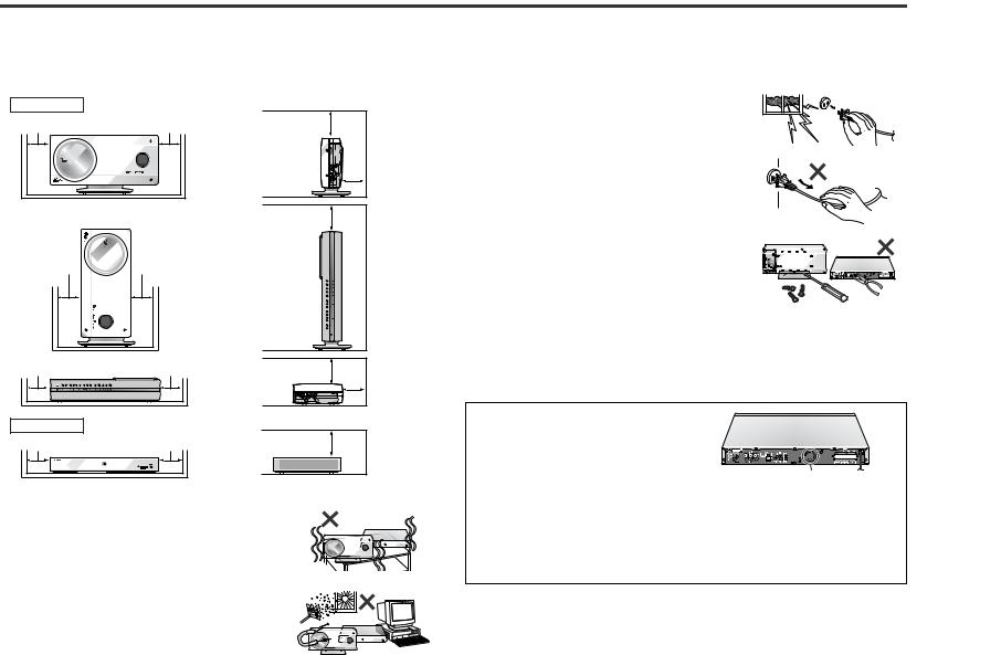
!Please ensure that the equipment is positioned in a well-ventilated area and that there is at least 4" (10 cm) of free space along the sides and back. There must also be a minimum of 6" (15 cm) of free space on the top of the unit.
Main unit |
|
4" (10 cm) Position A 4" (10 cm) |
6" (15 cm) |
4" (10 cm) |
Position B |
6" (15 cm) |
4" (10 cm) |
4" (10 cm) |


 4" (10 cm)
4" (10 cm) |
Position C |
4" (10 cm) |
Amplifier unit |
|
|
4" (10 cm) |
|
4" (10 cm) |
6" (15 cm)
4" (10 cm) |
6" (15 cm)

 4" (10 cm)
!Use the unit on a firm, level surface free from vibration.
!Keep the unit away from direct sunlight, strong magnetic fields, excessive dust, humidity and electronic/ electrical equipment (home computers, facsimiles, etc.) which generate electrical noise.
!Do not place anything on top of the unit.
!Do not expose the unit to moisture, to temperatures higher than 140°F (60°C) or to extremely low temperatures.
!If the unit does not work properly, unplug and plug it
in again. Then turn on the unit.
! In case of an electrical storm, unplug the unit for safety.
!Hold the AC power plug by the head when removing it from the AC outlet, as pulling the cord can damage
internal wires.
!Do not remove the outer cover, as this may result in electric shock. Refer internal service to your lo-
cal SHARP service facility.
! This unit should only be used within the range of 41°F - 95°F (5°C - 35°C).
Warning:
The voltage used must be the same as that specified by this unit. Using this product with a higher voltage other than that specified is dangerous and may result in a fire or other types of accident, causing damage. SHARP will not be held responsible for any damage resulting from the use of this unit with a voltage other than that specified.
Cooling fan
This amplifier unit is fitted with a cooling fan at the rear for improved cooling. Do not
cover the opening in this section with any obstacles.
Cooling fan
Caution:
!The amplifier unit will get warm while being used. Do not touch the warm areas of the amplifier unit for prolonged periods to avoid damage to you.
!This amplifier unit contains an automatic protection circuit, which protects the amplifier unit from being damaged. All speaker outputs are muted when this circuit is activated. Should the unit stop operating, first check the speaker terminals for shorted wires, then press the POWER button to turn on the main unit.
" Volume control
The sound level at a given volume setting depends on speaker efficiency, location and various other factors. It is advisable to avoid exposure to high volume levels, which occurs while turning the unit on with the volume control setting up high, or while continually listening at high volumes.
SD-AS10
General Information |
- Precautions - |
|
|
|
|
||
|
|
||
|
|
||
|
|
||
|
|
||
|
|
||
|
|
||
|
|
||
|
|
||
|
|
|
|
|
|
|
|
|
|
|
|
|
|
|
|
|
|
|
|
|
|
|
|
7
SD-AS10
General Information - Description of discs -
Description of discs
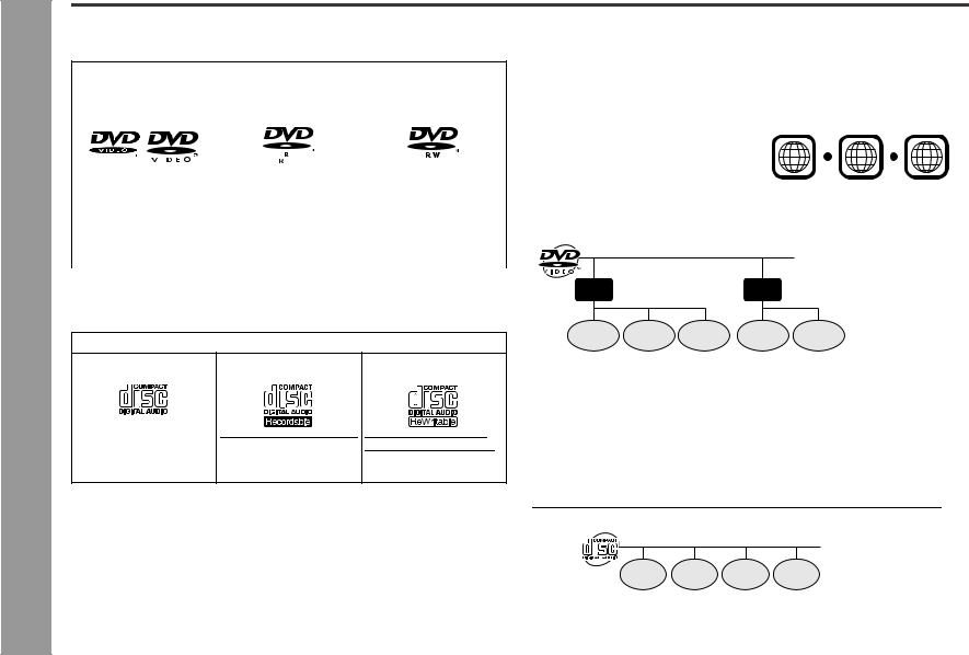
" Types of playable discs
The unit can play back discs bearing any of the following marks:
DVD
|
DVD-Video Disc for NTSC |
DVD-R for NTSC system |
DVD-RW for NTSC sys- |
|||
|
|
|
|
|
|
tem |
|
system |
|
||||
|
|
|
4.7 |
|
||
|
|
|
|
|
|
|
|
|
|
|
|
|
|
|
|
|
|
|
Recorded in the video |
Recorded in the video |
|
|
|
|
|
mode (*) |
mode (*) |
|
|
|
|
|
|
Discs recorded in VR |
|
|
|
|
|
|
mode (Video Recording |
|
|
|
|
|
|
format) cannot be played |
|
|
|
|
|
|
back. |
|
|
|
|
|
|
|
Some DVD discs may not function as described in the manual. See the disc jacket for restrictions.
CD
Audio CD |
Audio CD-R |
Audio CD-RW |
Or CD-R recorded in MP3/ Or CD-RW recorded in WMA/JPEG format (*) MP3/WMA/JPEG format
(*)
(*)Some discs may not play properly due to the status of the equipment used for recording, characteristics of the discs, scratches, dirt, or dirty optical pickup lens.
" DVD-Video
A popular type of DVD disc of the same size as a CD, mainly containing video images.
Region number
DVD discs are programmed with region numbers indicating countries in which they can be played. This system can play discs with region number "1" or "ALL".
Region number (playable area number)
1 |
1 2 |
6 |
ALL |
|
|
|
Title and chapter
DVD-Video discs are divided into "titles" and "chapters". If the disc has more than one movie on it, each movie is a separate "title". "Chapters" are subdivisions of titles.
Title 1 |
Title 2 |
Chapter 1 Chapter 2 Chapter 3 |
Chapter 1 Chapter 2 |
" DVD-R/DVD-RW playback
!You can play DVD-R and DVD-RW discs recorded in the video mode.
!Before playing DVD-R/DVD-RW discs with this unit, finalize them with the equipment used for recording.
" CD
Track
The audio CD is composed of "tracks". Tracks are equivalent to songs on a CD.
Track 1 Track 2 Track 3 Track 4
8
" MP3/WMA/JPEG format on CD-R/CD-RW
An MP3 file is an audio data compressed in the MPEG 1 audio layer 3 format. MP3 files have the extension ".mp3". (Files with the extension ".mp3" may not play, or noise may occur during playback if not recorded in the MP3 format.)
WMA is an audio file format developed by Microsoft with the ".wma" extension. This type of audio file is recorded through Microsoft Windows operating system.
A JPEG file is still image data compressed in the JPEG (Joint Photographic Experts Group) format. JPEG files have the extension ".jpg".
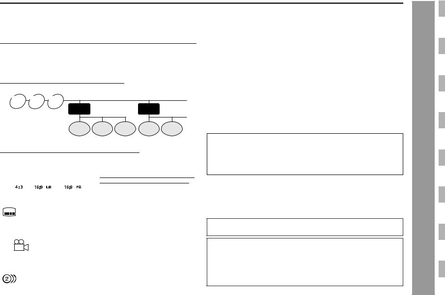
Folder and file
MP3/WMA/JPEG discs consist of "folders" and "files".
MP3 WMA JPEG disc disc disc
Folder 1 |
Folder 2 |
" Discs that cannot be played
! DVDs without the region number "1" or |
! DVD-Audio |
|
|
|
! SACD |
|
"ALL" |
|
! DVDs with PAL system |
! CDG |
|
! DVDs with SECAM system |
! Video CD |
|
! DVDs with MPEG sound |
! Photo CD |
|
! DVD-ROM |
! CD-ROM |
|
! DVD-RAM |
! Discs recorded in special formats, etc. |
|
!The discs above cannot be played at all, or no sound is heard although images appear on the screen or vice versa.
!Faulty playback may damage the speakers and can have an adverse effect on your hearing when played at high volume settings.
!This DVD player adopts the NTSC system. Discs that were made in foreign countries may not be played back. Check the recording system before purchasing discs.
!You cannot play illegally produced discs.
File 1 |
File 2 |
File 3 |
File 1 |
File 2 |
" Icons used on DVD discs
Check the icons of the DVD jacket before playing your discs.
|
|
|
|
|
|
Display |
|
|
Description |
|||||||||||
|
|
|
|
|
|
|
|
|
|
|
|
|
|
|
|
|
|
|||
Format recorded on the DVD |
|
To adapt the video format to the connect- |
||||||||||||||||||
|
|
|
|
|
|
|
|
|
|
|
|
|
|
|
|
|
|
ed TVs ("wide-screen TV" or "4:3 size |
||
|
|
|
|
|
|
|
|
|
|
|
|
|
|
|
|
|
|
TV"). |
|
|
|
|
|
|
|
|
|
|
|
|
|
|
|
|
|
|
|
|
|
|
|
Type of subtitles recorded |
|
Recorded subtitle languages. |
||||||||||||||||||
2 |
|
Example: |
|
You can select a subtitle language. |
||||||||||||||||
|
1: English |
|
|
|
|
|||||||||||||||
|
|
|
|
|
|
|||||||||||||||
|
|
2: Japanese |
|
|
|
|
||||||||||||||
|
|
|
|
|
|
|
|
|
|
|
|
|
|
|
|
|
|
|||
Number of camera angles |
|
Number of angles recorded on the DVD. |
||||||||||||||||||
|
|
|
|
|
|
|
|
|
|
|
|
|
|
|
|
|
|
You can view scenes from different an- |
||
|
2 |
|
|
|
|
|
|
|
|
|
|
|
|
|
|
|
gles. |
|||
|
|
|
|
|
|
|
|
|
|
|
|
|
|
|
|
|
|
|
||
|
|
|
|
|
|
|
|
|
|
|
|
|
|
|
|
|
|
|||
Number of audio tracks and audio |
|
The number of audio tracks and audio re- |
||||||||||||||||||
recording systems |
|
cording systems are indicated. |
||||||||||||||||||
|
|
Example: |
|
! You can change the audio language. |
||||||||||||||||
|
|
1: Original <English> (Dolby Dig- |
! Audio and recording system vary de- |
|||||||||||||||||
|
|
ital 5.1 Surround) |
|
pending on the DVD. Check them in |
||||||||||||||||
|
|
2: Japanese (Dolby Digital 2 ch) |
|
the DVD's manual. |
||||||||||||||||
|
|
|
|
|
|
|||||||||||||||
|
|
|
|
|
|
|
|
|
|
|
|
|
|
|
|
|
|
|
|
|
Copyright Information:
!Unauthorized copying, broadcast, public display, transmission, public performance and rental (regardless of whether or not such activities are for profit) of disc contents are prohibited by law.
!This system is equipped with copy protection technology that causes substantial degradation of images when the contents of a disc are copied to a video tape.
Copy Protection:
This unit supports Macrovision copy protection.
On DVD discs that include a copy protection code, if the contents of the DVD disc are copied using a VCR, the copy protection code prevents the videotape copy from playing normally.
Apparatus Claims of U.S. Patent Nos. 4,631,603, 4,577,216, 4,819,098 and 4,907,093 licensed for limited viewing uses only.
This product incorporates copyright protection technology that is protected by method claims of certain U.S. patents and other intellectual property rights owned by Macrovision Corporation and other rights owners.
Use of this copyright protection technology must be authorized by Macrovision Corporation, and is intended for home and other limited viewing uses only unless otherwise authorized by Macrovision Corporation.
Reverse engineering or disassembly is prohibited.
0407
SD-AS10
General Information - Description of discs -
9
SD-AS10
Information |
and indicators - |
General |
- Controls |
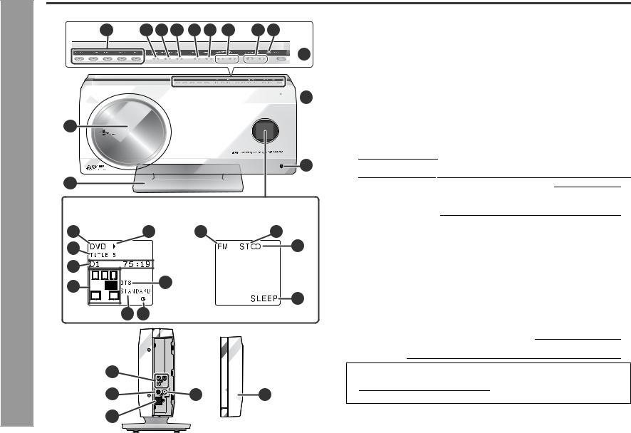
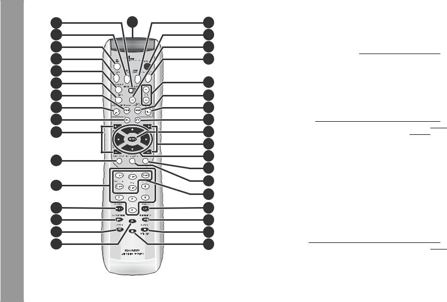
Controls and indicators
1 |
2 |
3 |
4 |
5 |
6 |
7 |
8 |
9 |

 10
10


 11
11
12 |
9 |
13 |
(Display) Indicators vary according to operations.
14 |
DVD/CD |
18 |
22 |
TUNER 23 |
|
|
15 |
|
|
|
|
|
24 |
16 |
L |
C R |
|
L |
C R |
|
|
19 |
|
||||
17 |
LFE |
SW |
|
SW |
|
|
SL |
SR |
|
SL |
SR |
25 |
|
|
|
|||||
|
|
|
|
|
|
|
|
|
20 21 |
|
|
|
|
(Right side) |
|
|
|
|
||
|
|
26 |
|
|
|
|
|
|
27 |
|
29 |
30 |
|
|
|
28 |
|
|
|
|
" Main unit |
|
|
Reference page |
1. Disc Number Select Buttons . . . . . . . . . . . . . . . . . . . . |
.22, 24, 34, 61 |
2. Disc Compartment Open/Close Button . . . . . . . . . . . . |
. . . . . . . . . .22 |
3. Function Button . . . . . . . . . . . . . . . . . . . . . . . . . . . . . . . |
. . . . . . . . . .56 |
4. Tuner (Band) Button . . . . . . . . . . . . . . . . . . . . . . . . . . . |
. . . . . . . . . .38 |
5. Play Button . . . . . . . . . . . . . . . . . . . . . . . . . . . . . . . . . . . |
. . . . . . . . . .24 |
6. Stop Button . . . . . . . . . . . . . . . . . . . . . . . . . . . . . . . . . . |
.22, 25, 57, 61 |
7.Chapter (Track) Skip Up and Down, Search or Tuning Up and Down buttons 26, 27, 38
8. Volume Up and Down Buttons . . . . . . . . . . . . . . . . . . . . . . . . . . |
. . .21 |
9. Remote Sensor . . . . . . . . . . . . . . . . . . . . . . . . . . . . . . . . . . . . . . |
. . .20 |
10.Power Button . . . . . . . . . . . . . . . . . . . . . . . . . . . . . . . . . . . . . . . . |
20, 61 |
11.Timer Set Indicator . . . . . . . . . . . . . . . . . . . . . . . . . . . . . . . . . . . |
. . .51 |
12.Disc Compartment . . . . . . . . . . . . . . . . . . . . . . . . . . . . . . . . . . . . |
. . .22 |
13.Main Unit Stand . . . . . . . . . . . . . . . . . . . . . . . . . . . . . . . . . . . . . . |
. . .15 |
14.Function Indicator . . . . . . . . . . . . . . . . . . . . . . . . . . . . . . . . . . . . . . .32 15.Track, Title, Chapter, Total Information Indicator . . . . . . . . . . . . . .32 16.Time and Present Disc Indicator . . . . . . . . . . . . . . . . . . . . . . . . . . .32 17.Speaker Indicators . . . . . . . . . . . . . . . . . . . . . . . . . . . . . . . . . . . . . . .42 18.Operation Indicator . . . . . . . . . . . . . . . . . . . . . . . . . . . . . . . . . . . . . .32 19.Audio Signal Indicator . . . . . . . . . . . . . . . . . . . . . . . . . . . . . . . . . . . .42 20.Surround Indicator . . . . . . . . . . . . . . . . . . . . . . . . . . . . . . . . . . . . . . .32 21.Timer Indicator . . . . . . . . . . . . . . . . . . . . . . . . . . . . . . . . . . . . . . . . . .52
22.Tuner (Band) Indicator . . . . . . . . . . . . . . . . . . . . . . . . . . . . . . . . . . . .38 23.FM Stereo Mode Indicator . . . . . . . . . . . . . . . . . . . . . . . . . . . . . . . . .38 24.FM Stereo Receiving Indicator . . . . . . . . . . . . . . . . . . . . . . . . . . . . .38 25.Sleep Indicator . . . . . . . . . . . . . . . . . . . . . . . . . . . . . . . . . . . . . . . . . .53
26.Component Video Output Jacks . . . . . . . . . . . . . . . . . . . . . . . . . . .19 27.S-video Output Jack . . . . . . . . . . . . . . . . . . . . . . . . . . . . . . . . . . . . .19 28.System Connection Jack (to amplifier unit) . . . . . . . . . . . . . . . . . .17 29.Video Output Jack . . . . . . . . . . . . . . . . . . . . . . . . . . . . . . . . . . . . . . .19 30.Side Cover . . . . . . . . . . . . . . . . . . . . . . . . . . . . . . . . . . . . . . . . . . . . .19
Notes:
!Make sure to attach the main unit stand (see page 15).
!How to open side cover (see page 17).
10
" Amplifier unit
(Front) |
1 |
2 |
|||||
|
|
|
|
|
|
|
|
|
|
|
|
|
|
|
|
|
|
|
|
|
|
|
|
(Rear)
3 |
4 |
5 |
6 |
7 |
8 |
9 |
10 |
11 |
" Front/Surround speakers
(Front) (Rear)
|
|
|
|
1 |
|
|
2 |
|
|
|
|
|
|
||||
|
|
|
|
|
|
|
Reference page |
|
1. Speaker |
|
|
||||||
|
|
|
|
|||||
2. Speaker Terminals . . . . . . . . . . . . . . . . . |
. . . . . . . . 18. . . . . . . . . . . . . |
|||||||
" Center speaker
|
|
|
|
|
|
|
|
|
|
|
|
|
|
|
|
|
|
|
|
|
|
|
|
|
|
(Front) |
|
(Rear) |
|
|
|
|
|
|
|
|
|
|
|
|
|
|
|
|
|
|
|
|
|
|
|
|
|
|
|
|
|
|
|
|
|
|
|
|
|
|
|
|
|
|
|
|
|
|
|
|
|
|
|
|
|
|
|
|
|
|
|
|
|
|
|
|
|
|
|
|
|
|
|
|
|
|
|
|
|
|
|
|
|
|
|
|
|
|
|
|
|
|
|
|
|
|
|
|
|
|
|
|
|
|
|
|
|
|
|
|
|
|
|
|
|
|
|
|
|
|
|
|
|
|
|
|
|
|
|
|
|
|
|
|
|
|
|
|
|
|
|
|
|
|
|
|
|
|
|
|
|
|
|
|
|
|
|
|
|
|
|
|
|
|
|
|
|
|
|
|
|
|
|
|
|
|
|
|
|
|
|
|
|
|
|
|
|
|
|
|
|
|
|
|
|
|
|
|
|
|
|
|
|
|
|
|
|
|
|
|
|
|
|
|
|
|
|
|
|
|
|
|
|
|
|
|
|
|
|
|
|
|
|
|
|
|
|
|
|
|
|
|
|
|
|
|
|
|
|
|
|
|
12 |
13 |
14 |
15 |
16 |
|
Reference page |
1. Power Indicator . . . . . . . . . . . . . . . . . . . . . . . . . . . . . . . |
. . . . . . . . . . 20 |
2. Headphone Jack . . . . . . . . . . . . . . . . . . . . . . . . . . . . . . |
. . . . . . . . . . 58 |
3. FM 75 Ohm Antenna Jack . . . . . . . . . . . . . . . . . . . . . . . |
. . . . . . . . . . 17 |
4. AM Antenna Ground Terminal . . . . . . . . . . . . . . . . . . . |
. . . . . . . . . . 17 |
5. AM Antenna Terminal . . . . . . . . . . . . . . . . . . . . . . . . . . |
. . . . . . . . . . 17 |
6. System Connection Jack (to main unit) . . . . . . . . . . . |
. . . . . . . . . . 17 |
7. Coaxial Digital Audio Input Jack . . . . . . . . . . . . . . . . . |
. . . . . . . . . . 57 |
8. Optical Digital Audio Input Jack . . . . . . . . . . . . . . . . . . |
. . . . . . . . . . 56 |
9. Optical Digital Audio Output Jack . . . . . . . . . . . . . . . . |
. . . . . . . . . . 57 |
10.Speaker Terminals . . . . . . . . . . . . . . . . . . . . . . . . . . . . . |
. . . . . . . . . . 18 |
11.AC Power Cord . . . . . . . . . . . . . . . . . . . . . . . . . . . . . . . . |
. . . . . . . . . . 20 |
12.Subwoofer Pre Output Jack . . . . . . . . . . . . . . . . . . . . . |
. . . . . . . . . . 58 |
(Connect a commercially available subwoofer with a built-in amplifier.)
13.TV Audio Input Jacks . . . . . . . . . . . . . . . . . . . . . . . . . . . . . . . . . . . . 56 14.VCR Audio Input Jacks . . . . . . . . . . . . . . . . . . . . . . . . . . . . . . . . . . . 56 15.VCR Audio Output Jacks . . . . . . . . . . . . . . . . . . . . . . . . . . . . . . . . . 56 16.Cooling Fan . . . . . . . . . . . . . . . . . . . . . . . . . . . . . . . . . . . . . . . . . . . . . 7
1 |
|
|
|
|
|
2 |
|||||||||||
1. Speaker |
|
|
|
|
|
|
|
|
Reference page |
||||||||
|
|
|
|
|
|
|
|
|
|||||||||
2. Speaker Terminals . . . . . |
. . 18. . . . . . . . . . . . . . . . . . . . . . . . . . . . . . . |
||||||||||||||||
" Subwoofer |
|
|
|
|
|
|
|
|
|
||||||||
|
|
|
(Front) |
|
|
|
(Rear) |
||||||||||
|
|
|
|
|
|
|
|
|
|
1 |
|
|
|
|
|
|
|
|
|
|
|
|
|
|
|
|
|
|
|
|
|
|
|
|
|
|
|
|
|
|
|
|
|
|
|
|
|
|
|
|
|
|
|
|
|
|
|
|
|
|
|
|
|
|
|
|
|
|
|
|
|
|
|
|
|
|
|
|
|
|
|
|
|
|
|
|
|
|
|
|
|
|
|
|
|
|
|
|
|
|
|
|
|
|
|
|
|
2 |
3 |
||
|
|
|
Reference page |
1. Woofer |
|
||
2. Bass Reflex Duct |
|
||
3. Speaker Terminals . . . . . . . . . . . . . . . . . . . . . |
. . . . . . . . . . . . . . . . . 18 |
||
SD-AS10
Information |
and indicators - |
|
|
|
|
||
|
|
||
|
|
||
|
|
||
|
|
||
|
|
||
|
|
||
|
|
||
General |
- Controls |
|
|
|
|
||
|
|
||
|
|
|
|
|
|
|
|
|
|
|
|
|
|
|
|
|
|
|
|
11
SD-AS10 |
Controls and indicators (continued) |
|
|
Information |
and indicators - |
General |
- Controls |
2 |
1 |
18 |
3 |
|
19 |
4 |
|
20 |
5 |
|
21 |
6 |
|
|
7 |
|
22 |
8 |
|
23 |
9 |
|
24 |
10 |
|
25 |
11 |
|
26 |
|
|
27 |
12 |
|
28 |
|
29 |
|
|
|
|
13 |
|
30 |
|
31 |
|
|
|
|
14 |
|
32 |
15 |
|
33 |
16 |
|
34 |
17 |
|
35 |
" Remote control
Set the MODE 1/MODE 2 switch to MODE 1 and press the following buttons.
Reference page
1. Remote Control Transmitter . . . . . . . . . . . . . . . . . . . . . . . . . . . . . . .20 2. MODE 1/MODE 2 Switch . . . . . . . . . . . . . . . . . . . . . . . . . . . . . . . . . .13 3. Function Select Button (DIG1/DIG2) . . . . . . . . . . . . . . . . . . . . . . . .56 4. Disc Compartment Open/Close Button . . . . . . . . . . . . . . . . . . . . . .22 5. Function Select Button (VCR/TV) . . . . . . . . . . . . . . . . . . . . . . . . . . .56 6. TV On/Stand-by Button . . . . . . . . . . . . . . . . . . . . . . . . . . . . . . . . . . .54 7. TV/Video Select Button . . . . . . . . . . . . . . . . . . . . . . . . . . . . . . . . . . .54 8. Stereo (2 channel) Select Button . . . . . . . . . . . . . . . . . . . . . . . . . . .41 9. Multi Channel Select Button . . . . . . . . . . . . . . . . . . . . . . . . . . . . . . .40 10.Menu Button . . . . . . . . . . . . . . . . . . . . . . . . . . . . . . . . . . . . . . . . . . . .29 11.TV Volume Up and Down Buttons . . . . . . . . . . . . . . . . . . . . . . . . . .54 12.Direct Select Button . . . . . . . . . . . . . . . . . . . . . . . . . . . . . . . . . . . . .27 13.Direct Number Buttons . . . . . . . . . . . . . . . . . . . . . . . . . . . . . . . . . . .27
14.Review/Tuning Down Button . . . . . . . . . . . . . . . . . . . . . . . . . . . .26, 38 15.Chapter (track) Skip Down/Tuner Preset Down Button . . . . . .27, 39 16.Repeat Play Button . . . . . . . . . . . . . . . . . . . . . . . . . . . . . . . . . . . . . .31 17.Play Button . . . . . . . . . . . . . . . . . . . . . . . . . . . . . . . . . . . . . . . . . . . . .24 18.Tuner (Band) Button . . . . . . . . . . . . . . . . . . . . . . . . . . . . . . . . . . . . .38 19.Power Button . . . . . . . . . . . . . . . . . . . . . . . . . . . . . . . . . . . . . . . . . . .20 20.Mute Button . . . . . . . . . . . . . . . . . . . . . . . . . . . . . . . . . . . . . . . . . . . .21 21.Timer/Sleep/Clock Button . . . . . . . . . . . . . . . . . . . . . . . . . . .21, 51, 53 22.TV Channel Up and Down Buttons . . . . . . . . . . . . . . . . . . . . . . . . . .54 23.Program Button . . . . . . . . . . . . . . . . . . . . . . . . . . . . . . . . . . . . . . . . .34 24.Random Play Button . . . . . . . . . . . . . . . . . . . . . . . . . . . . . . . . . . . . .34 25.Return Button . . . . . . . . . . . . . . . . . . . . . . . . . . . . . . . . . . . . . . . . . . .44 26.Enter Button . . . . . . . . . . . . . . . . . . . . . . . . . . . . . . . . . . . . . . . . . . . .21 27.Volume Up and Down Buttons . . . . . . . . . . . . . . . . . . . . . . . . . . . . .21 28.Cursor Buttons . . . . . . . . . . . . . . . . . . . . . . . . . . . . . . . . . . . . . . . . . .21 29.Disc Select Button . . . . . . . . . . . . . . . . . . . . . . . . . . . . . . . . . . . . . . .22 30.On Screen Button . . . . . . . . . . . . . . . . . . . . . . . . . . . . . . . . . . . . . . .32 31.Disc Number Select Buttons . . . . . . . . . . . . . . . . . . . . . . . . . . . . . .22 32.Cue/Tuning Up Button . . . . . . . . . . . . . . . . . . . . . . . . . . . . . . . . .26, 38 33.Chapter (Track) Skip Up/Tuner Preset Up Button . . . . . . . . . . .27, 39 34.DVD Still Frame Advance/Disc Pause Button . . . . . . . . . . . . . .25, 29 35.Stop Button . . . . . . . . . . . . . . . . . . . . . . . . . . . . . . . . . . . . . .22, 25, 57
12
1 |
7 |
|
8 |
||
|
||
2 |
9 |
|
3 |
||
10 |
||
4 |
||
11 |
||
5 |
||
12 |
||
|
||
6 |
13 |
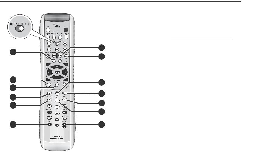
" Remote control
Set the MODE 1/MODE 2 switch to MODE 2 and press the following buttons (indicated in blue). Available operations change.
|
Reference page |
1. DVD Top Menu Button . . . . . . . . . . . . . . . . . . . . . . . . . . |
. . . . . . . . . . 29 |
2. Clear Button . . . . . . . . . . . . . . . . . . . . . . . . . . . . . . . . . . . |
. . . . . . . . . 39 |
3. Display (Dimmer) Button . . . . . . . . . . . . . . . . . . . . . . . . |
. . . . . . 21, 32 |
4. DVD Angle Button . . . . . . . . . . . . . . . . . . . . . . . . . . . . . . |
. . . . . . . . . 30 |
5. Progressive Scan Mode Select Button . . . . . . . . . . . . . |
. . . . . . . . . 25 |
6. A - B Repeat Button . . . . . . . . . . . . . . . . . . . . . . . . . . . . |
. . . . . . . . . 31 |
7. DVD Setup Button . . . . . . . . . . . . . . . . . . . . . . . . . . . . . . |
. . . . . . . . . 46 |
8. Amplifier Setup Button . . . . . . . . . . . . . . . . . . . . . . . . . . |
. . . . . . . . . 44 |
9. DVD Zoom Button . . . . . . . . . . . . . . . . . . . . . . . . . . . . . . |
. . . . . . . . . 30 |
10.DVD Audio Language Select Button . . . . . . . . . . . . . . . |
. . . . . . . . . 28 |
11.DVD Subtitle Button . . . . . . . . . . . . . . . . . . . . . . . . . . . . |
. . . . . . . . . 28 |
12.Dolby Virtual Speaker button . . . . . . . . . . . . . . . . . . . . . |
. . . . . . . . . 41 |
13.DVD Slow Button . . . . . . . . . . . . . . . . . . . . . . . . . . . . . . . |
. . . . . . . . . 29 |
Note:
In "MODE 2", you can use buttons other than the above for the same operations as in "MODE 1".
SD-AS10
Information |
and indicators - |
|
|
|
|
||
|
|
||
|
|
||
|
|
||
|
|
||
|
|
||
|
|
||
|
|
||
General |
- Controls |
|
|
|
|
||
|
|
||
|
|
|
|
|
|
|
|
|
|
|
|
|
|
|
|
|
|
|
|
13
SD-AS10
Preparation for Use - System installation -
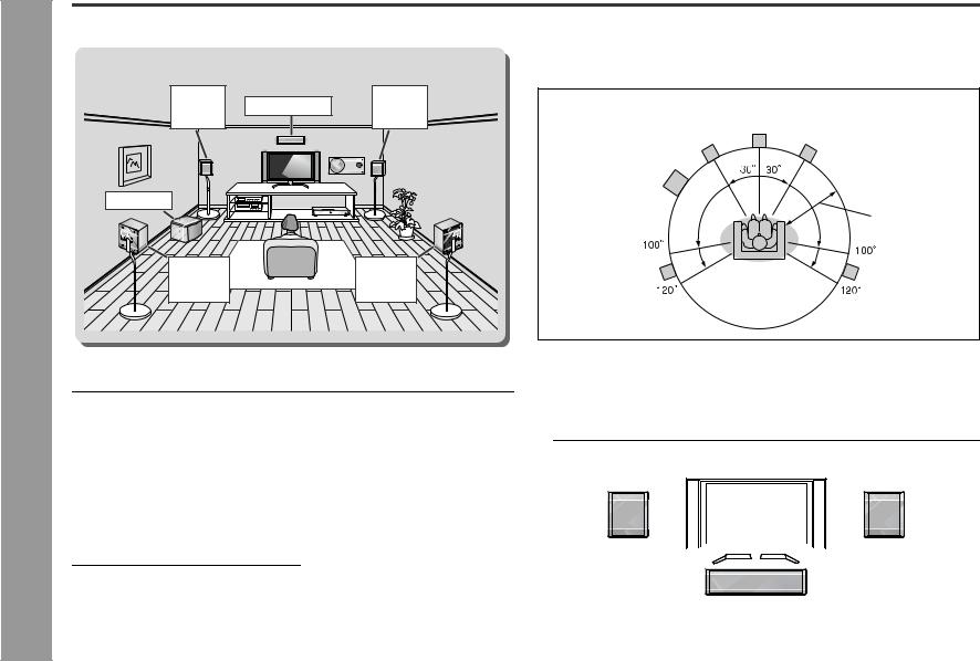
System installation
Installation image (with optional accessories):
Front |
Center speaker |
Front |
speaker |
speaker |
|
(left) |
|
(right) |
Subwoofer
Surround |
Surround |
speaker |
speaker |
(left) |
(right) |
" Magnetically shielded speakers
The front, surround and center speakers may be placed beside or near the TV as they are magnetically shielded. However, discoloration may occur depending on the TV type.
If color variation occurs...
Turn off the TV (with the power switch).
After 15 - 30 minutes, turn the TV on again.
If the color variation is still present...
Move the speakers further away from the TV.
Refer to the manual of the TV for details.
Note:
The subwoofer is not magnetically shielded.
" Placing the speaker system
The best surround effect will be achieved by placing each speaker at the same distance from the listening position.
It is recommended to arrange the speakers as shown below.
Front |
Center |
|
speaker Front |
||
speaker (left) |
speaker (right) |
|
Subwoofer |
|
|
|
Default setting: |
|
|
6 feet (2 m) |
|
Surround |
Surround |
|
speaker (left) |
||
speaker (right) |
||
|
Notes:
!The default distance is set to 6 feet (2 m). If speakers cannot be placed at equal distances, refer to "Speaker delay setting" (see page 44).
!Place the TV halfway between the front speakers.
!It is recommended that the center speaker be placed near the television.
!Place the surround speakers at a position just above the height of your ears.
!You can place the subwoofer anywhere you like. As it vibrates while reproducing bass, place it on a stable, sturdy surface.
Front speaker (left)  Front speaker (right)
Center speaker
14

Main unit preparation
SD-AS10
Select from three installation methods according to the location.
For position A or B, make sure to use the included main unit stand. Otherwise the unit may fall.
The display direction changes according to the installation direction.
Position A |
Position B |
Position C |
L |
R |
L |
R |
|
SW |
|
SW |

 L
L 


 R
R 


 SW
SW

1 Remove the 2 screws.
2 Secure the stand with the removed screws.
Main unit stand
YES
Correct
1 Remove the 2 screws.
Make all connections  before attaching the stand (see pages 17, 19).
2 Secure the stand with the removed screws.
Main unit stand
NO
1Align the position with the remote sensor and attach the included button name label.
Button name label
Remote sensor
2 Fit the non-slip sheets into the groove.
Non-slip sheet |
for main unit |
YES |
NO |
Correct |
|
Notes:
!When attaching the stand, place the main unit on a cushion or soft cloth to avoid damage.
!Use the removed screw to secure the stand. Otherwise, the unit may break.
Caution:
!Do not change the installation direction when the main unit is turned on. Discs may not be read or may be damaged.
!Remove the only specified screws. Malfunction may occur. Be careful not to lose the removed screws.
!To turn on the power after the first installation or after changing the installation method, use the POWER button on the main unit. From the next time, you can also use the remote control.
Preparation for Use - Main unit preparation -
15

SD-AS10 System connections
Preparation for Use - System connections -
Make sure to unplug the AC power cord before making any connections.
TV connection (see page 19)
Connect a TV and main unit with the included video cable. If your TV is equipped with an S-video input jack or component video input jacks, purchase an appropriate cable to enjoy higher quality images.
TV
Antenna connection (see page 17)
 FM antenna AM loop antenna
Attaching the side cover (see page 19)
You can position cables differently by changing installation.
Main unit
Connecting the system connection cable (see page 17)
Amplifier unit
AC power connection
(see page 20)
Front speaker |
Center speaker |
Front speaker |
|
(left) |
(right) |
||
|
|
|
|
|
|
|
|
|
|
|
|
|
|
|
|
|
|
|
|
|
|
|
|
|
Surround speaker |
|
|
|
|
|
Surround speaker |
|||||
Subwoofer |
|||||||||||
|
(left) |
|
(right) |
||||||||
|
|
|
|
|
|
|
|||||
Speaker connection (see page 18)
16

" Connecting the system connection cable
Connect the main unit and amplifier unit as follows.
Amplifier unit
To connect:
The plug is directional. Connect it with the arrow facing toward the screw.
To disconnect:
Pull the plug straight out pressing the plug.
System connection cable
Screw
Arrow
1 Push
2 Unplug
Main unit
How to open side cover
Open the side cover to connect the system.
2 1
Antenna connection
Supplied FM antenna:
Connect the FM antenna wire to the FM 75 OHMS jack and position the FM antenna wire in the direction where the strongest signal can be received.
Supplied AM loop antenna:
Connect the AM loop antenna wire to the AM and GND terminals. Position the AM loop antenna for optimum reception. Place the AM loop antenna on a shelf, etc., or attach it to a stand or a wall with screws (not supplied).
Note:
Placing the antenna on the unit or near the AC power cord may cause noise pickup. Place the antenna away from the unit for better reception.
FM antenna AM loop antenna
Black 
 White
White
Amplifier unit
Installing the AM loop antenna:
< Assembling > < Attaching to the wall >
|
|
|
Wall |
Screws (not supplied) |
|
Outdoor FM or AM antenna:
Use an outdoor FM or AM antenna if you require better reception. Consult your dealer.
When using an outdoor AM antenna, be sure to keep the wire of the AM loop antenna connected.
Outdoor FM antenna
Outdoor AM antenna 49 feet (15 m)
25 feet (7.5 m)
Ground rod |
Ground wire |
AM loop antenna
SD-AS10
Preparation for Use - System connections / Antenna connection -
17
SD-AS10
Preparation for Use - Speaker connection -
18
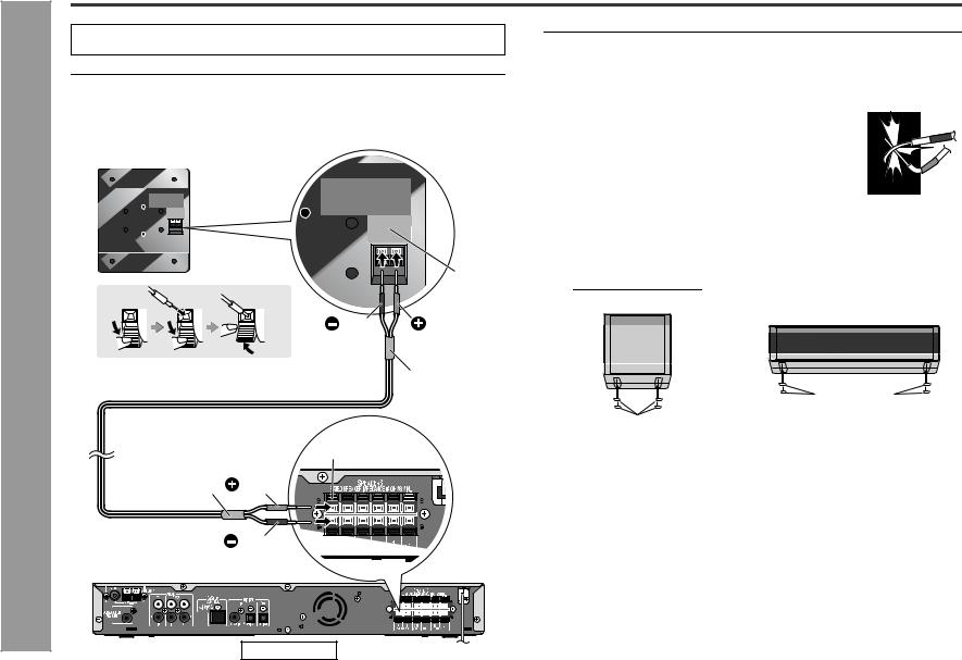
Speaker connection
Make sure to leave the AC power cord disconnected when connecting the speakers.
To prevent accidental short circuits between  and
and  terminals, connect the
speaker wires to the speakers first and then to the unit.
Connect the speaker and the unit by matching the colors.
1 Connect the wires to the speakers.
Example :To connect the right surround speaker.
Label (gray)
Black |
Red |
|
Tube (gray) |
2 Connect the other end to the amplifier unit.
Speaker terminal (gray)
Tube (gray) |
Red |
|
Black |
Caution:
!The supplied speakers are designed exclusively for SD-AS10. Do not connect these speakers to other equipment. Also, do not connect other speakers to SD-AS10. It may cause malfunction.
!Do not mistake the  and
and  , and right and left terminals of the speaker wires. (The right speaker is placed on the right when you face the unit.)
!Do not let the bare speaker wires touch each other.
!Do not stand or sit on the speakers. You may be injured.
! Do not short-circuit the speaker wire. If it happens with the |
|
power on, the protection circuit is activated and the unit is |
|
set to the power stand-by mode. In this case, check that the |
|
speaker wire is connected correctly before turning on the |
|
power again. |
|
! The speakers grilles are not removable. |
Incorrect |
! Do not allow any objects to fall into or to be placed in the bass |
|
reflex ducts. |
|
Non-slip sheet for speakers:
Attach the sheets to the bottom of the speaker to prevent it from sliding.
Front/Surround speakers |
Center speaker |
||
|
|
|
|
|
|
|
|
|
|
|
|
|
|
|
|
Non-slip sheet for speakers
Non-slip sheet for speakers
Amplifier unit
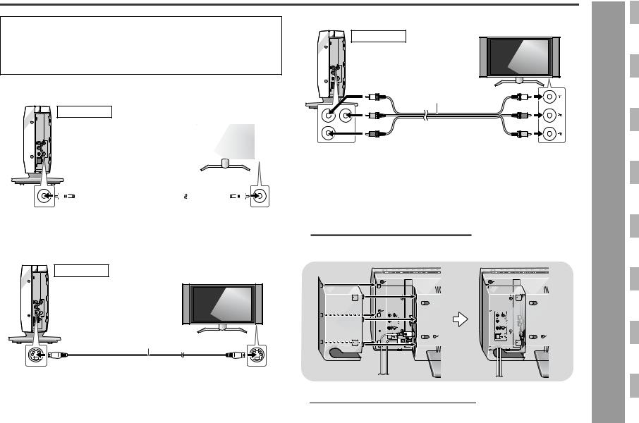
TV connection
Three types of jacks (VIDEO OUT, S-VIDEO OUT and COMPONENT VIDEO OUT) are available for connection of a TV and this unit. Connect according to your TV.
Connect the optional S-video cable or component video cable for higher quality DVD images. For the component video cable, the progressive video mode is available and you can enjoy images with less flicker (default setting: PROGRESSIVE OFF). See page 25 for details.
Connecting to a TV with a video input jack
Main unit |
TV |
|
|
|
|
|
|
|
|
|
|
|
|
|
|
|
|
|
|
|
|
|
|
|
|
|
|
|
|
|
|
|
|
|
|
|
|
|
|
|
|
|
|
|
|
|
|
|
|
|
|
|
|
|
|
|
|
|
|
|
|
|
|
|
|
|
|
|
|
|
|
|
|
|
|
|
|
|
|
|
|
|
|
|
|
|
|
|
|
|
|
To video |
To video |
||||||||||
|
|
|
|
|
||||||||||||
|
|
|
|
|
output jack Video cable (supplied) |
input jack |
||||||||||
|
|
|
|
|
|
|
|
|
|
|
|
|
|
|
|
|
|
|
|
|
|
|
|
|
|
|
|
|
|
|
|
|
|
Connecting to a TV with an S-video input jack
Main unit
TV
Connecting to a TV with component video input jacks
Main unit |
TV |
|
|
To component |
|
video output jacks |
|
Green |
Component video cable |
Green |
Red |
(commercially available) |
Blue |
|
||
Blue |
To component |
Red |
|
|
|
|
video input jacks |
|
Notes:
!Change the TV input in accordance with the connected jack.
!Do not connect other equipment between the TV and this unit. If they are connected via a VCR, pictures may be distorted.
!If your TV has different indications for the component video inputs (Y, CB and CR or Y, B-Y and P-Y), connect jacks with its matching color.
!Do not connect to a component video input jack designed for the high-vision system, which is not DVD-compatible (the images may be distorted or not appear).
!Using the audio cable, you can listen to the TV sound with this unit (see page 56).
" Attaching the side cover
S-video cable
To S-video (commercially available) output jack
To S-video input jack
1After making all the connections, attach the side cover to the main unit. Fit the claws into the holes.
2Route all the cables through the hole of the cover.
SD-AS10
Preparation for Use - TV connection -
19
SD-AS10
Preparation for Use - AC power connection / Remote control -
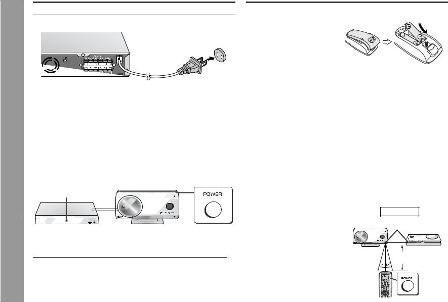
AC power connection
" Connecting the AC power cord
After checking all the connections have been made correctly, plug in the amplifier unit.
AC outlet
(AC 120 V, 60 Hz)
Note:
Unplug the AC power cord from the AC outlet if the unit will not be in use for a prolonged period of time.
" To turn the power on
Press the POWER button.
The power indicator on the amplifier unit lights up.
If the power does not turn on, check if the power cord and system connection cable are plugged in properly.
To set the unit to stand-by mode:
Press the POWER button again.
Note:
After the unit enters the power stand-by mode, wait a few seconds to turn on again.
Power indicator
Amplifier unit |
|
Main unit |
" Auto power off function
The unit enters the stand-by mode after 20 minutes of inactivity in DVD operation.
Remote control
" Battery installation
1 Open the battery cover.
2 Insert the supplied batteries according to the direction indicated in the battery compartment.
When inserting or removing the batteries, push them toward the  battery terminals.
3 Close the cover.
Precautions for battery use:
!Replace all old batteries with new ones at the same time.
!Do not mix old and new batteries.
!Remove the batteries if the unit will not be used for long periods of time. This will prevent potential damage due to battery leakage.
Caution:
!Do not use rechargeable batteries (nickel-cadmium battery, etc.).
!Installing the batteries incorrectly may cause the unit to malfunction.
Notes concerning use:
!Replace the batteries if the operating distance is reduced or if the operation becomes erratic. Purchase 2 "AA" size batteries (UM/SUM-3, R6, HP-7 or similar).
!Periodically clean the transmitter on the remote control and the sensor on the unit with a soft cloth.
!Exposing the sensor on the unit to strong light may interfere with operation. Change the lighting or the direction of the unit.
!Keep the remote control away from moisture, heat, shock, and vibrations.
" Test of the remote control
Point the remote control directly at the remote sensor on the unit.
The remote control can be used within the range shown on the right.
Press the POWER button. Does the power turn on? Now, you can enjoy your system.
! Use 2 remote sensors on the main unit according to the installation method.
Main unit
Remote
sensor
8" - 20' (0.2 m - 6 m)
20
 Loading...