


LC-60LE650U
No. S13A6LC60LE65
SAFETY PRECAUTION
OUTLINE
CHAPTER 1. SPECIFICAT IONS
CHAPTER 2. OPERATION MANUAL
CHAPTER 3. DIMENSIONS
CHAPTER 4. REMOVING OF MAJOR PARTS
CHAPTER 5. ADJUSTMENT
CHAPTER 6. TROUBLESHOOTING TABLE
CHAPTER 7. MAJOR IC INFORMATIONS
CHAPTER 8. OVERALL WIRING/SYSTEM BLOCK
DIAGRAM
Parts Guide
XXXXXXX
SERVICE MANUAL
LC-60/70LE650U/C6500U/LE657U,LC-60/70LE755U/LE757U/LE857U/C7500U
(1st Edition)
Parts marked with " " are important for maintaining the safety of the set. Be sure to replace these parts with specified ones for maintaining the
safety and performance of the set.
This document has been published to be used for
after sales service only.
The contents are subject to change without notice.
TopPe
CONTENTS
In the interests of user-safety (Required by safety regulations in some countries) the se t should be restored to its orig-
inal condition and only parts identical to those specified should be used.
LC-60/70LE650U,LC-60/70C6500U
LC-60/70LE657U,LC-60/70LE755U
LC-60/70LE757U,LC-60/70LE857U
LC-60/70C7500U
MODELS

LC-60/70LE650U/C6500U/LE657U,LC-60/70LE755U/LE757U/LE857U/C7500U
CONTENTS
SAFETY PRECAUTION
IMPORTANT SERVICE SAFETY PRE-
CAUTION.........................................................i
PRECAUTIONS A PRENDRE LORS DE
LA REPARATION............................................ii
PRECAUTIONS FOR USING LEAD-
FREE SOLDER..............................................iii
OUTLINE
MAJOR SERVICE PARTS.............................iv
CHAPTER 1. SPECIFICA TIONS
[1] SPECIFICATIONS...................................... 1-1
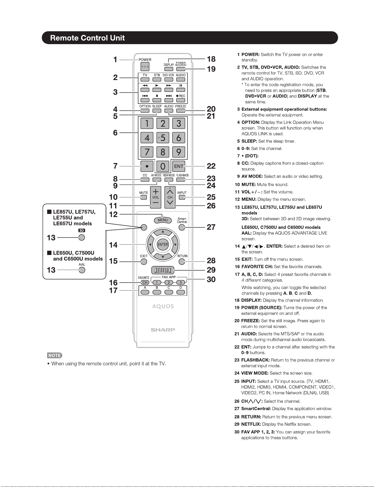
CHAPTER 2. OPERATION MANUAL
[1] OPERATION MANUAL............................... 2-1
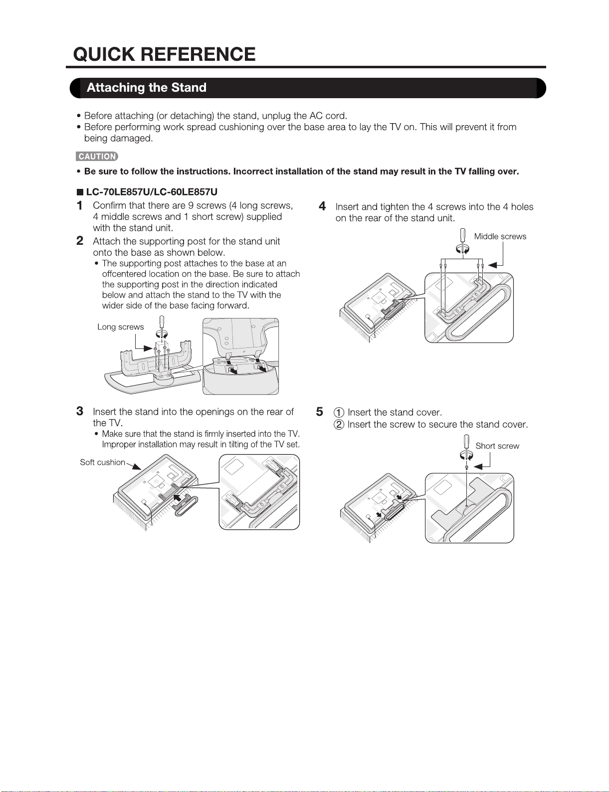
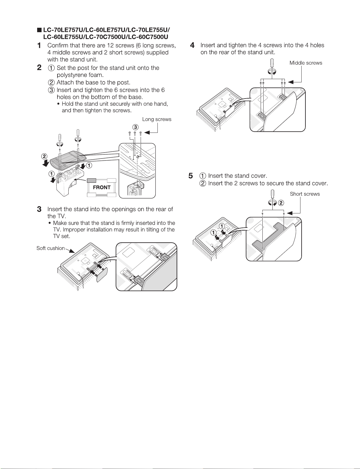
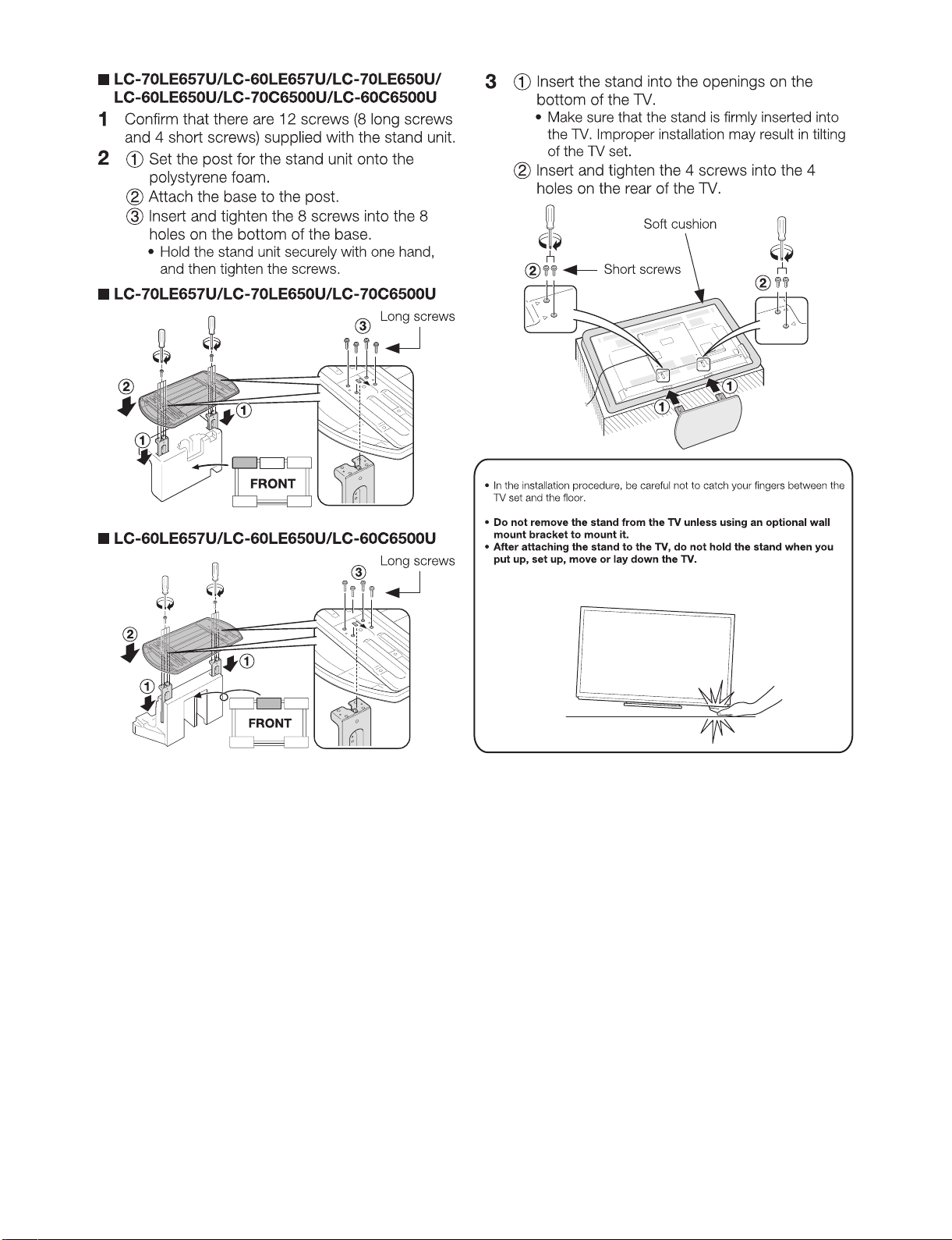
CHAPTER 3. DIMENSIONS
[1] DIMENSIONS ............................................. 3-1
CHAPTER 4. REMOVING OF MAJOR PARTS
[1] REMOVING OF MAJOR PARTS (LC-
60LE650U/C6500U/LE657U)...................... 4-1
[2] REMOVING OF MAJOR PARTS (LC-
70LE650U/C6500U/LE657U)...................... 4-7
[3] The location putting on the heat measur e
sheet (LC-60/70LE650U/C6500U/
LE657U)....................................................4-13
[4] Precautions for assembly (LC-60/
70LE650U/C6500U/LE657U).................... 4-14
[5] REMOVING OF MAJOR PARTS (LC-
60LE755U/757U/LE857U/C7500U).......... 4-17
[6] REMOVING OF MAJOR PARTS (LC-
70LE755U/757U/LE857U/C7500U).......... 4-22
[7] The location putting on the heat measur e
sheet (LC-60/70LE755U/757U/L E85 7U/
C7500U).................................................... 4-27
[8] Precautions for assembly (LC-60/
70LE755U/757U/LE857U/C7500U).......... 4-28
CHAPTER 5. ADJUSTMENT
[1] ADJUSTMENT PROCEDURE.................... 5-1
[2] PUBLIC MODE SETTING PROCE-
DURE........................................................ 5-15
CHAPTER 6. TROUBLESHOOTING TABLE
[1] Failure diagnosis by LED in front of cab-
inet.............................................................. 6-1
[2] LED flashing specification at the time of
an error (Center icon LED used)................. 6-1
[3] TROUBLESHOOTING TABLE (LC-60/
70LE650U/C6500U/LE657U)...................... 6-4
[4] TROUBLESHOOTING TABLE (LC-60/
70LE755U/757U/LE857U/C7500U).......... 6-22
CHAPTER 7. MAJOR IC INFORMATIONS
[1] MAJOR IC INFORMATIONS....................... 7-1
CHAPTER 8. OVERALL WIRING/SYSTEM BLOCK
DIAGRAM
[1] OVERALL WIRING DIAGRAM (LC-60/
70LE650U/C6500U).................................... 8-1
[2] OVERALL WIRING DIAGRAM (LC-60/
70LE657U)..................................................8-2
[3] OVERALL WIRING DIAGRAM (LC-
60LE755/757U/LE857U/C7500U)............... 8-3
[4] OVERALL WIRING DIAGRAM (LC-
70LE755/757U/LE857U/C7500U)............... 8-4
[5] SYSTEM BLOCK DIAGRAM (LC-60/
70LE650U/C6500U/7500U).... .................... 8-5
[6] SYSTEM BLOCK DIAGRAM (LC-60/
70LE657U/LE755U/757U/LE857U)............ 8-6
Parts Guide
LC-60/70LE650U/C6500U/LE657U,LC-60/70LE755U/LE757U/LE857U/C7500U
i
LC-60LE650U
Service Manual
SAFETY PRECAUTION
IMPORTANT SERVICE SAFETY PRECAUTION
WARNING
1. For continued safety, no modification of any circuit should be
attempted.
2. Disconnect AC power before servicing.
BEFORE RETURNING THE RECEIVER (Fire &
Shock Hazard)
Before returning the receiver to the user, perform the following
safety checks:
3. Inspect all lead dress to make certain that leads are not pinched,
and check that hardware is not lodged between the chassis and
other metal parts in the receiver.
4. Inspect all protective devices such as non-metallic control knobs,
insulation materials, cabinet backs, adjustment and compartment
covers or shields, isolation resistor-capacitor networks, mechanical
insulators, etc.
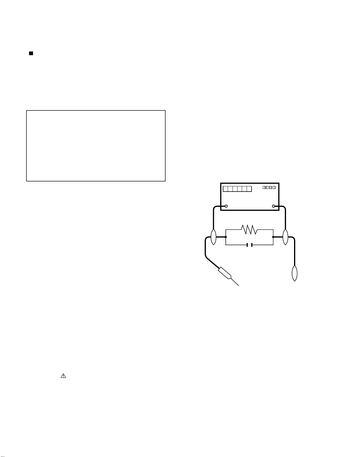
5. To be sure that no shock hazard exists, check for leakage current
in the following manner.
• Plug the AC cord directly into a 120 volt AC outlet.
• Using two clip leads, connect a 1.5k ohm, 10 watt resistor paral-
leled by a 0.15µF capacitor in series with all exposed metal cabinet
parts and a known earth ground, such as electrical conduit or elec-
trical ground connected to an earth ground.
• Use an AC voltmeter having with 5000 ohm per volt, or higher, sen-
sitivity or measure the AC voltage drop across the resistor.
• Connect the resistor connection to all exposed metal parts having a
return to the chassis (antenna, metal cabinet, screw heads, knobs
and control shafts, escutcheon, etc.) and measure the AC voltage
drop across the resistor.
All checks must be repeated with the AC cord plug connection
reversed. (If necessary, a nonpolarized adaptor plug must be used
only for the purpose of completing these checks.)
Any reading of 0.75 Vrms (this corresponds to 0.5 mA rms AC.) or
more is excessive and indicates a potential shock hazard which
must be corrected before returning the monitor to the owner.
///////////////////////////////////////////////////////////////////////////////////////////////////////////////////////////////////////////////////////////////////////////////////////////////////////////////////////////////////////////
SAFETY NOTICE
Many electrical and mechanical parts in LCD color television have
special safety-related characteristics.
These characteristics are often not evident from visual inspection, nor
can protection afforded by them be necessarily increased by using
replacement components rated for higher voltage, wattage, etc.
Replacement parts which have these special safety characteristics are
identified in this manual; electrical components having such features
are identified by " " and shaded areas in the Replacement Parts List
and Schematic Diagrams.
For continued protection, replacement parts must be identical to those
used in the original circuit.
The use of a substitute replacement parts which do not have the same
safety characteristics as the factory recommended replacement parts
shown in this service manual, may create shock, fire or other hazards.
///////////////////////////////////////////////////////////////////////////////////////////////////////////////////////////////////////////////////////////////////////////////////////////////////////////////////////////////////////////
Service work should be performed only by qualified service technicians who are thoroughly familiar with all safety checks and the
servicing guidelines which follow:
CAUTION: FO R C O N T I N U E D PROTECTION
AGAINST A RISK OF FIRE REPLACE ONLY WITH
SAME TYPE FUSE.
F7001 (250V 5A)
DVM
AC SCALE
1.5k ohm
10W
TO EXPOSED
METAL PARTS
CONNECT TO
KNOWN EARTH
GROUND
0.15
µ
F
TEST PROBE
LC-60/70LE650U/C6500U/LE657U,LC-60/70LE755U/LE757U/LE857U/C7500U
ii
PRECAUTIONS A PRENDRE LORS DE LA REPARATION
De nombreuses pièces, électriques et mécaniques, dans les télévi-
seur ACL présentent des caractéristiques spéciales relatives à la sé-
curité, qui ne sont souvent pas évidentes à vue. Le degré de protec-
tion ne peut pas être nécessairement augmentée en utilisant des
pièces de remplacement étalonnées pour haute tension, puissance,
etc.
Les pièces de remplacement qui présentent ces caractéristiques sont
identifiées dans ce manuel; les pièces électriques qui présentent ces
particularités sont identifiées par la marque " " et hachurées dans la
liste des pièces de remplacement et les diagrammes schématiques.
Pour assurer la protection, ces pièces doivent être identiques à celles
utilisées dans le circuit d'origine. L'utilisation de pièces qui n'ont pas
les mêmes caractéristiques que les pièces recommandées par l'usine,
indiquées dans ce manuel, peut provoquer des électrocutions, incen-
dies, radiations X ou autres accidents.
AVERTISSEMENT
1.
2.
3.
4.
5.
•
•
•
•
/////////////////////////////////////////////////////////////////////////////////////////////////////////////////////////////////////////////////////////////////////////////////////////////////////////////////////////////////////////////
/////////////////////////////////////////////////////////////////////////////////////////////////////////////////////////////////////////////////////////////////////////////////////////////////////////////////////////////////////////////
Ne peut effectuer la réparation qu' un technicien spécialisé qui s'est parfaitement accoutumé à toute vérification de sécurité et aux
conseils suivants.
N'entreprendre aucune modification de tout circuit. C'est danger-
eux.
Débrancher le récepteur avant toute réparation.
Inspecter tous les faisceaux de câbles pour s'assurer que les fils
ne soient pas pincés ou qu'un outil ne soit pas placé entre le châs-
sis et les autres pièces métalliques du récepteur.
Inspecter tous les dispositifs de protection comme les boutons de
commande non-métalliques, les isolants, le dos du coffret, les cou-
vercles ou blindages de réglage et de compartiment, les réseaux
de résistancecapacité, les isolateurs mécaniques, etc.
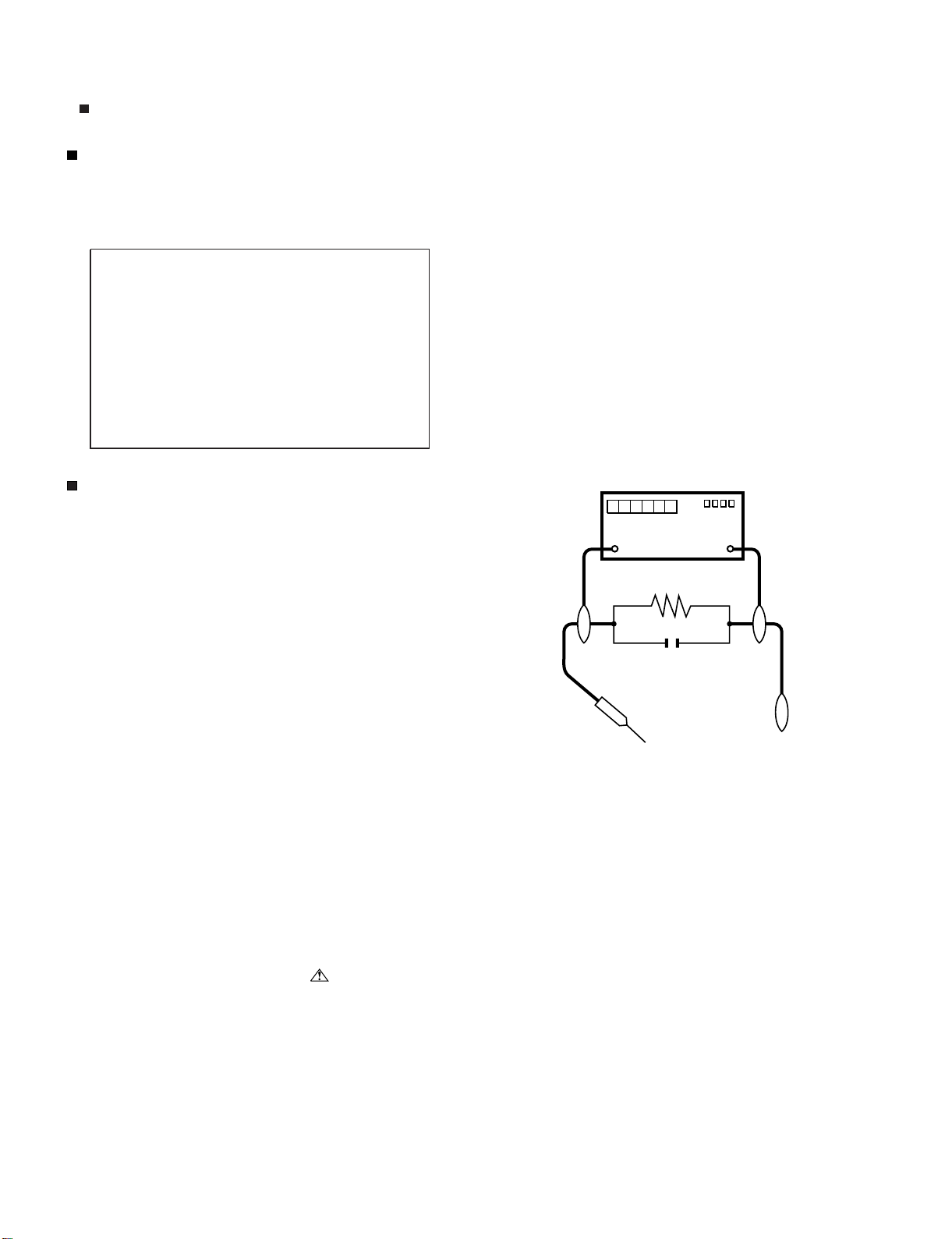
S'assurer qu'il n'y ait pas de danger d'électrocution en vérifiant la
fuite de courant, de la facon suivante:
Brancher le cordon d'alimentation directem-ent à une prise de cou-
rant de 120V. (Ne pas utiliser de transformateur d'isolation pour
cet essai).
A l'aide de deux fils à pinces, brancher une résistance de 1.5 kΩ
10 watts en parallèle avec un condensateur de 0.15µF en série
avec toutes les pièces métalliques exposées du coffret et une terre
connue comme une conduite électrique ou une prise de terre
branchée à la terre.
Utiliser un voltmètre CA d'une sensibilité d'au moins 5000Ω/V pour
mesurer la chute de tension en travers de la résistance.
Toucher avec la sonde d'essai les pièces métalliques exposées qui
présentent une voie de retour au châssis (antenne, coffret métalli-
que, tête des vis, arbres de commande et des boutons, écusson,
etc.) et mesurer la chute de tension CA en-travers de la résistance.
Toutes les vérifications doivent être refaites après avoir inversé la
fiche du cordon d'alimentation. (Si nécessaire, une prise
d'adpatation non polarisée peut être utilisée dans le but de termin-
er ces vérifications.)
La tension de pointe mesurèe ne doit pas dépasser 0.75V (corre-
spondante au courant CA de pointe de 0.5mA).
Dans le cas contraire, il y a une possibilité de choc électrique qui
doit être supprimée avant de rendre le récepteur au client.
PRECAUTION: POUR LA PROTECTION CON-
TINUE CONTRE LES RISQUES D'INCENDIE,
REMPLACER LE FUSIBLE
VERIFICATIONS CONTRE L'INCEN-DIE ET LE
CHOC ELECTRIQUE
Avant de rendre le récepteur à l'utilisateur, effectuer les vérifica-
tions suivantes.
DVM
ECHELLE CA
1.5k ohm
10W
0.15
µ
F
SONDE D'ESSAI
AUX PIECES
METALLIQUES
EXPOSEES
BRANCHER A UNE
TERRE CONNUE
AVIS POUR LA SECURITE
F7001 (250V 5A)
LC-60/70LE650U/C6500U/LE657U,LC-60/70LE755U/LE757U/LE857U/C7500U
iii
PRECAUTIONS FOR USING LEAD-FREE SOLDER
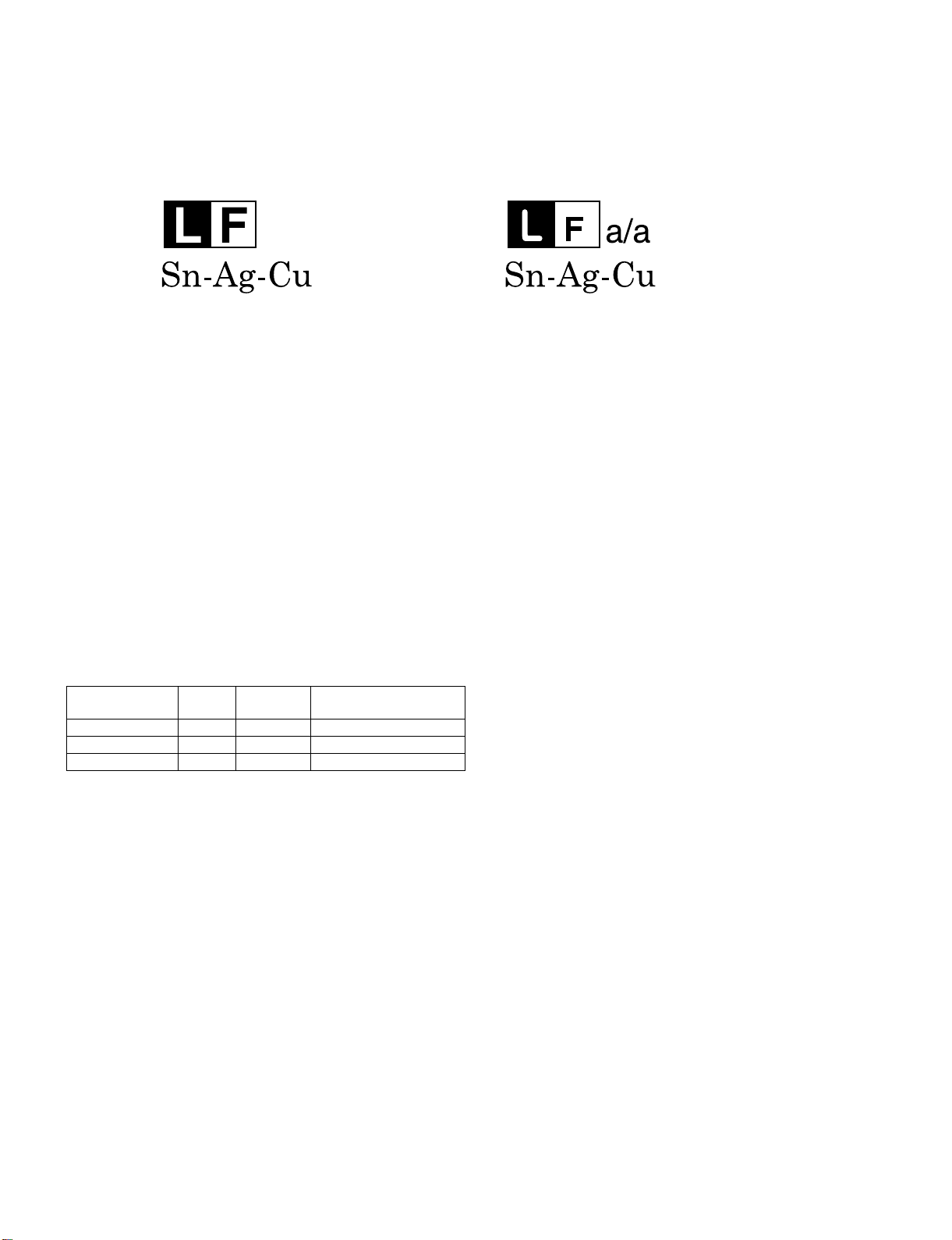
Employing lead-free solder
• “PWBs” of this model employs lead-free solder. The LF symbol indicates lead-free solder, and is attached on the PWBs and service manuals. The
alphabetical character following LF shows the type of lead-free solder.
Example:
Using lead-free wire solder
• When fixing the PWB soldered with the lead-free solder, apply lead-free wire solder. Repairing with conventional lead wire solder may cause dam-
age or accident due to cracks.
As the melting point of lead-free solder (Sn-Ag-Cu) is higher than the lead wire solder by 40 °C, we recommend you to use a dedicated soldering
bit, if you are not familiar with how to obtain lead-free wire solder or soldering bit, contact our service station or service branch in your area.
Soldering
• As the melting point of lead-free solder (Sn-Ag-Cu) is about 220 °C which is higher than the conventional lead solder by 40 °C, and as it has poor
solder wettability, you may be apt to keep the soldering bit in contact with the PWB for extended period of time. However, Since the land may be
peeled off or the maximum heat-resistance temperature of parts may be exceeded, remove the bit from the PWB as soon as you confirm the
steady soldering condition.
Lead-free solder contains more tin, and the end of the soldering bit may be easily corroded. Make sure to turn on and off the power of the bit as
required.
If a different type of solder stays on the tip of the soldering bit, it is alloyed with lead-free solder. Clean the bit after every use of it.
When the tip of the soldering bit is blackened during use, file it with steel wool or fine sandpaper.
• Be careful when replacing parts with polarity indication on the PWB silk.
Lead-free wire solder for servicing
Indicates lead-free solder of tin, silver and copper. Indicates lead-free solder of tin, silver and copper.
PARTS CODE
PRICE
RANK
PART
DELIVERY
DESCRIPTION
ZHNDAi123250E BL J φ0.3mm 250g (1roll)
ZHNDAi126500E BK J φ0.6mm 500g (1roll)
ZHNDAi12801KE BM J φ1.0mm 1kg (1roll)
LC-60/70LE650U/C6500U/LE657U,LC-60/70LE755U/LE757U/LE857U/C7500U
iv
LC-60LE650U
Service Manual
OUTLINE
MAJOR SERVICE PARTS
PWB Unit
NOTE: *1 Replace MAIN PWB Units (DKEYMF953FM06) in case of IC3103 and IC3104 failure.
*2 Replace LCD CONTROL Units (DUNTKF975FM20) in case of IC5803 failure.(LC-60/70LE650U/C6500U/LE657U)
OTHER Unit
IC For Exclusive Use Of The Service
Service Jigs
Ref NO. PARTS CODE DESCRIPTION
LC-60/70LE650U/C6500U/LE657U
N DKEYMF953FM06 MAIN Unit
N DUNTKF975FM20 LCD CONTROL Unit
N DUNTKF800FM53 KEY Unit
N DUNTKG014FM02 ICON Unit (LC-60/70LE657U)
N DUNTKG014FM03 ICON Unit (LC-60/70LE650U/C6500U)
N DUNTKG015FM03 R/C OPC Unit
N RUNTKA936WJQZ Wi-Fi Unit
N RUNTKB126WJQZ BLUETOOTH Unit (LC-60/70LE657U)
N RUNTKB109WJQZ POWER/LED DRIVER Unit (LC-60LE650U/C6500U/LE657U)
N RUNTKB131WJQZ POWER/LED DRIVER Unit (LC-70LE650U/C6500U/LE657U)
LC-60/70LE755U/757U/857U/C7500U
N DKEYMF953FM06 MAIN Unit
N DUNTKF961FM19 LCD CONTROL UNIT (LC-60LE755U/757U/857U/C7500U)
N DUNTKF961FM20 LCD CONTROL UNIT (LC-70LE755U/757U/857U/C7500U)
N DUNTKF800FM53 KEY Unit
N DUNTKG014FM02 ICON Unit (LC-60/70LE755U/757U/857U)
N DUNTKG014FM03 ICON Unit (LC-60/70C7500U)
N DUNTKG015FM03 R/C OPC Unit
N RUNTKB116WJQZ POWER/DRIVE Unit (LC-60LE755U/757U/857U/C7500U)
N RUNTKB118WJQZ POWER/DRIVE Unit (LC-70LE755U/757U/857U/C7500U)
N RUNTKA936WJQZ WiFi Unit
N RUNTKB126WJQZ BLUETOOTH Unit (LC-60/70LE755U/757U/857U)
Ref NO. PARTS CODE DESCRIPTION
N R1JE600D3GV2AZ 60" LCD PANEL MODULE Unit (JE600D3GV2AZ) (LC-60LE650U/C6500U/LE657U)
N R1JE695D3GW8CD 70" LCD PANEL MODULE Unit (JE695D3GW8CD) (LC-70LE650U/C6500U/LE657U)
N R1JE600D3HD60Z 60" LCD PANEL HIRAKI (Open Cell) Unit (LC-60LE755U/757U/857U)
N R1JE695D3HB10Z 70" LCD PANEL HIRAKI (Open Cell) Unit (LC-70LE755U/757U/857U)
Ref No. Parts No. Description Q’ty
IC2004 RH-iXD515WJN7Q IC (Monitor Microprocessor) 1
Ref No. PARTS CODE DESCRIPTION Q'ty
N QCNW-C222WJQZ Connecting Cord L=1000mm 80pins, LCD Control Unit to LCD Panel Unit, x2 2
N QCNW-L214WJQZ
Connecting Cord L=1000mm 64pins, LCD Control Unit to LCD Panel Unit, x2 (LC-60/70LE755U/
757U/857U)
2
N QCNW-F676WJQZ Connecting Cord L=1000mm 41pins, Main to LCD Control Unit (LW) 1
N QCNW-M539WJQZ Connecting Cord L=1000mm 24-24/4pins, Power-Main/LCD Control (PD) 1
LC-60/70LE650U/C6500U/LE657U,LC-60/70LE755U/LE757U/LE857U/C7500U
1 – 1
LC-60LE650U
Service Manual
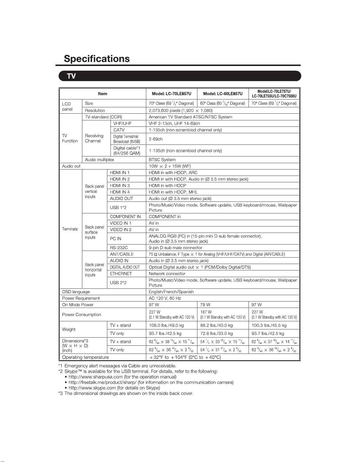
CHAPTER 1. SPECIFICATIONS
[1] SPECIFICATIONS
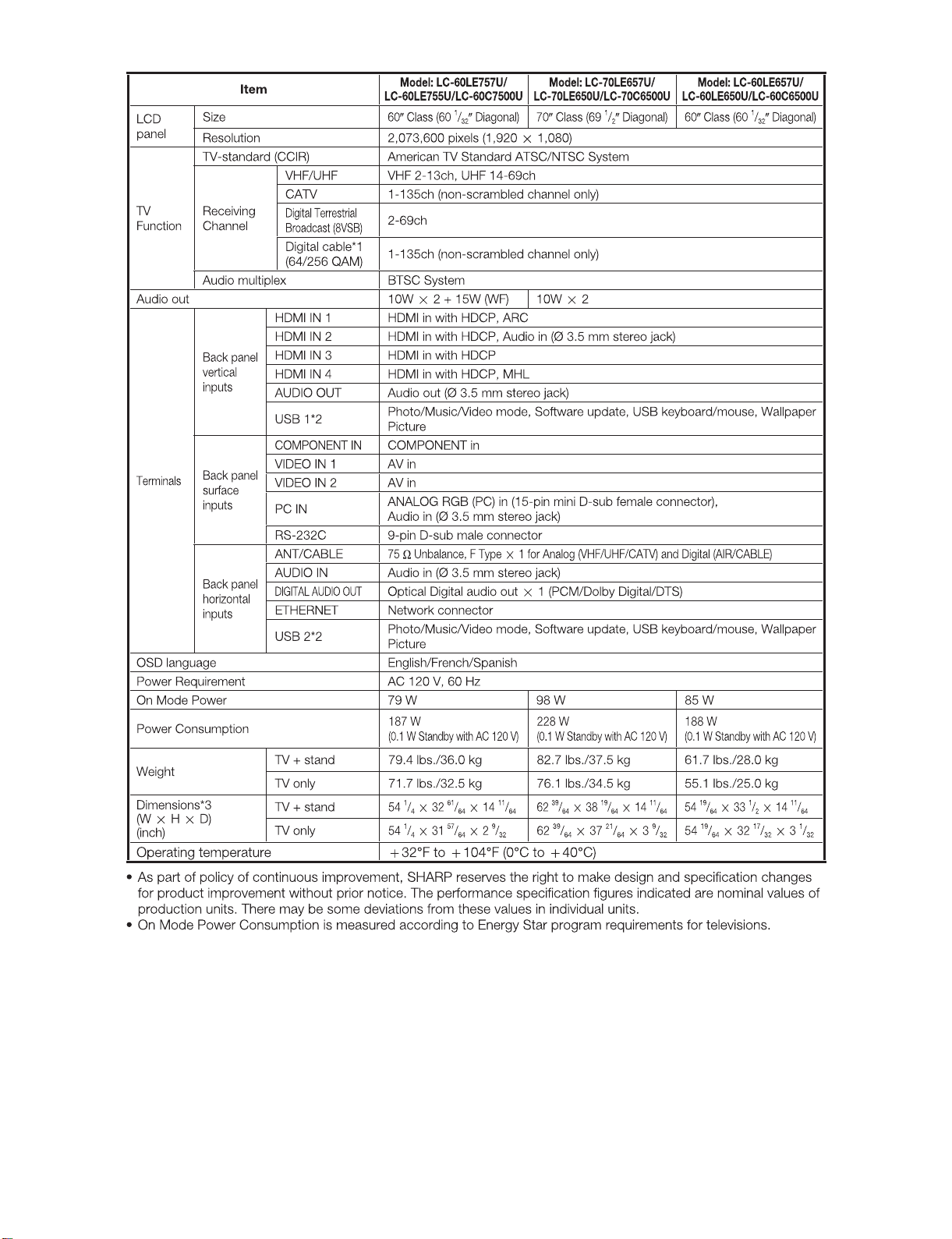
LC-60/70LE650U/C6500U/LE657U,LC-60/70LE755U/LE757U/LE857U/C7500U
1 – 2
LC-60/70LE650U/C6500U/LE657U,LC-60/70LE755U/LE757U/LE857U/C7500U
2 – 1
LC-60LE650U
Service Manual
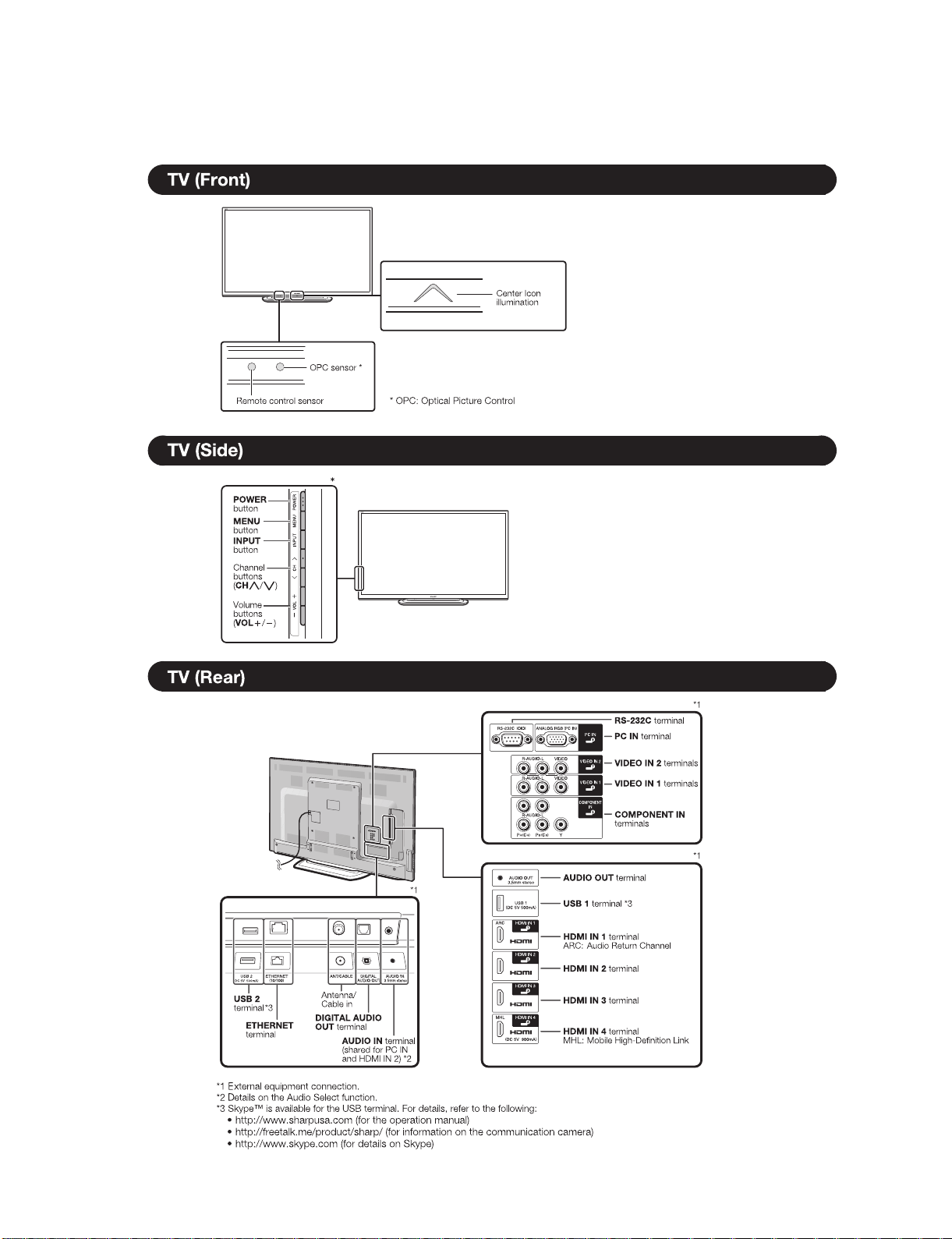
CHAPTER 2. OPERATION MANUAL
[1] OPERATION MANUAL
The examples used throughout this chapter are based on the LC-60LE650U model.
LC-60/70LE650U/C6500U/LE657U,LC-60/70LE755U/LE757U/LE857U/C7500U
2 – 2
LC-60/70LE650U/C6500U/LE657U,LC-60/70LE755U/LE757U/LE857U/C7500U
2 – 3
LC-60/70LE650U/C6500U/LE657U,LC-60/70LE755U/LE757U/LE857U/C7500U
2 – 4
LC-60/70LE650U/C6500U/LE657U,LC-60/70LE755U/LE757U/LE857U/C7500U
2 – 5
LC-60/70LE650U/C6500U/LE657U,LC-60/70LE755U/LE757U/LE857U/C7500U
3 – 1
LC-60LE650U
Service Manual
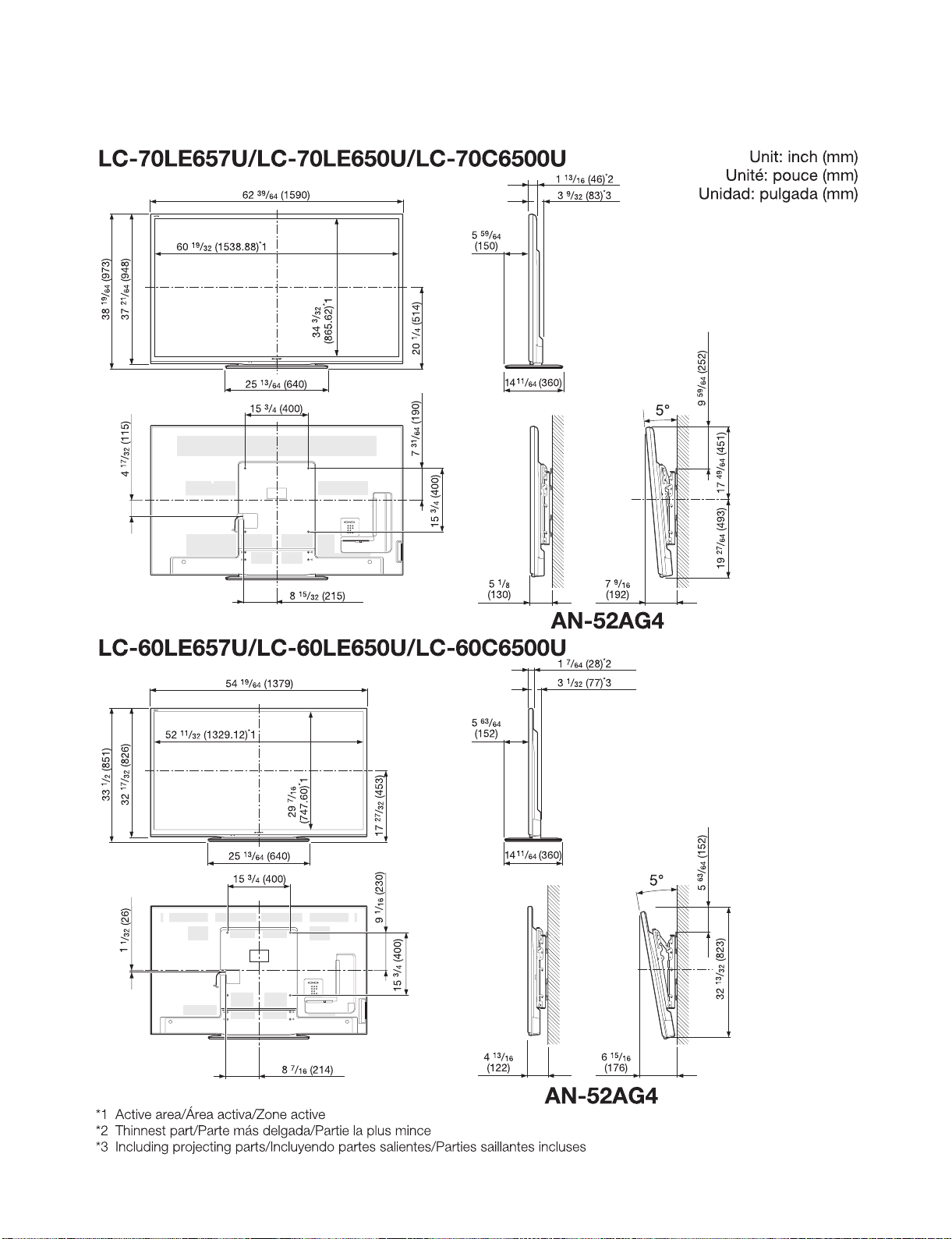
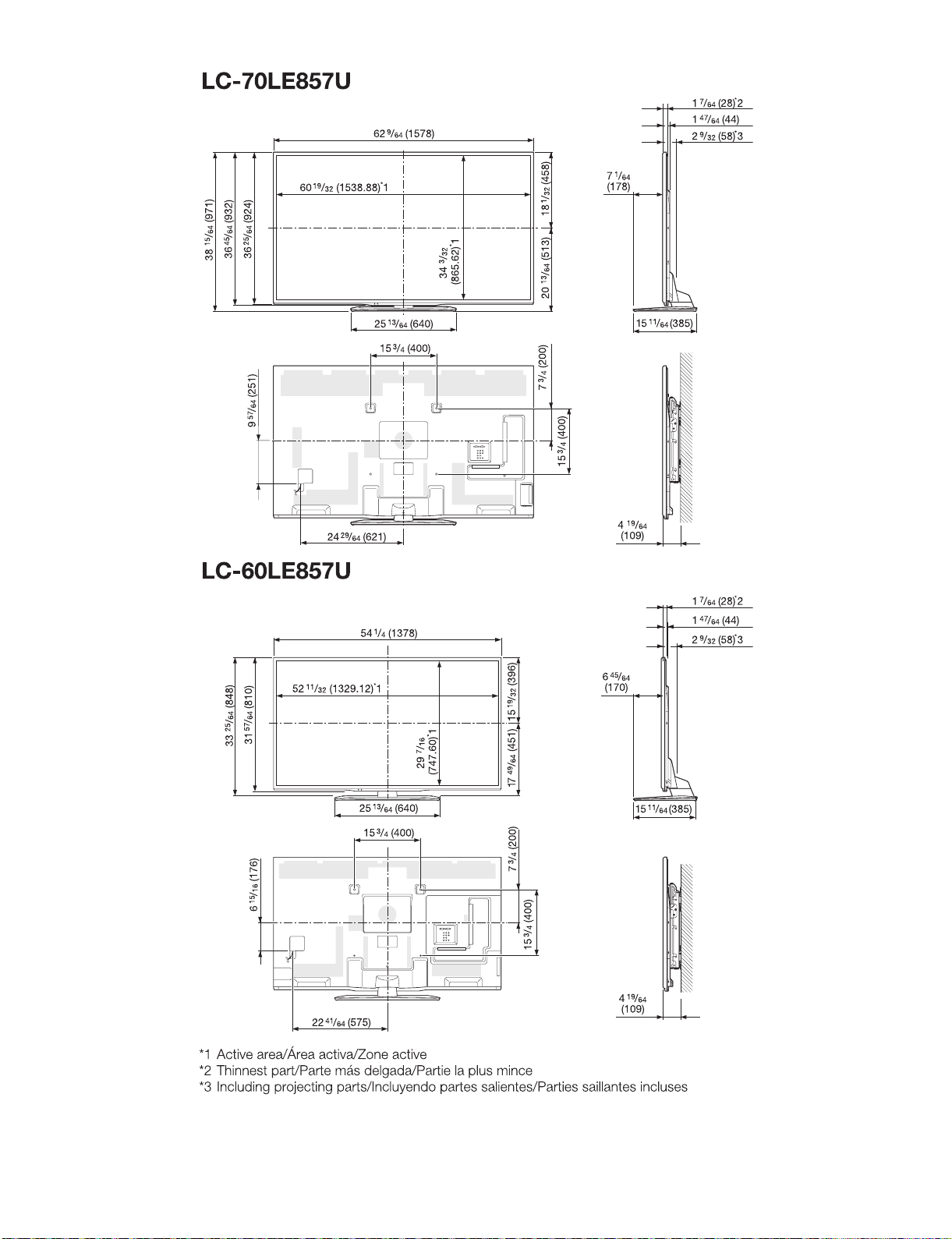
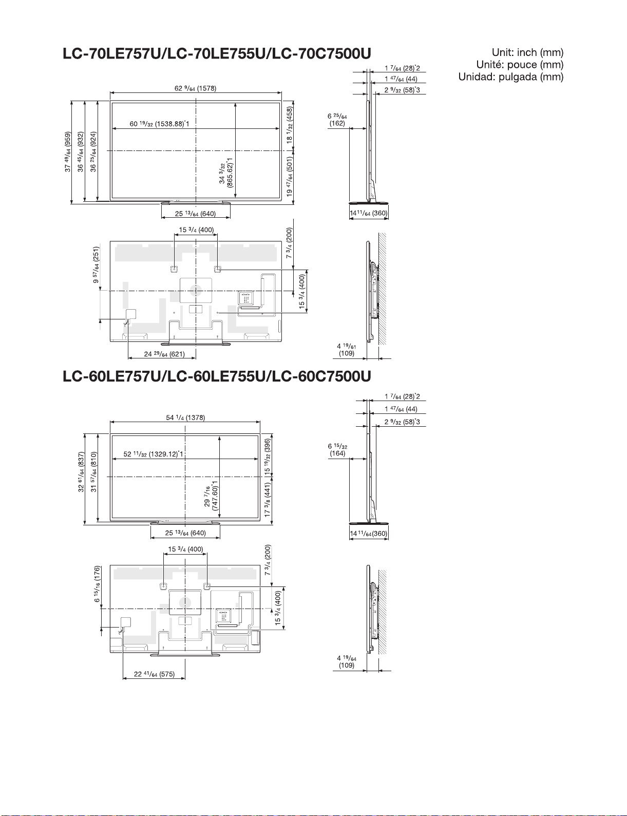
CHAPTER 3. DIMENSIONS
[1] DIMENSIONS
LC-60/70LE650U/C6500U/LE657U,LC-60/70LE755U/LE757U/LE857U/C7500U
3 – 2
LC-60/70LE650U/C6500U/LE657U,LC-60/70LE755U/LE757U/LE857U/C7500U
3 – 3
LC-60/70LE650U/C6500U/LE657U,LC-60/70LE755U/LE757U/LE857U/C7500U
4 – 1
LC-60LE650U
Service Manual
CHAPTER 4. REMOVING OF MAJOR PARTS
[1] REMOVING OF MAJOR PARTS (LC-60LE650U/C6500U/LE657U)
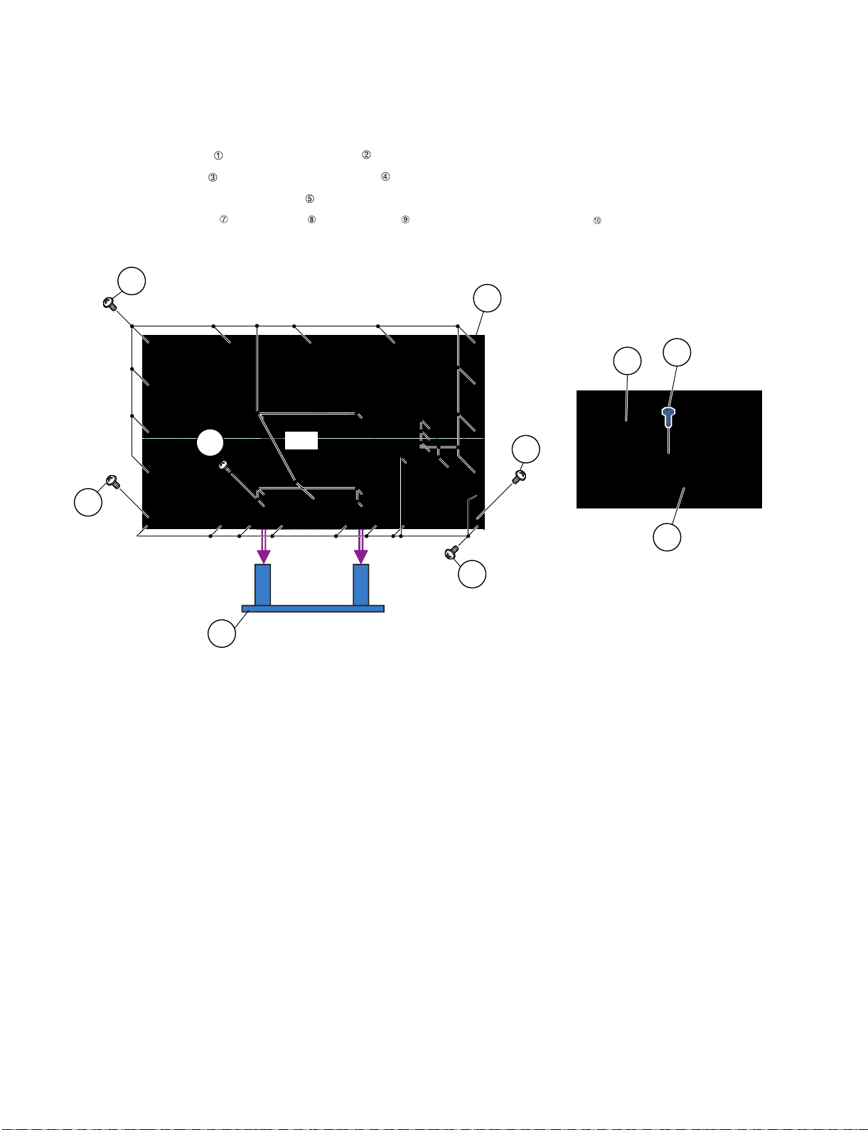
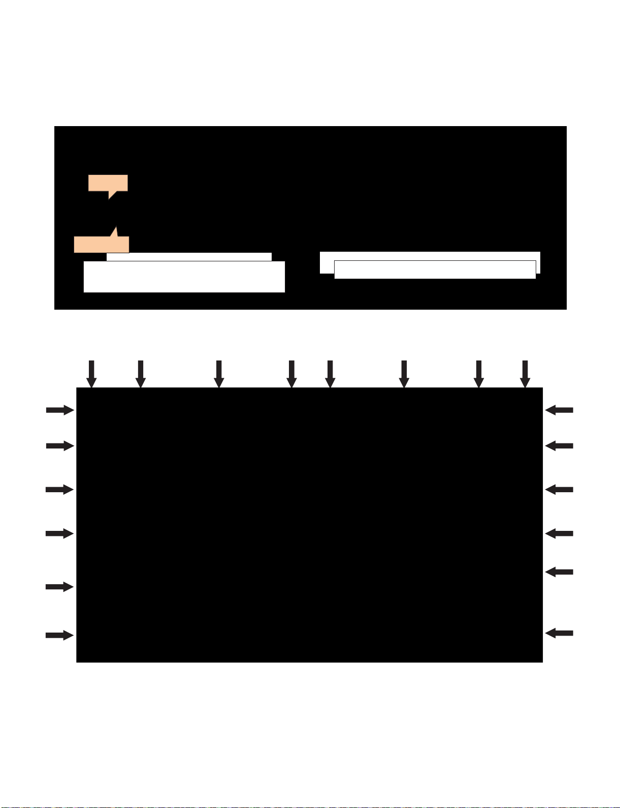
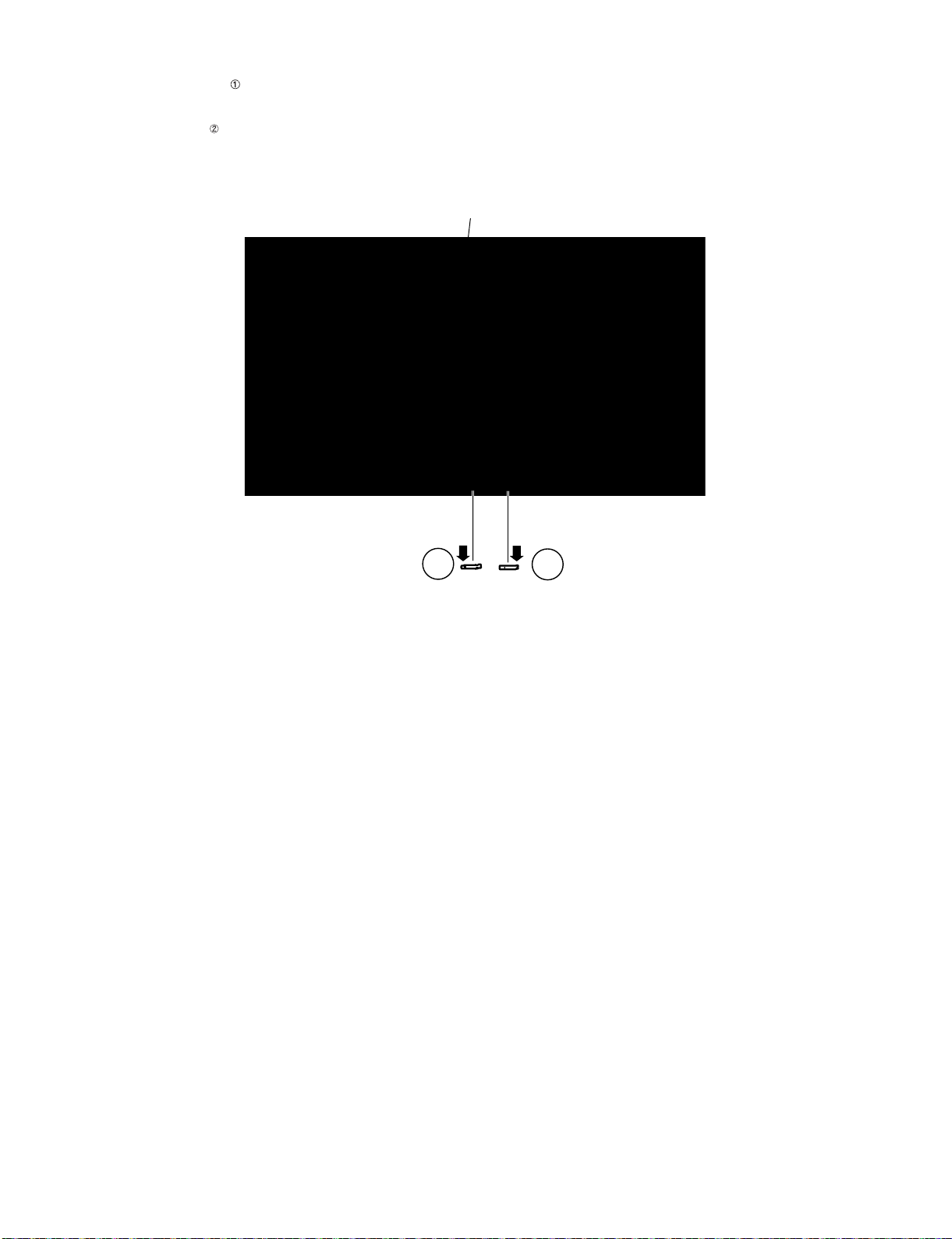
1. Removing of Stand Unit and Rear Cabinet Ass’y.
1. Remove the 4 lock screws and detach the Stand Unit .
2. Remove the 1 lock screw and detach the AC Cord Cover .
3. Disconnect AC wire and detach the AC Cord .
4. Remove the 10 lock screws , 2 lock screws , 18 lock screws and detach the Rear Cabinet Ass’y .
䎾䎤䎦䏀
䎕
䎛
䎔䎓
䎜
䎵䏈䏄䏕䎃䎦䏄䏅䏌䏑䏈䏗䎃
䎤䏖䏖䎊䏜
䎶䏗䏄䏑䏇䎃䎸䏑䏌䏗
䎔
䎚
䎛
䎘
䎤䎦䎃䎦䏒䏕䏇
䎖
䎗
䎤䎦䎃䎦䏒䏕䏇䎃䎦䏒䏙䏈䏕
LC-60/70LE650U/C6500U/LE657U,LC-60/70LE755U/LE757U/LE857U/C7500U
4 – 2
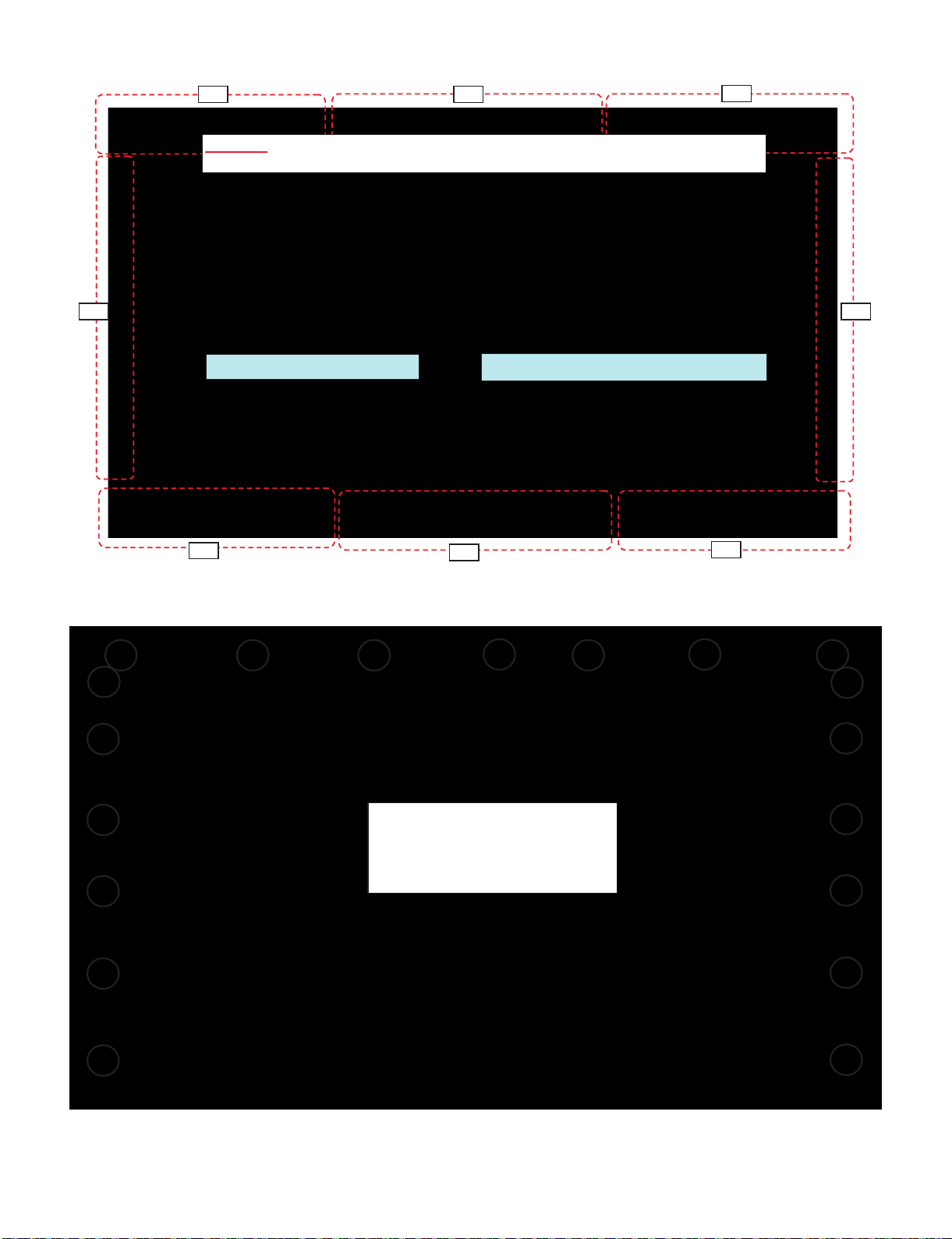
[Precautions when fixing the Rear Cabinet]
When fixing the Rear Cabinet, be careful not to catch the backlight LED harness, speaker harness and other harnesses in it.
• The hooks on the external wall of the Rear Cabinet are fitted in the Front Cabinet Ass’y. After putting the Rear Cabinet in place, fit the hooks
securely; then tighten the screws.
(Work method of Rear Cabinet fixation)
(Front Cabinet Ass’y/Rear Cabinet fingernail fixation place)
Rear Cabinet
(Mat parts)
Front Cabinet Ass'y
(Luster parts)
There is a gap without the fingernail fitting in completely only when covering
with Rear Cabinet.
It becomes the factor of a gap increase of Front Cabinet Ass'y/Rear Cabinet
and the Rear Cabinet misregistration.
Please tighten the screw after Rear Cabinet is firmly pushed, and the
fingernail is confirmed.
17 places
LC-60/70LE650U/C6500U/LE657U,LC-60/70LE755U/LE757U/LE857U/C7500U
4 – 3
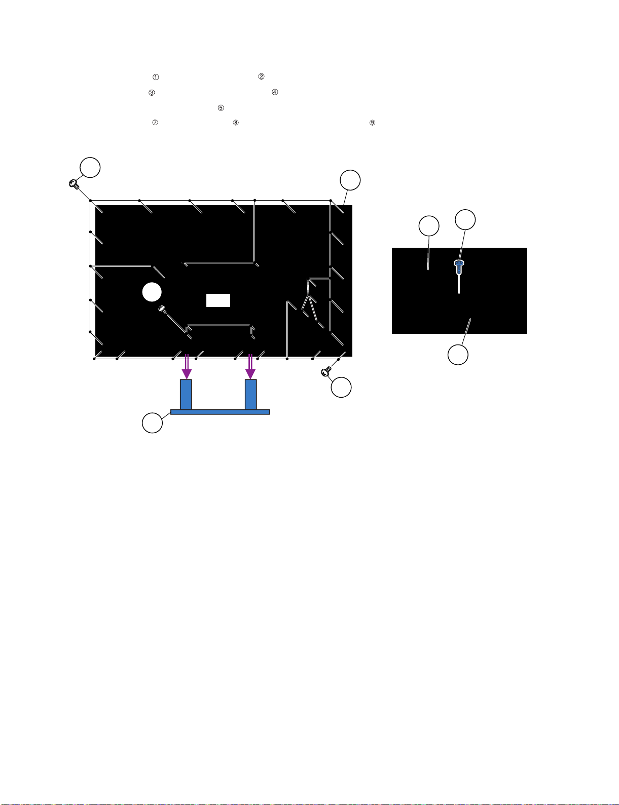
2. Removing of Speaker (L/R), KEY Unit and Bottom Cover.
1. Remove the 2 lock screws and detach the Speaker (L) , Speaker (R) .
2. Disconnect the SP wire.
3. Disconnect the RC wire.
4. Detach the KEY Unit Ass’y .
5. Disconnect the KM wire.
6. Remove the 2 Hooks and detach the KEY Unit from Key Button .
7. Remove the 1 lock screw , 6 Hooks and detach the Bottom Cover-R and Bottom Cover-L .
8. Remove the 1 lock screw and detach the Wi-Fi Hoder .
9. Detach the Wi-Fi Unit from Wi-Fi Holder .
10.Disconnect the UB wire.
11.Detach the BLUETOOTH Unit from Bottom Cover-R .(LC-60LE657U Only)
12.Disconnect the BT wire.(LC-60LE657U Only)
LA
PD
LV
l
PL
LV
UB
䎫䏒䏒䏎
䎾䎶䎳䏀
䎶䏓䏈䏄䏎䏈䏕䎃䎋䎵䎌
䎶䏓䏈䏄䏎䏈䏕䎃䎋䎯䎌
䎥䏒䏗䏗䏒䏐䎃
䎦䏒䏙䏈䏕䎐䎵
䎥䏒䏗䏗䏒䏐
䎦䏒䏙䏈䏕䎐䎯
䎛
䎜
䎔䎔
䎕
䎔䎓
䎔
䎰䎤䎬䎱䎃䎸䏑䏌䏗
䎫䏒䏒䏎 䎫䏒䏒䏎
[SP]
[RC]
䎔䎓
[KM]
6
3
5 Key Button
KEY Unit
KEY Unit
Ass'y
䎺䏌䎐䎩䏌䎃䎸䏑䏌䏗䎺䏌䎐䎩䏌䎃䎸䏑䏌䏗
䎺䏌䎐䎩䏌䎃䎫䏒䏏䏇䏈䏕䎺䏌䎐䎩䏌䎃䎫䏒䏏䏇䏈䏕
䎾䎸䎥䏀䎾䎸䎥䏀
䎔䎕
䎔䎖
䎔䎗
䎔䎘
䎥䎯䎸䎨䎷䎲䎲䎷䎫䎃
䎸䏑䏌䏗
䎥䎯䎸䎨䎷䎲䎲䎷䎫䎃
䎸䏑䏌䏗
䎾䎥䎷䏀䎾䎥䎷䏀
LC-60/70LE650U/C6500U/LE657U,LC-60/70LE755U/LE757U/LE857U/C7500U
4 – 4
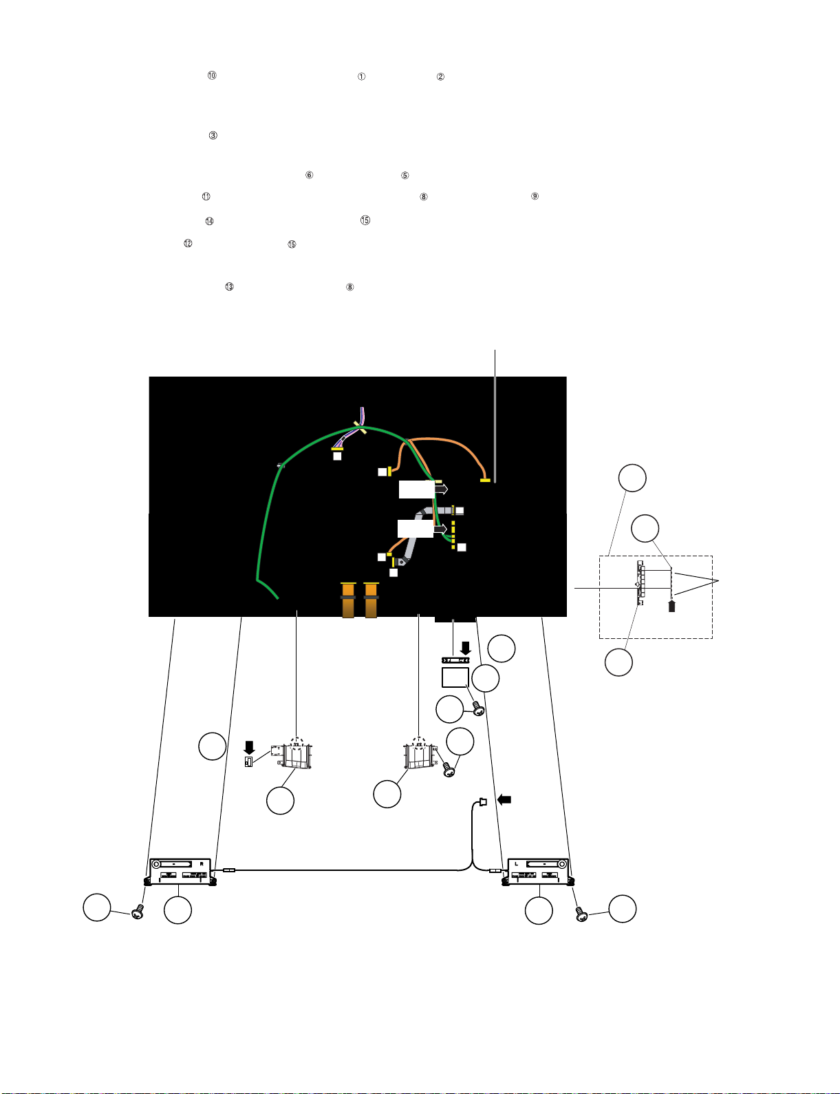
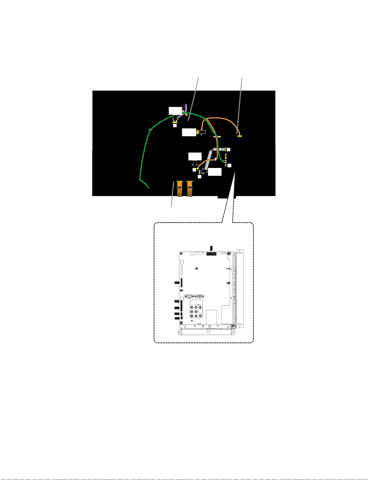
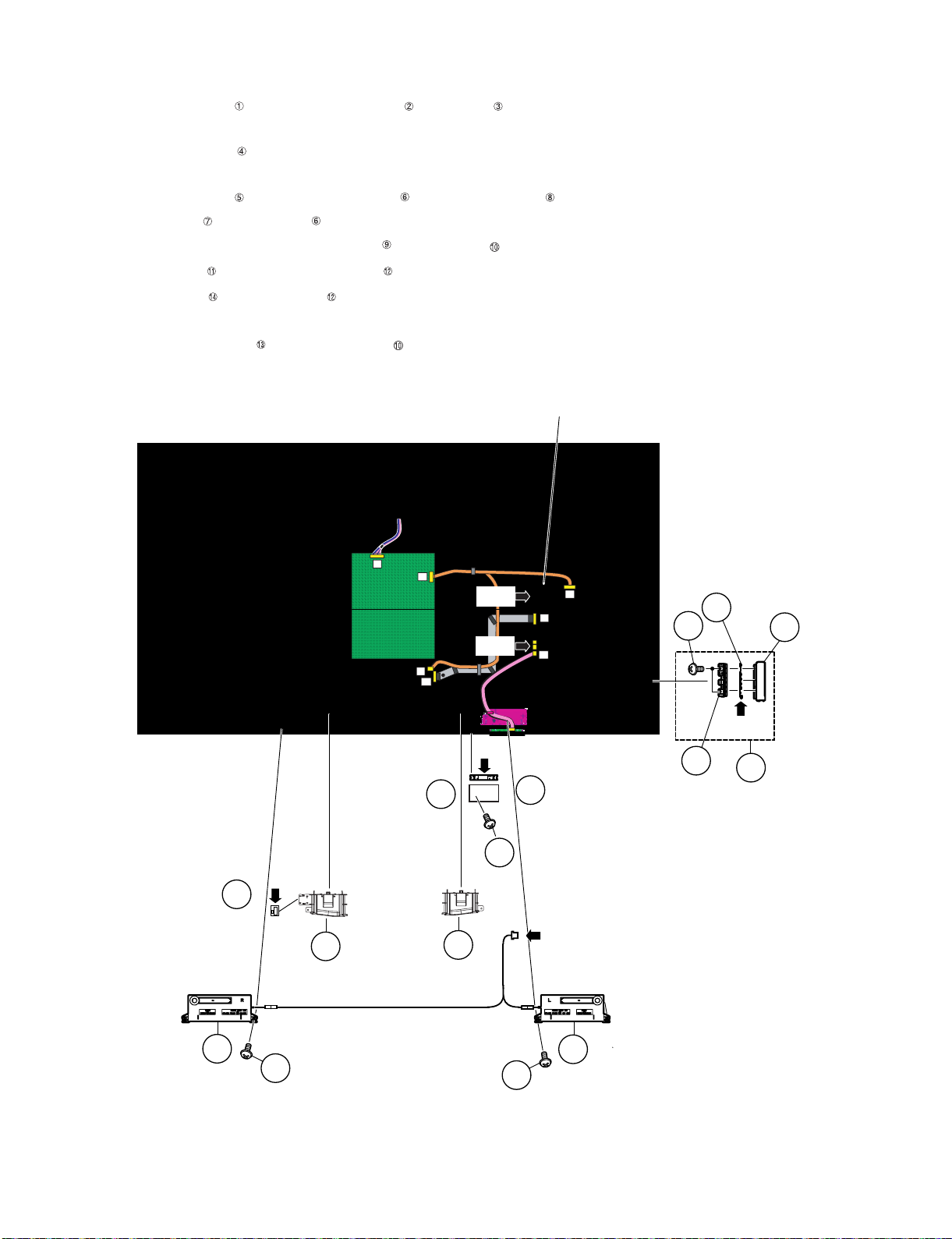
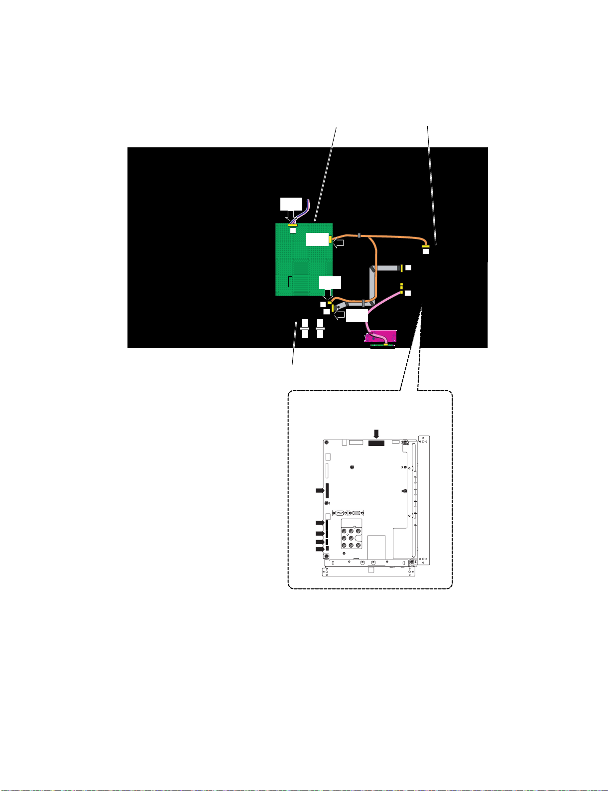
3. Removing of Connectors
1. Disconnect the following connectors from the MAIN Unit. (PD, LV, RC, UB, BT, IR) (for LC-60LE657U)
2. Disconnect the following connectors from the MAIN Unit. (PD, LV, RC, UB) (for LC-60LE650U/C6500U)
3. Disconnect the following connectors from the POWER/LED DRIVER Unit. (PD, LA)
4. Disconnect the following connectors from the LCD CONTROL Unit. (LV, PL)
LA
PD
LV
l
PL
LV
UB
䎾䎳䎧䏀
䎾䎯䎤䏀
䎯䎦䎧䎃䎦䎲䎱䎷䎵䎲䎯䎃䎸䏑䏌䏗
䎰䎤䎬䎱䎃䎸䏑䏌䏗
䎳䎲䎺䎨䎵䎒䎯䎨䎧䎃䎧䎵䎬䎹䎨䎵䎃䎸䏑䏌䏗
䎰䎤䎬䎱䎃䎸䏑䏌䏗
[UB]
[RC]
[IR]
[BT]
[LV]
[PD]
䎾䎳䎯䏀
䎾䎯䎹䏀
LC-60/70LE650U/C6500U/LE657U,LC-60/70LE755U/LE757U/LE857U/C7500U
4 – 5
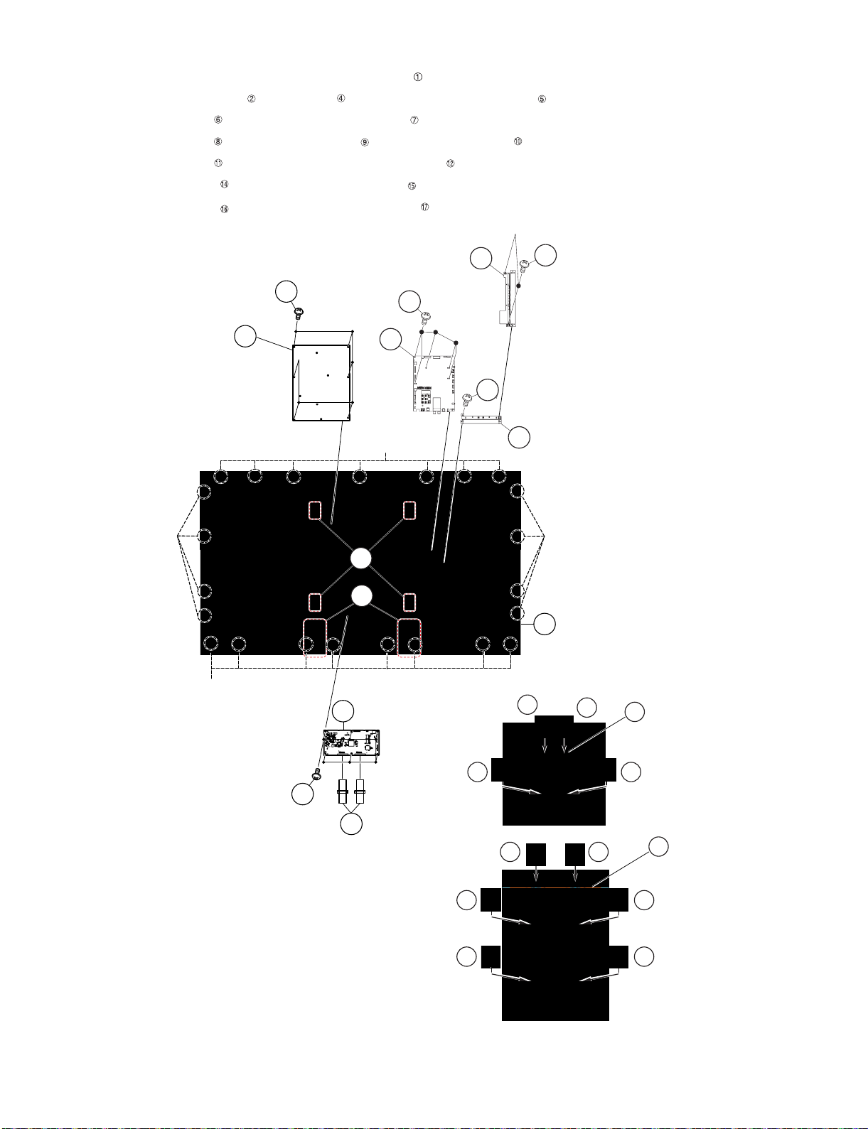
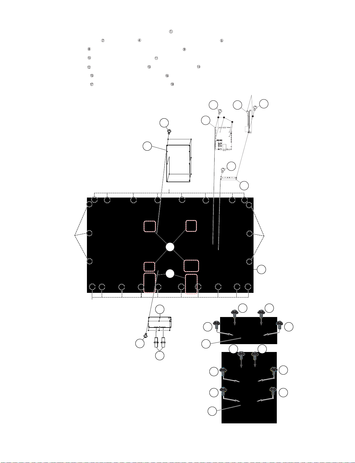
4. Removing of 60” LCD Panel Module Unit, LCD CONTROL Unit, MAIN Unit, POWER/LED DRIVER Unit.
1. Remove the 23 Hooks and detach the 60” LCD Panel Module Unit .
2. Remove the 2 Connecting Cords , 6 lock screws and detach the LCD CONTROL Unit .
3. Remove the 2 lock screws and detach the Terminal Angle Side .
4. Remove the 6 lock screws and detach the MAIN Unit and Terminal Angle Bottom .
5. Remove the 6 lock screws and detach the POWER/LED DRIVER Unit .
6. Remove the 12 lock screws and detach the 2 Stand Fix Angle .
7. Remove the 16 lock screws and detach the 4 VESA Angle Ass’y .
䎔䎕
䎔䎔
䎘
䎗
䎕
䎯䎦䎧䎃䎦䎲䎱䎷䎵䎲䎯
䎃䎸䏑䏌䏗
䎦䏒䏑䏑䏈䏗䏌䏑䏊䎃䎦䏒䏕䏇
䎳䎲䎺䎨䎵䎒
䎯䎨䎧䎃䎧䎵䎬䎹䎨䎵
䎃䎸䏑䏌䏗
䎙䎓䎅䎯䎦䎧䎃䎳䏄䏑䏈䏏䎃䎰䏒䏇䏘䏏䏈䎃䎸䏑䏌䏗
䎹䎨䎶䎤䎃䎤䏑䏊䏏䏈䎃䎤䏖䏖䎊䏜
䎔
䎫䏒䏒䏎
䎫䏒䏒䏎
䎫䏒䏒䏎
䎫䏒䏒䏎
䎶䏗䏄䏑䏇䎃䎩䏌䏛䎃䎤䏑䏊䏏䏈
9
MAIN
Unit
7Terminal Angle Side
10
16
16
16 16
14
14 14
14
14
14
17
15
Terminal Angle
Bottom
8
6
8
17
15
LC-60/70LE650U/C6500U/LE657U,LC-60/70LE755U/LE757U/LE857U/C7500U
4 – 6
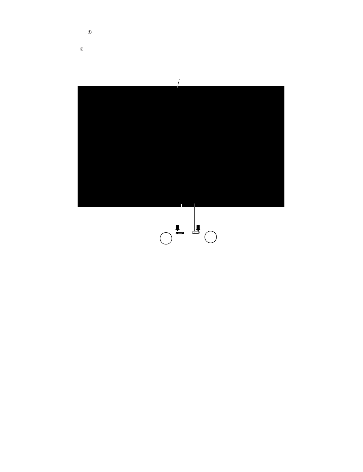
5. Removing of R/C OPC Unit, ICON Unit, Wi-Fi Unit, BLUETOOTH Unit.
1. Detach the R/C OPC Unit .
2. Disconnect the RA wire.
3. Detach the ICON Unit .
4. Disconnect the CI wire.
䎩䏕䏒䏑䏗䎃䎦䏄䏅䏌䏑䏈䏗䎃䎤䏖䏖䏃䏜
䎬䎦䎲䎱䎃䎸䏑䏌䏗
䎵䎒䎦䎃䎲䎳䎦䎃䎸䏑䏌䏗
䎾䎦䎬䏀
䎾䎵䎤䏀
䎔
䎕
LC-60/70LE650U/C6500U/LE657U,LC-60/70LE755U/LE757U/LE857U/C7500U
4 – 7
[2] REMOVING OF MAJOR PARTS (LC-70LE650U/C6500U/LE657U)
1. Removing of Stand Unit and Rear Cabinet Ass’y.
1. Remove the 4 lock screws and detach the Stand Unit .
2. Remove the 1 lock screw and detach the AC Cord Cover .
3. Disconnect AC wire and detach the AC Cord .
4. Remove the 9 lock screws and 21 lock screws and detach the Rear Cabinet Ass’y .
䎾䎤䎦䏀
䎕
䎜
䎛
䎵䏈䏄䏕䎃䎦䏄䏅䏌䏑䏈䏗䎃
䎤䏖䏖䎊䏜
䎶䏗䏄䏑䏇䎃䎸䏑䏌䏗
䎔
䎚
䎘
䎤䎦䎃䎦䏒䏕䏇
䎖
䎗
䎤䎦䎃䎦䏒䏕䏇䎃䎦䏒䏙䏈䏕
LC-60/70LE650U/C6500U/LE657U,LC-60/70LE755U/LE757U/LE857U/C7500U
4 – 8
[Precautions for assembly]
(Front Cabinet Ass’y/Rear Cabinet Ass’y fingernail fixation place)
Push
Push
Push
Push
Push
Push
Push
Push
CAUTION
Set it so that there may not be a clearance between Front Cabinet Ass'y and Rear Cabinet Ass'y.
There is a gap without the fingernail fitting
in completely only when covering with Rear Cabinet Ass'y.
The fingernail is surely fixed when Rear cabinet Ass'y is
firmly pushed, and the gap disappears.
19
places
LC-60/70LE650U/C6500U/LE657U,LC-60/70LE755U/LE757U/LE857U/C7500U
4 – 9
2. Removing of Speaker (L/R) and KEY Unit.
1. Disconnect the SP wire.
2. Remove the 2 lock screws and detach the Speaker (L) , Speaker (R) .
3. Disconnect the RC wire.
4. Detach the KEY Unit Ass’y .
5. Disconnect the KM wire.
6. Remove the 2 lock screws and detach the Key Button from Key Button Cover .
7. Detach the KEY Unit from Key Button .
8. Remove the 6 Hooks and detach the Bottom Cover-L Bottom Cover-R .
9. Remove the 1 Screw and detach the Wi-Fi Holder .
10.Detach the Wi-Fi Unit from Wi-Fi Holder .
11.Disconnect the UB wire.
12.Detach the BLUETOOTH Unit from Bottom Cover-R .(LC-70LE657U Only)
13.Disconnect the BT wire.(LC-70LE657U Only)
LA
PD
PD
LV
PL
LW
UB
䎾䎶䎳䏀
䎾䎮䎰䏀
䎶䏓䏈䏄䏎䏈䏕䎃䎋䎵䎌
䎶䏓䏈䏄䏎䏈䏕䎃䎋䎯䎌
䎥䏒䏗䏗䏒䏐
䎦䏒䏙䏈䏕䎐䎯
䎥䏒䏗䏗䏒䏐
䎦䏒䏙䏈䏕䎐䎵
䎔䎓
䎜
䎖
䎕
䎰䎤䎬䎱䎃䎸䏑䏌䏗
䎔
䎫䏒䏒䏎
䎫䏒䏒䏎
䎔
䎘
䎙
䎚
䎛
䎗
䎮䏈䏜䎃䎥䏘䏗䏗䏒䏑
䎮䎨䎼䎃䎸䏑䏌䏗
䎮䎨䎼䎃䎸䏑䏌䏗䎃䎤䏖䏖䏃䏜
䎮䏈䏜䎃䎥䏘䏗䏗䏒䏑䎃䎦䏒䏙䏈䏕
䎺䏌䎐䎩䏌䎃䎸䏑䏌䏗
䎾䎸䎥䏀
䎔䎕
䎺䏌䎐䎩䏌䎃
䎫䏒䏏䏇䏈䏕
䎺䏌䎐䎩䏌䎃
䎫䏒䏏䏇䏈䏕
䎔䎗
䎔䎔
䎔䎖
䎥䎯䎸䎨䎷䎲䎲䎷䎫䎃
䎸䏑䏌䏗
䎥䎯䎸䎨䎷䎲䎲䎷䎫䎃
䎸䏑䏌䏗
䎾䎥䎷䏀䎾䎥䎷䏀
[SP]
[RC]
LC-60/70LE650U/C6500U/LE657U,LC-60/70LE755U/LE757U/LE857U/C7500U
4 – 10
3. Removing of Connectors
1. Disconnect the following connectors from the MAIN Unit. (PD, LV, RC, UB, BT/IR) (for LC-70LE657U)
2. Disconnect the following connectors from the MAIN Unit. (PD, LV, RC, UB) (for LC-70LE650U/C6500U)
3. Disconnect the following connectors from the POWER/LED DRIVER Unit. (PD, LA)
4. Disconnect the following connectors from the LCD CONTROL Unit. (LV, PL)
LA
PD
PD
LV
PL
LW
UB
䎾䎳䎧䏀
䎾䎯䎤䏀
䎯䎦䎧䎃䎦䎲䎱䎷䎵䎲䎯䎃䎸䏑䏌䏗
䎰䎤䎬䎱䎃䎸䏑䏌䏗
䎳䎲䎺䎨䎵䎒䎯䎨䎧䎃䎧䎵䎬䎹䎨䎵䎃䎸䏑䏌䏗
䎰䎤䎬䎱䎃䎸䏑䏌䏗
䎾䎳䎯䏀
䎾䎯䎹䏀
[UB]
[RC]
[IR]
[BT]
[LV]
[PD]
LC-60/70LE650U/C6500U/LE657U,LC-60/70LE755U/LE757U/LE857U/C7500U
4 – 11
4. Removing of 70” LCD Panel Module Unit, LCD CONTROL Unit, MAIN Unit, POWER/LED DRIVER Unit.
1. Remove the 24 Hooks and detach the 70” LCD Panel Module Unit .
2. Remove the 2 Connecting Cords , 6 lock screws and detach the LCD CONTROL Unit .
3. Remove the 6 lock screws and detach the POWER/LED DRIVER Unit .
4. Remove the 2 lock screws and detach the Terminal Side .
5. Remove the 6 lock screws and detach the MAIN Unit and Terminal Bottom .
6. Remove the 12 lock screws and detach the 2 Stand Fix Angle .
7. Remove the 16 lock screws and detach the 4 VESA Angle Ass’y .
䎔䎚 䎔䎚
䎔䎚 䎔䎚
䎔䎛
䎜
䎛
䎘
䎗
䎔䎘
䎔䎘
䎔䎘
䎔䎘
䎔䎘 䎔䎘
䎔䎙
䎕
䎶䏗䏄䏑䏇䎃䎩䏌䏛䎃䎤䏑䏊䏏䏈
䎯䎦䎧䎃䎦䎲䎱䎷䎵䎲䎯䎃䎸䏑䏌䏗
䎦䏒䏑䏑䏈䏗䏌䏑䏊䎃䎦䏒䏕䏇
䎹䎨䎶䎤䎃䎤䏑䏊䏏䏈䎃䎤䏖䏖䏃䏜
䎳䎲䎺䎨䎵䎒
䎯䎨䎧䎃䎧䎵䎬䎹䎨䎵
䎃䎸䏑䏌䏗
䎚䎓䎅䎯䎦䎧䎃䎳䏄䏑䏈䏏䎃
䎰䏒䏇䏘䏏䏈䎃䎸䏑䏌䏗
䎔
䎫䏒䏒䏎
䎫䏒䏒䏎
䎫䏒䏒䏎
䎫䏒䏒䏎
13
11
Terminal Side
14
Terminal
Bottom
12
10
12
MAIN Unit
18
16
LC-60/70LE650U/C6500U/LE657U,LC-60/70LE755U/LE757U/LE857U/C7500U
4 – 12
5. Removing of R/C OPC Unit, ICON Unit, Wi-Fi Unit, BLUETOOTH Unit.
1. Detach the R/C OPC Unit .
2. Disconnect the RA wire.
3. Detach the ICON Unit .
4. Disconnect the CI wire.
䎩䏕䏒䏑䏗䎃䎦䏄䏅䏌䏑䏈䏗䎃䎤䏖䏖䏃䏜
䎬䎦䎲䎱䎃䎸䏑䏌䏗
䎵䎒䎦䎃䎲䎳䎦䎃䎸䏑䏌䏗
䎾䎦䎬䏀
䎾䎵䎤䏀
䎔
䎕
LC-60/70LE650U/C6500U/LE657U,LC-60/70LE755U/LE757U/LE857U/C7500U
4 – 13
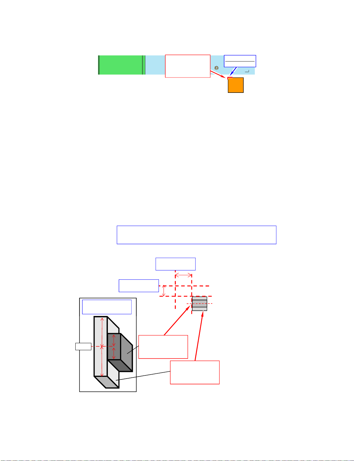
[3] The location putting on the heat measure sheet (LC-60/70LE650U/C6500U/LE657U)
1. MAIN PWB Unit
• LC-60LE650U/C6500U/LE657U
• LC-70LE650U/6500U/LE657U
(1) Stick***
PSPAZD031WJKZ
MAIN CPU COOLER
(20*20*7T)
(20 20 7T)
Stick standard
Punch mark
30mm from center
of screw hole.
20mm from center
of screw hole.
First , please put "PSPAZC805WJKZ" along the standard point.
next , please put "PSPAZC854WJKZ" on the center of "PSPAZC805WJKZ".
( Don't protrude from edge of "PSPAZC805WJKZ".)
Side View of
MAIN•CPU COOLER
(2) Stick *****
PSPAZC805WJKZ
(MAIN-CPU COOLER)
(25x25x8mm)
(3) Stick *****
PSPAZC854WJKZ
(MAIN-CPU COOLER)
(25x15x8.5mm)
Center
LC-60/70LE650U/C6500U/LE657U,LC-60/70LE755U/LE757U/LE857U/C7500U
4 – 14
[4] Precautions for assembly (LC-60/70LE650U/C6500U/LE657U)
1. Points to be checked and precautions when servicing the unit
Mount the main PWB Ass’y on the backlight chassis and check that the EMI-prevention parts are not peeled and twisted from the access holes. (The
EMI-prevention parts, conductive nonwoven fabric gaskets, must be seen from the access holes.)
[Countermeasure]
Attach the conductive nonwoven fabric gaskets on the shielded case on the main PWB.
• LC-60LE650U/C6500U/LE657U
.
Back side
Stick a conductor seat in the projection part.
(1) Prepare***
LANGKD145WJFW
TERMINAL SIDE
(2) Stick ***
PSPAZC690WJZZ
CONDUCTR:8x255
Positioning Positioning
Back side
Stick a conductor seat in the projection part .
Positioning
Positioning
(1) Prepare***
LANGKD146WJFW
TERMINAL BOTTOM
(2) Stick ***
PSPAZC691WJZZ
CONDUCTR:8x180
PSPAZC691WJZZ
CONDUCTR:8x180
 Loading...