


FO-475TH
1 - 1
UX-258TH
FO-475TH
No. 00ZUX258THSME
CHAPTER 1. GENERAL DESCRIPTION
[1] Specifications ............................................ 1-1
[2] Operation panel......................................... 1-2
[3] Transmittable documents.......................... 1-3
[4] Installation ................................................. 1-4
[5] Quick reference guide ............................... 1-7
CHAPTER 2. ADJUSTMENTS
[1] Adjustments............................................... 2-1
[2] Diagnostics and service soft switch .......... 2-2
[3] Troubleshooting...................................... 2-17
[4] Error code table....................................... 2-18
CHAPTER 3. MECHANISM BLOCKS
[1] General description .................................. 3-1
[2] Disassembly and assembly
procedures ....................................... 3-3
CHAPTER 4. DIAGRAMS
[1] Block diagram ............................................4-1
[2] Wiring diagram .......................................... 4-2
[3] Point-to-point diagram............................... 4-3
CHAPTER 5. CIRCUIT DESCRIPTION
[1] Circuit description ..................................... 5-1
[2] Circuit description of control PWB ............ 5-2
[3] Circuit description of TEL/LIU PWB .......... 5-8
[4] Circuit description of
power supply PWB............................5-11
[5] Circuit description of CIS unit...................5-11
CHAPTER 6. CIRCUIT SCHEMATICS AND
P ARTS LA YOUT
[1] Control PWB circuit ................................... 6-1
[2] TEL/LIU PWB circuit.................................. 6-9
[3] Power supply PWB circuit ...................... 6-11
[4] Operation panel PWB circuit ................... 6-13
CHAPTER 7. OPERATION FLOWCHART
[1] Protocol ..................................................... 7-1
[2] Power on sequence................................... 7-2
CHAPTER 8. OTHERS
[1] Service tools ............................................. 8-1
[2] IC signal name .......................................... 8-4
P ARTS GUIDE
CONTENTS
Parts marked with " " is important for maintaining the safety of the set. Be sure to replace these parts with specified ones for
maintaining the safety and performance of the set.
This document has been published to be used
for after sales service only.
The contents are subject to change without notice.
SHARP CORPORATION
SERVICE MANUAL
FACSIMILE
UX-258
MODEL FO-475

1 – 2
UX-258TH
FO-475TH
(Danish) ADVARSEL !
Lithiumbatteri-Eksplosionsfare ved fejlagtig håndtering.
Udskiftning må kun ske med batteri af samme fabrikat og type.
Levér det brugte batteri tilbage til leverandoren.
(English) Caution !
Danger of explosion if battery is incorrectly replaced.
Replace only with the same or equivalent type
recommended by the equipment manufacturer.
Discard used batteries according to manufacturer’s
instructions.
(Finnish) VAROITUS
Paristo voi räjähtää, jos se on virheellisesti asennettu.
Vaihda paristo ainoastaan laitevalmistajan suosittelemaan
tyyppiin. Hävitä käytetty paristo valmistajan ohjeiden
mukaisesti.
(French) ATTENTION
Il y a danger d’explosion s’ il y a remplacement incorrect
de la batterie. Remplacer uniquement avec une batterie du
même type ou d’un type recommandé par le constructeur.
Mettre au rébut les batteries usagées conformément aux
instructions du fabricant.
(Swedish) VARNING
Explosionsfare vid felaktigt batteribyte.
Använd samma batterityp eller en ekvivalent
typ som rekommenderas av apparattillverkaren.
Kassera använt batteri enligt fabrikantens
instruktion.
(German) Achtung
Explosionsgefahr bei Verwendung inkorrekter Batterien.
Als Ersatzbatterien dürfen nur Batterien vom gleichen Typ oder
vom Hersteller empfohlene Batterien verwendet werden.
Entsorgung der gebrauchten Batterien nur nach den vom
Hersteller angegebenen Anweisungen.
CAUTION FOR BATTERY REPLACEMENT

1 – 1
UX-258TH
FO-475TH
CHAPTER 1. GENERAL DESCRIPTION
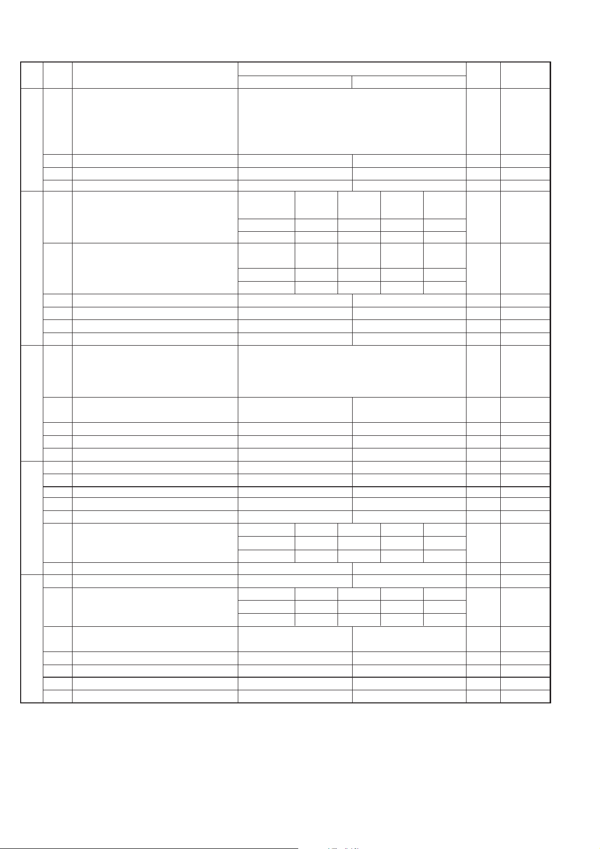
[1] Specifications
Automatic dialing: Rapid Key Dialing: 10 numbers
Speed Dialing: 20 numbers
Fax paper: Initial starter roll (included with fax
machine): 10 m roll
Recommended replacement roll:
FO-40PR 50 m roll
Automatic document feeder: 10 sheets max.
Paper cutting method: Automatic cutter
Modem speed: 9600 bps with automatic fallback to
7200, 4800, or 2400 bps
Transmission time* : Approx. 15 seconds (Sharp special mode)
Display: 7 x 5 dots, 1 line by 16-digit display
Reception modes: TEL, FAX, TEL/FAX, ANS.
Resolution: Horizontal:
8 dots/mm
Vertical:
Standard: 3.85 lines/mm
Fine/Halftone: 7.7 lines/mm
Super fine: 15.4 lines/mm
Recording system: Thermal recording
Halftone (grayscale): 64 levels
Applicable telephone line: Public switched telephone network/PBX
Compatibility: ITU-T (CCITT) G3 mode
Configuration: Half-duplex, desktop transceiver
Compression scheme: MH, MR, Sharp special mode
Scanning method: Sheet-feeder CIS (Contact Image Sensor)
Effective recording width: 210 mm max.
Input document size: Automatic feeding:
Width 148 to 216 mm
Length 140 to 297 mm
Manual feeding:
Width 148 to 216 mm
Length 140 to 600 mm
Effective scanning width: 210 mm max.
Contrast control: Automatic/Dark selectable
Copy function: Standard
Telephone function: Standard
(cannot be used for incoming/outgoing
if power fails)
Power requirements: 220-240 V, 50 Hz
Operating temperature: 5 to 35°C
Humidity: Maximum: 85 %
Power consumption: Stand-by: 6.0 W
Maximum: 120 W
Dimensions: Width: 308 mm
Depth: 256 mm
Height: 138 mm
Weight: Approx. 2.6 kg
(without attachements)
* Based on ITU-T (CCITT) T est Chart #1 at standard resolution in Sharp
special mode, excluding time for protocol signals (i.e., ITU-T phase C
time only).
As a part of our policy of continuous improvement, SHARP reserves the right to make design and specification changes for procduct
improvement without prior notice. The performance specifications figures indicated are nominal values of production units. There may be some
deviation from these values in individual units.
1 – 2
UX-258TH
FO-475TH
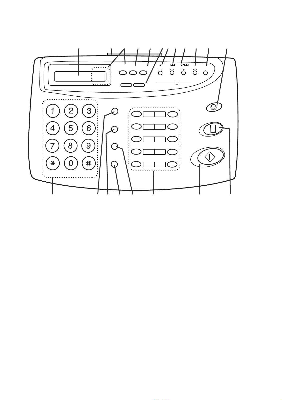
[2] Operation panel
TEL FAX
RESOLUTION
VOLUME
ANS.
SPEED DIAL
REDIAL
SPEAKER
01
02
03
04
05
06
07
08
09
10/POLL
ABC
DEF
JKL
MNO
GHI
TUV
WXYZ
PQRS
START/MEMORY
STOP
COPY/HELP
HOL/SEARCH
TEL/FAX
DIGITAL
ANSWERING
SYSTEM
1. Display
This displays messages and prompts during operation and
programming.
2. PANEL RELEASE
Pull this release toward you to open the operation panel.
3. RECEPTION MODE key
Press this key to select the reception mode. An arrow in the
display will point to the currently selected reception mode.
4. FUNCTION key
Press this key to select various special function.
5. RESOLUTION key
Press this key to adjust the resolution and contrast before
sending or copying a document.
6. VOLUME keys
Press these keys to adjust the volume of the speaker when
the SPEAKER key has been pressed, or the volume of the
ringer at all other times.
7. REC key
Press this key to record a phone conversation or a message.
8. REPEAT key
Press this key to repeat playback of a message.
9. PLAY/SKIP key
Press this key to play recorded messages. During playback,
press it to skip forward to the next message.
10. DELETE key
Press this key to erase recorded messages.
11. REMINDER key
Press this key to send a fax and/or voice message to another
party or to yourself at a preset time.
12. STOP key
Press this key to stop operations before they are completed.
13. Number keys
Use these keys to dial numbers, and enter number and letters
during number/name storing procedures.
14. SPEED DIAL key
Press this key to dial a 2-digit Speed Dial number.
15. REDIAL key
Press this key to automatically redial the last number dialed.
16. SPEAKER key
Press this key to hear the line and fax tones through the
speaker when sending a document, or dialing a voice number.
Note: This is not a speakerphone. You must pick up the
handset to talk with the other party.
17. HOLD/SEARCH key
Press this key to search for an automatic dialing number,
or, during a phone conversation, press this key to put the
other party on hold.
18. Rapid Dial keys
Press one of these keys to dial a fax or voice number
automatically. (Note that you must attach the Rapid Key
labels.)
19. START/MEMORY key
Press this key to send or receive a document manually
when off hook.
20. COPY/HELP key
When a document is in the feeder, press this key to make
a copy. At any other time, press this key to print out the
Help List, a quick refernce guide to the opeation of your
fax.
11 12108 9
1
3 4 5
2
6
13 14
15
16 17 18
19 20
RECEPTION
MODE
FUNCTION
DOWN
UP
PLAY/SKIP
DELETE
REC
REPEAT
REMINDER
7
1 – 3
UX-258TH
FO-475TH
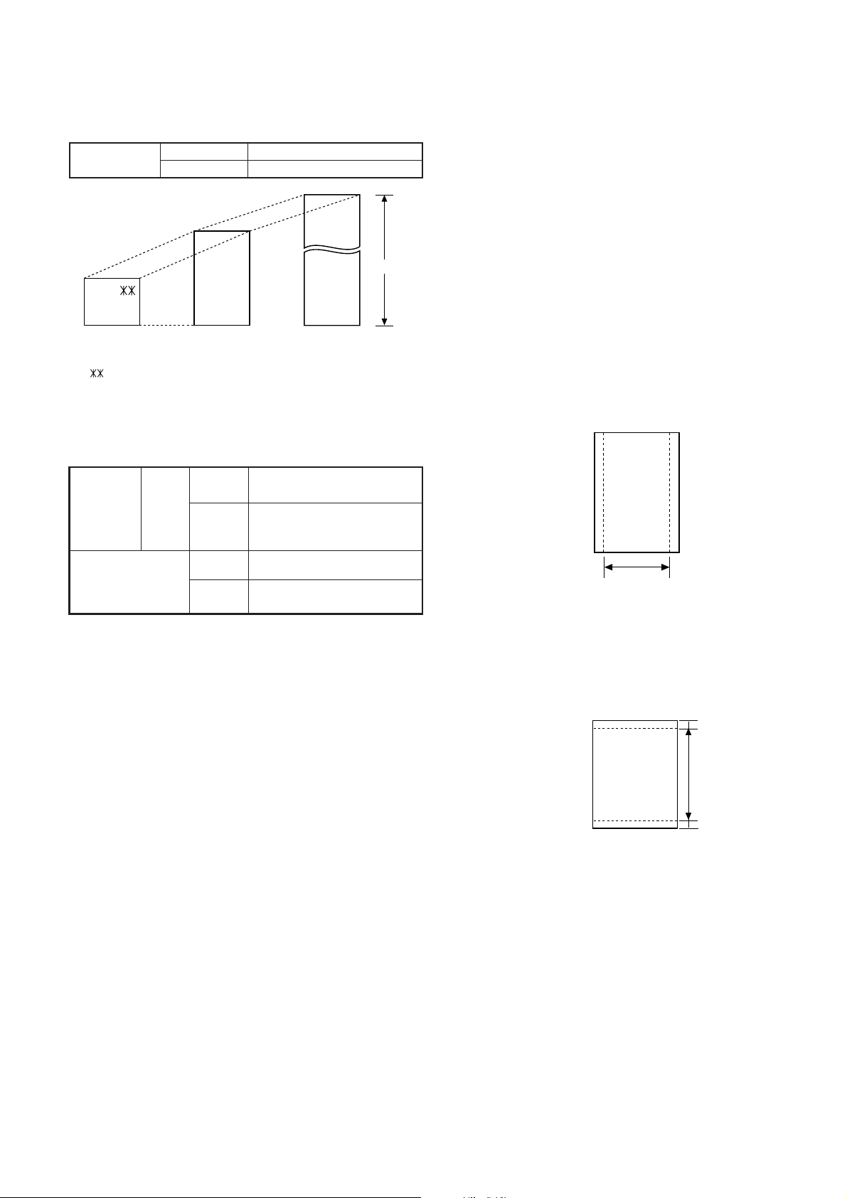
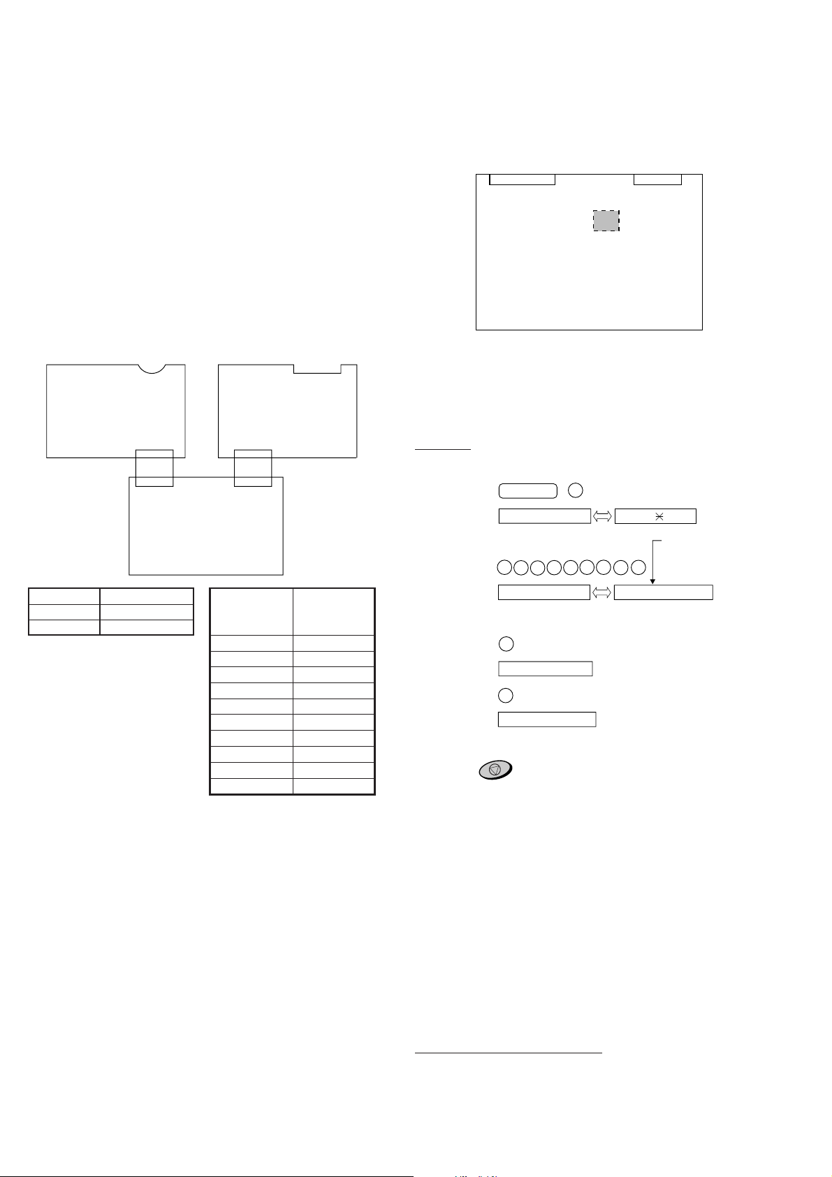
[3] Transmittable documents
1. Document Sizes
* With special sizes, only one sheet can be fed into the machine at a
time. Insert next page into feeder as current page is being scanned.
2. Paper Thickness & Weight
3. Document Types
• Normal paper
Documents handwritten in pencil (No. 2 lead or softer), fountain pen,
ball-point pen, or felt-tipped pen can be transmitted.
Documents of normal contrast duplicated by a copying machine can
also be transmitted.
• Diazo copy (blue print)
Diazo copy documents of a normal contrast may be transmitted.
• Carbon copy
A carbon copy may be transmitted if its contrast is normal.
4. Cautions on Transmitting Documents
• Documents written in yellow, greenish yellow, or light blue ink cannot
be transmitted.
• Ink, glue, and correcting fluid on documents must be dry before the
documents can be transmitted.
• All clips, staples and pins must be removed from documents be-fore
transmission.
• Patched (taped) documents should be copied first on a copier and
then the copies used for transmission.
• All documents should be fanned before insertion into the feeder to
prevent possible double feeds.
Normal size
width 148 – 216 mm
length 140 – 297 mm
5. Automatic Document Feeder Capacity
Number of pages that can be placed into the feeder at anytime is as
follows:
Normal size: max. ADF 10 sheets
Special size: single sheet only (manual feed)
NOTES:
• When you need to send or copy more pages than the feeder
limit, place additional pages in feeder when last page in
feeder is being scanned.
• Place additional pages carefully and gently in feeder .
If force is used, double-feeding or a document jam may
result.
6. Readable Width & Length
The readable width and length of a document are slightly smaller than
the actual document size.
Note that characters or graphics outside the effective document scan-
ning range will not be read.
• Readable width
210 mm, max.
• Readable length
This is the length of the document sent minus 4 mm from the top and
bottom edges.
Use document carrier sheet for smaller documents.
Readable width
Normal size
ADF 10
sheets
2.4 x 10
–3
–4.7 x 10
–3
inch
Thickness
Weight
0.15 x 10
–3
lbs/inch
2
Special size
Thickness
4.7 x 10
–3
–7.9 x 10
–3
inch
0.15 x 10
–3
–0.20 x 10
–3
lbs/inch
2
Weight
(Min.)
(Max.)
A4 size
(Max.)
140mm
297mm
600mm
148mm 216mm
[
Normal size
]
216mm
[
Special size
]
4mm
4mm
Readable length
1 – 4
UX-258TH
FO-475TH
7. Use of Document Carrier Sheet
A document carrier sheet must be used for the following documents.
• Those with tears.
• Those smaller than size 140 mm (W) x 140 mm (L).
• Carbon-backed documents
NOTE: To transmit a carbon-backed document, insert a white sheet of
paper between the carbon back of the document and the docu-
ment carrier.
• Those containing an easily separable writing substance (e.g., trac-
ing paper written on with a soft, heavy lead pencil).
NOTES: • When using the document carrier, carefully read the in-
structions written on the back.
• If the document carrier is dirty, clean it with a soft, moist
cloth, and then dry it before using for transmission.
• Do not place more than one document in the carrier at a
time.
[4] Installation
1. Site selection
T ake the following points into consideration when selecting a site for this
model.
ENVIRONMENT
• The machine must be installed on a level surface.
• Keep the machine away from air conditioners, heaters, direct sun-
light, and dust.
• Provide easy access to the front, back, and sides of the machine. In
particular, keep the area in front of the machine clear, or the original
document may jam as it comes out after scanning.
• The temperature should be between 5° and 35°C.
• The humidity should be between 30% and 85% (without conden-
sation).
ELECTRICITY
220-240 V, 50 Hz, earthed (2-prong) AC outlet is required.
Caution!
• Connection to a power source other than that specified will cause
damage to the equipment and is not covered under the warranty.
• If your area experiences a high incidence of lightning or power surges,
we recommend that you install a surge protector for the power and
telephone lines. Surge protectors can be purchased at most telephone
specialty stores.
If the machine is moved from a cold to a warm place...
If the machine is moved from a cold to a warm place, it is possible that
the reading glass may fog up, preventing proper scanning of documents
for transmission. T o remove the fog, turn on the power and wait approxi-
mately 2 hours before using the machine.
TELEPHONE JACK
A standard telephone jack must be located near the machine.
This is the telephone jack commonly used in most homes and offices.
• Plugging the fax machine into a jack which is not an jack may result
in damage to the machine or your telephone system. If you do not
know what kind of jack you have, or needed to have one installed,
contact the telephone company.
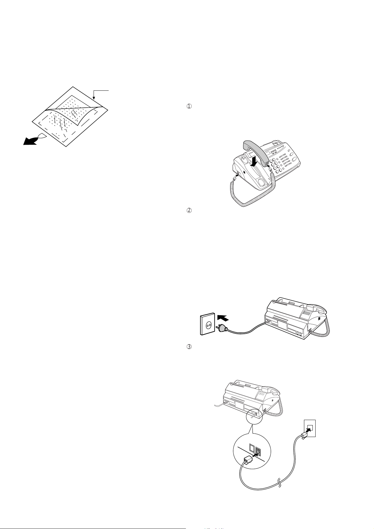
2. Connections
1
Connect the handset as shown and place it on the handset rest.
♦ Make sure the handset cord goes into the unmarked jack on the
side of the machine!
♦ Use the handset to make ordinary phone calls, or to transmit and
receive documents manually.
2
Plug the power cord into a 220-240 V, 50 Hz, earthed (2-prong) AC
outlet.
♦ Caution: Do not plug the power cord into any other kind of outlet.
This will damage the machine and is not covered under the
warranty.
Note: The shape of the plug is different in certain countries.
♦ The machine does not have a power on/off switch, so the power
is turned on and off by simply plugging or unplugging the power
cord.
Note: If your area experiences a high incidence of lightning or power
surges, we recommend that you install surge protectors for the
power and telephone lines. Surge protectors can be purchased
from your dealer or at most telephone specialty stores.
3
Insert one end of the telephone line cord into the "TEL. LINE" jack.
Insert the other end into a standard (RJ11C) single-line telephone
wall jack.
♦ Be sure to insert the telephone line cord into the "TEL. LINE"
jack. Do not insert into the "TEL. SET" jack.
Direction of insertion
Make print straight
across paper
E.G.
Place the document
carrier in the document
feeder with the clear film
side down
TEL.
SET
TEL.
LINE
1 – 5
UX-258TH
FO-475TH
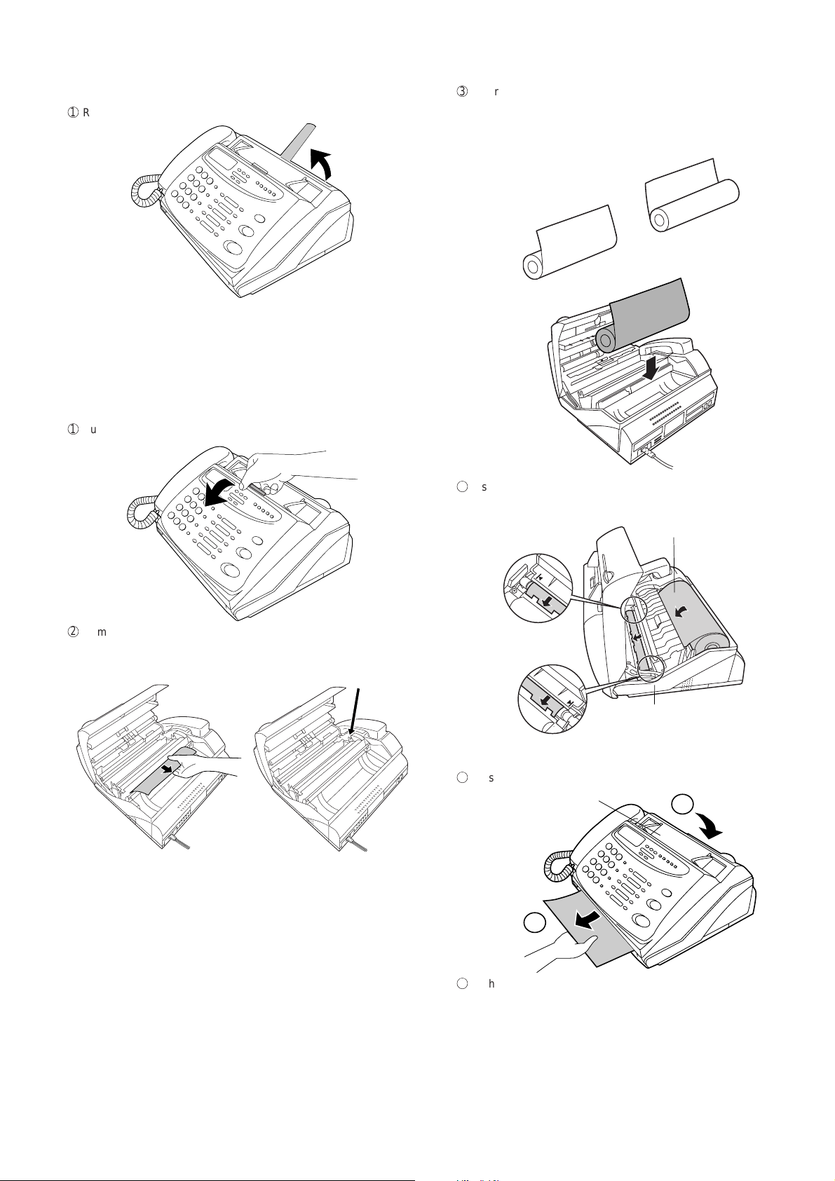
3. Original document support
1
Rotate the original document support so that it points straight out.
4. Loading the fax paper
• Your fax machine prints incoming faxes on a special kind of paper
called thermal paper.
• The fax’s print head creates text and images by applying heat to
the thermal paper.
Note: The power must be on (plug in the power cord) when loading
fax paper in the fax machine.
1
Pull the release marked PANEL RELEASE toward you and open the
operation panel.
2
Remove the packing paper from the paper compartment.
3
Unwrap the roll of fax paper and place it in the compartment.
• Important: The roll must be placed so that the leading edge of
the paper unrolls as shown. (The paper is only coated on one
side for printing. If the roll is placed backwards, the paper will
come out blank after printing.)
4
Insert the leading edge of the paper into the paper inlet. Continue to
push the paper through the inlet until it comes out of the opening in
the front of the fax.
5
Close the operation panel, making sure it clicks into place.
6
A short length of the fax paper will feed out and be cut off. (If this
doesn’t happen, repeat the loading procedure.)
Note: The fax has a built-in anti-curl mechanism that will help to reduce
paper curling problems. The anti-curl mechanism is more
effective at the beginning of the paper roll and less effective
towards the end.
Remove
cardboard
and tape
YES
NO!
Paper inlet
The paper will reappear here. Make
sure it is aligned between the arrows
on each side of the guide, and then
passes under the plate and out the
front of the fax.
1
2
Click!
Press here to close
1 – 6
UX-258TH
FO-475TH
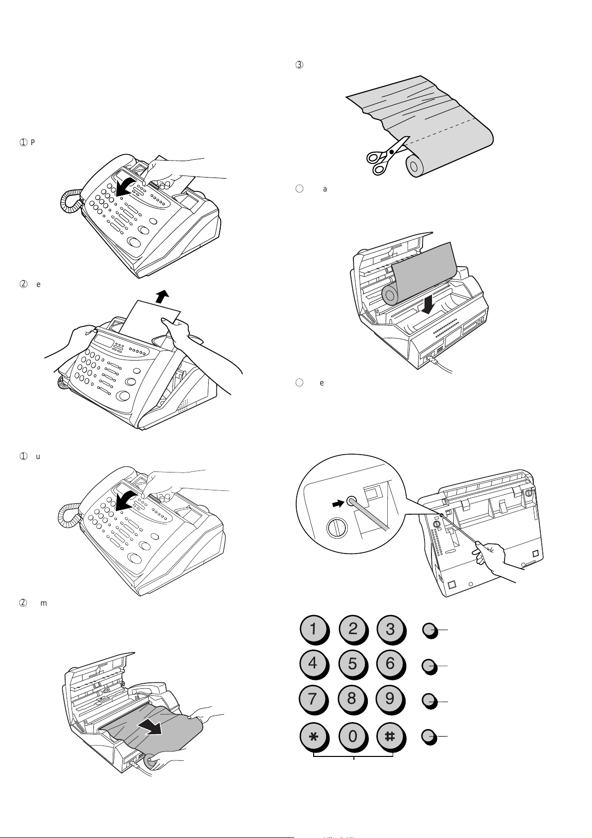
4. Clearing a jammed document
If the original document doesn’t feed properly during transmission or
copying, or DOCUMENT JAMMED appears in the display , first try press-
ing the START/MEMORY key. If the document doesn’t feed out, open
the operation panel and remove it.
Important: Do not try to remove a document without opening the op-
eration panel. This may damage the feeder mechanism.
1
Pull the release marked PANEL RELEASE toward you and open the
operation panel.
2
Remove the document.
5. Clearing jammed fax paper
1
Pull the release marked PANEL RELEASE toward you and open the
operation panel.
2
Remove the paper roll.
• If any pieces of paper are stuck in the cutter, remove them with
caution.
• Press the START/MEMORY key to reset the cutter.
3
Cut off the wrinkled part of the paper.
4
Reload the paper.
• Jammed fax paper is often caused by improper loading. Be sure
to carefully follow the instructions for paper loading given in "Load-
ing the Fax Paper" in page 1-5.
5
If the display still shows PAPER JAMMED
If the display still shows P APER JAMMED after you press the ST ART/
MEMORY key in Step 2 above, the cutter is still engaged in the cutting
position. To open the cutter , turn the fax up on its rear end and insert
any long, rod-like object with a flat or blunt end into the hole marked
CUTTER RESET. Continue to push the rod in until you feel it move a
lever inside the machine.
CUTTER
RESET
SPEED DIAL
REDIAL
HOLD/SEARCH
SPEAKER
ABC DEF
JKL MNOGHI
TUV WXYZ
PQRS
Press this key to delete
the letter highlighted by
the cursor.
Press this key to change
case.
Press this key to move
the cursor to the left.
Press this key to move
the cursor to the right.
Press either key repeatedly to select
one of the following symbols.
1 – 7
UX-258TH
FO-475TH
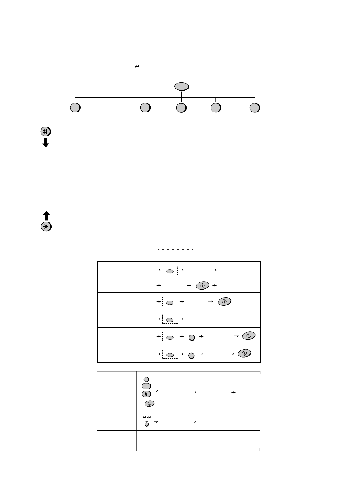
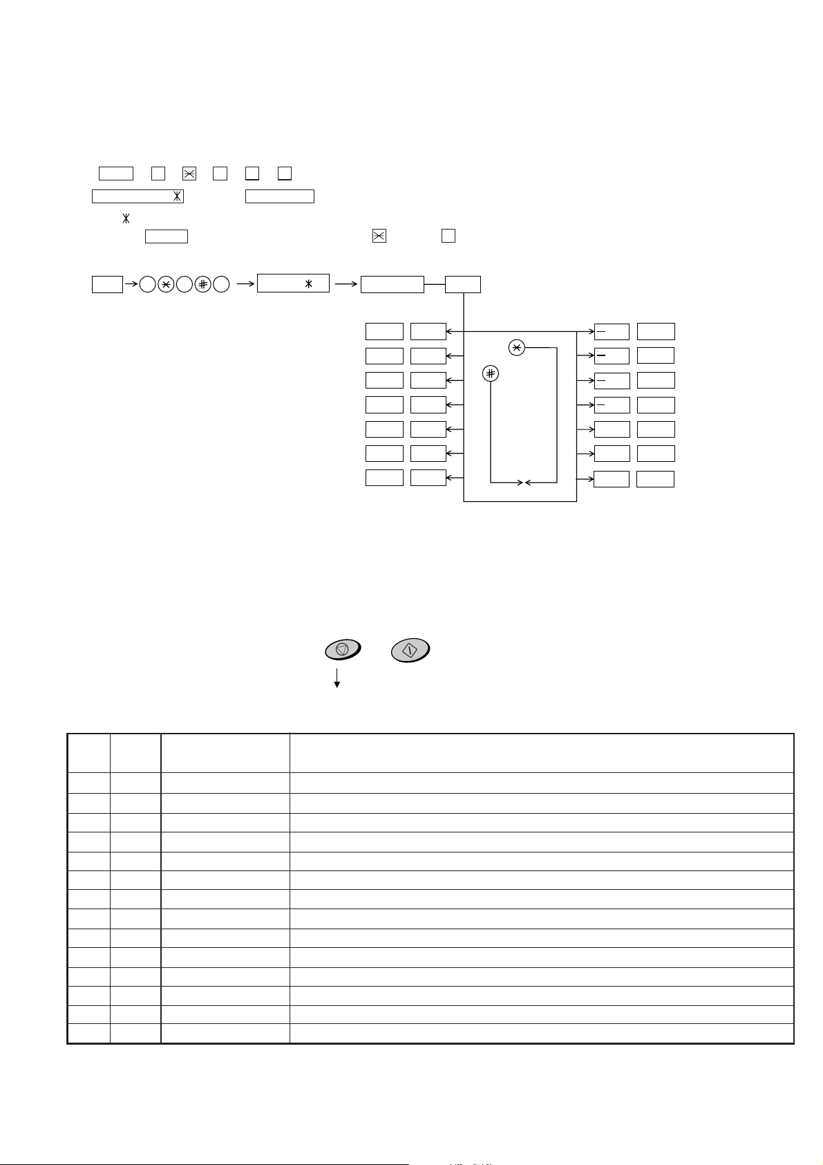
[5] Quick reference guide
FUNCTION key menu
The following chart shows the layout of the functions and settings accessed by pressing the FUNCTION key. First press the FUNCTION key, the
appropriate numeric key as shown, and then "#" or "
" until the desired item appears.
Instructions for making each setting appear in the display. If you have any dif ficulty , refer to the detailed instructions on the page shown below the setting.
Note: Steps which are optional are enclosed in a dotted frame:
Timer Mode
Send Mode
Polling Mode
Listing Mode
Timer List
Telephone
Number List
Passcode List
Option Setting
List
Anti Junk Fax
Number List
Answering
Machine
Program List
Message List
Entry Mode
Fax/Tel Numbers
for Auto Dialing
Own Number and
Name Set
Polling Security
Select
Passcode List
Date and Time Set
Anti Junk Number
Set
Optional Settings
Fine Resolution
Priority
Number of Rings
To Answer
5 Rings TEL
Answer
Recall Interval
Recall Times
Telephone/Fax
Remote Number
Remote Reception
Select
Transaction Report
Print Select
Dial Mode
Pseudo Ringing
Duration
Page Save
Time Save
Fax Signal Receive
Junk Number Check
Polling
1
2
3
4
FUNCTION
0
A.M. Settings
OGM Recording
Toll Saver
ICM Record
Time
Remote Code
Override Code
Transfer
Telephone
Number
Transfer
Function
Fax Box
ICM
Confirmation
On A.M. Failure
Box Passcode
Load
document
Lift handset
or
press
SPEAKER
Dial (press
numeric keys)
Wait for
reception tone
Hang up
Load
document
Load
document
Load
document
Load
document
Dial (press
numeric keys)
Press Rapid
key
Wait for
reception tone
Enter Speed Dial
number (press 2
numeric keys)
Normal Dialing
Direct Keypad
Dialing
Rapid Key Dialing
Speed Dialing
Redialing
Transmitting documents
REDIAL
SPEED DIAL
RESOLUTION
RESOLUTION
RESOLUTION
RESOLUTION
RESOLUTION
START/MEMORY
START/MEMORY
START/MEMORY
START/MEMORY
Recording an
outgoing message
Listening to
received messages
Erasing received
messages
Using the answering machine
0
FUNCTION
Press a number key
to select a box:
"0": General Box
"1": Box 1
"2": Box 2
"3": Box 3
"4": Transfer outgoing
message
Pick up the handset,
press the
START/MEMORY
key, and then speak
into the handset.
When finished,
replace the
handset or
press the
STOP key.
For a personal
box, enter the box
number
Enter passcode
if necessary
General messages
(no passcode):
Hold down DELETE
key for 2 seconds.
General messages
(passcode needed):
Press DELETE and
enter passcode.
General messages:
Press DELETE , enter
box number, and enter
passcode if necessary.
PLAY/SKIP
START/MEMORY
UX-258TH
FO-475TH
CHAPTER 2. ADJUSTMENTS
[1] Adjustments
General
Since the following adjustments and settings are provided for this model,
make adjustments and/or setup as necessary.
1. Adjustments
Adjustments of output voltage (FACTORY ONLY)
1. Install the power supply unit in the machine.
2. Set the recording paper and document.
3. When the document is loaded, power is supplied to the output lines.
Confirm that outputs are within the limits below.
Output voltage settings
(1) FU100 (ICP-S07) is installed in order to protect IC’s from an over-
current generated in the motor drive circuit. If FU100 is open, replace
it with a new one.
3. Settings
(1) Dial mode selector
DIAL mode (Soft Switch No. SWB4 DATA No. 3)
Output Voltage limits
+5V 4.75V ∼ 5.25V
+24V 23.3V ∼ 24.7V
2. IC protectors replacement
ICPs (IC Protectors) are installed to protect the motor driver circuit.
ICPs protect various ICs and electronic circuits from an overcurrent con-
dition.
The location of ICPs are shown below:
1DG
2 +5V
3 VTH-ON
4MG
5MG
6MG
7 +24V
8 VTH
9 VTH
10 VTH
Connector
No. CNPW
Pin No.
2 – 1
TEL/LIU PWB
POWER SUPPLY PWB
CNLIU
CNLIUA
CN2
CNPW
CONTROL PWB
CONTROL PWB
(TOP SIDE)
CNLIUA
CNPW
FU100
4. Method of release of starting lock up by Battery
Reset
(1) Summary
There is a possibility of release of the lock up by reset the signal BA TRST
of CPU (FC100), if it lock up when you turn on the power of the set in
UX-258 series. We inform you of the method of release.
(2) Contents
When you turn on the power of the set without EPROM by your mistake,
if you turn off the power after , turn on the power with EPROM again, the
set don’t start.
In this case, before you judge the cpu (FC100) is wrong, you need to
confirm the release of the lock up by reset the signal BATRST. and
unknown origin in the same way.
Method of the reset of signal BATRST
Short the between leads of the capacitor C5 on the control PWB,
X2961-81 in the state of POWER OFF.
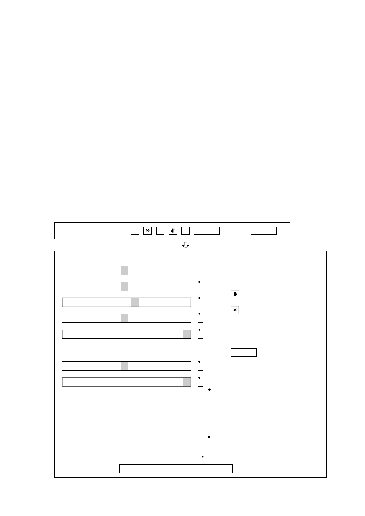
(step 1) Select "OPTION SETTING".
KEY : FUNCTION 4
DISPLAY: OPTION SETTING PRESS OR #
(step 2) Select "DIAL MODE".
KEY:
DISPLAY: DIAL MODE 1=TONE, 2=PULSE
(step 3) Select, using "1" or "2".
KEY: 1
DISPLAY: TONE SELECTED
KEY: 2
DISPLAY: PULSE SELECTED
(step 4) End, using the "STOP" key.
KEY:
Cursor
When initially registering,
the mode shows 1=TONE.
When registering again, the
mode which was registered
formerly is shown.
STOP
#
#
#
# #
# #
#
#
UX-258TH
FO-475TH
[2] Diagnostics and service soft switch
1. Operating procedure
(1) Entering the diagnostic mode
Press FUNC → 9 → → 8 → # → 7 , and the following display will appear.
ROM Ver. FKD0 After 2 sec: DIAG MODE
FKD0
Then press the STAR T key. Select the desired item with the key or the # key or select with the rapid key. Enter the mode with the START key.
(Diag•specifications)
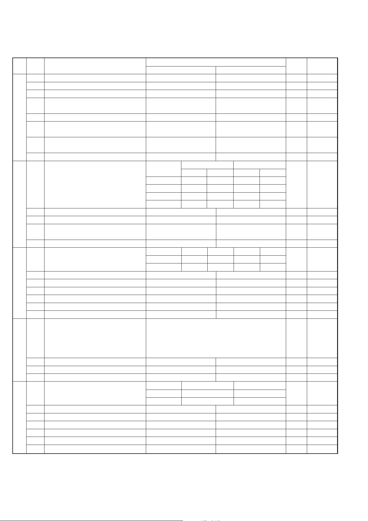
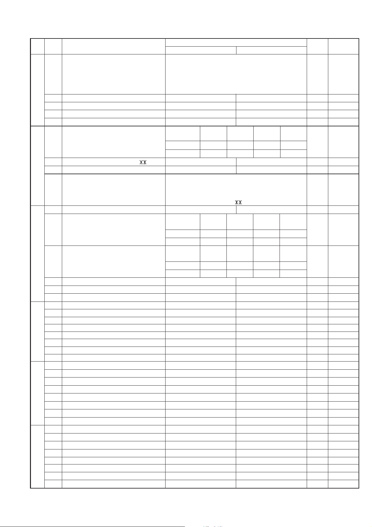
2. Diagnostic items
ITEM DIRECT
Contents Function
No. key
1 1 SOFT SWITCH MODE Soft switches are displayed and changed. List can be output.
2 2 ROM & RAM CHECK ROM is sum-checked, and RAM is matched. Result list is output.
3 3 AGING MODE 10 sheets of check patterns are output every 5 minutes per sheet.
4 4 PANEL KEY TEST Panel keys are tested. Result list is output.
55
CHECK PATTERN MODE
Check pattern is output.
6 6 SIGNAL SEND MODE Various signals of FAX communication are output.
77
MEMORY CLEAR MODE
Back-up memory is cleared, and is set at delivery.
8 8 SHADING MODE Shading compensation is performed in this mode.
9 9 ALL BLACK MODE To check the print head, whole dots are printed over the interval of 2 m.
10 10 AUTO FEEDER MODE Insertion and discharge of document are tested.
11 − ENTRY DATA SEND Registered content is sent.
12 − ENTRY DATA RECEIVE Registered content is received, and its list is output.
13 −
FLASH MEMORY CHECK
Flash memory is checked.
14 −
FLASH MEMORY CLEAR
Data of flash memory is cleared.
If the diag mode cannot be set, repeat the diag mode operation, per-
forming the following operation.
After the power is turned on and "ESPERE POR FAVOR" is indicated,
press the STOP key.
2 – 2
In relation with the process response (request from Production
Engineering) "ESPERE POR FAVOR" clock indication may
appear depending on STOP key timing. If the STOP key is
held down, "MEMORY CLEAR?" appears.
FUNC
DIAG MODE
9 8 7
START 1Soft switch mode
START
2ROM & RAM check
START
3Aging mode
START
4Panel key test
START
5Check pattern mode
START 6Signal send mode
START
7Memory clear mode
All black mode
START
Auto feeder mode
START
Entry data send
START
10
Entry data receive
START
START9
START
KEY
STOP
KEY
+
+
"Power ON"
Memory clear
(Work + Backup)
FKD0
START Flash memory check
START
Flash memory clear
Shading mode
START
8

UX-258TH
FO-475TH
3. Diagnostic items description
3. 1. Soft switch mode
Used to change the soft switch settings.
The soft switch which is stored internally is set by using the keys.
The available soft switches are SW-A1 to SW-L2.
The content of soft switches is shown in page 2-5 to 2-16.
The contents are set to factory default settings.
3. 2. ROM & RAM check
ROM executes the sum check, and RAM executes the matching test.
The result will be notified with the number of short sounds of the buzzer
as well as by printing the ROM & RAM check list.
Number of short sounds of buzzer 0 → No error
1 → ROM error
2 → RAM error (32Kbyte)
3. 3. Aging mode
If any document is first present, copying will be executed sheet by sheet.
If no document is present, the check pattern will be printed sheet by
sheet. This operation will be executed at a rate of one sheet per 5min-
utes, and will be ended at a total of 10 sheets.
3. 4. Panel key test
The mode is used to check whether each key operates properly
or not. Press the key on the operation panel, and the key will be dis-
played on the display. Therefore, press all keys. At this time, finally press
the STOP key.
When the STOP key is pressed, the keys which are not judged as
"pressed" will be printed on the result list.
• LED port of the contact image sensor (CIS) is kept on during the
term from when start of the panel test mode to end with the STOP
key.
3. 5. Check pattern mode
This mode is used to check the status of print head. Two sheets of check
pattern are printed. The following information of check pattern is printed.
1
Vertical stripes
(alternate white and black lines)
Approx. 35 mm
2
Full black Approx. 70 mm
3
Full white Approx. 35 mm
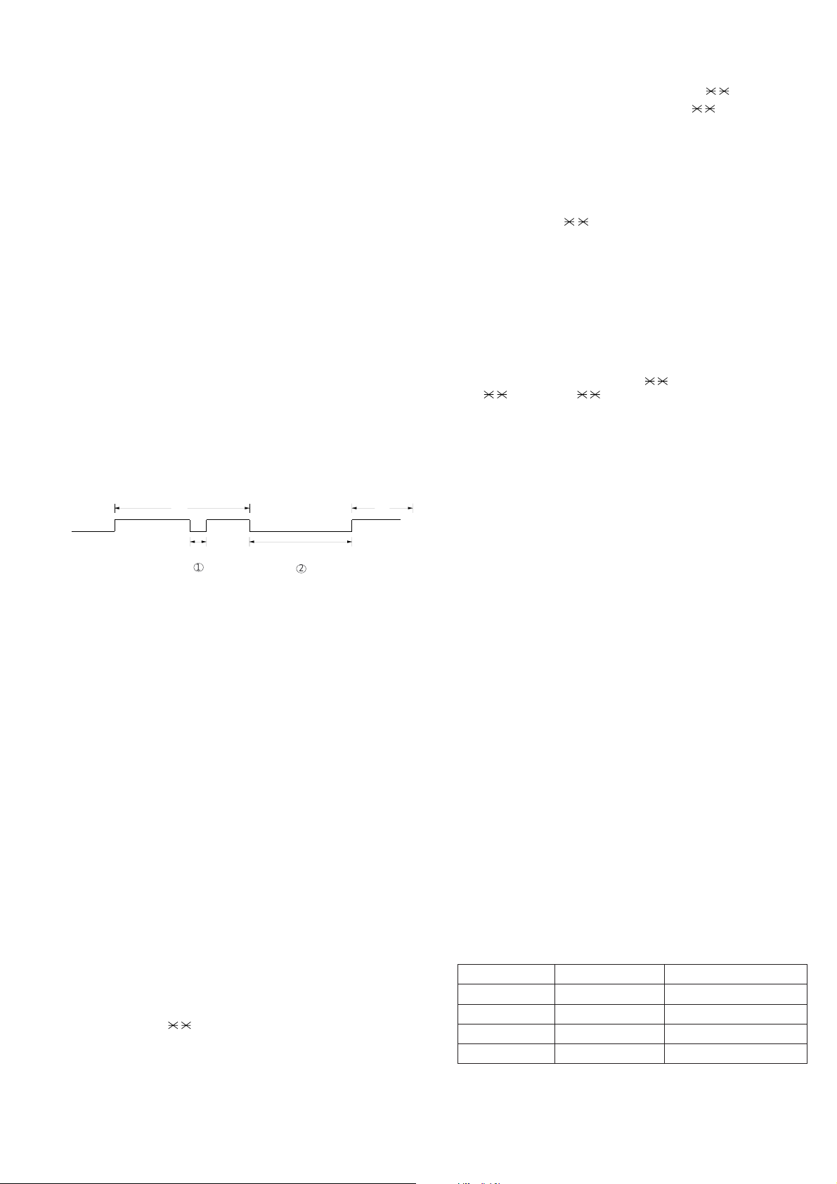
3. 6. Signal send mode
The mode is used to send various signals to the circuit during FAX com-
munication. Every push of START key sends a signal in the following
sequence. Moreover, the signal sound is also output to the speaker when
the line monitor of the soft switch is on.
[1] No signal (CML signal turned on)
[2] 9600bps
[3] 7200bps
[4] 4800bps
[5] 2400bps
[6] 300bps (FLAG)
[7] 2100Hz (CED)
[8] 1100Hz (CNG)
[9] END
3. 7. Memory clear mode
This mode is used to clear the backup memory and reset to the default
settings.
3. 8. Shading mode
The mode is used for the shooting compensation. For reading, set up
the special original paper.
The shooting compensation memorizes the reference data of white and
black for reading.
Moreover, the memorized data is not erased even if memory clear mode
is executed.
3. 9. All black mode
The mode is used to check the state of the printing head and inten-
tionally overheat it. Whole dots are printed over the interval of 2 m. If it is
overheated or the printing sheet is jammed, press STOP key for the end.
3. 10. Auto feeder mode
In this mode, a document is inserted and discharged to check the auto
feed function.
After this mode is started, set a document, and the document feed will
be automatically tested.
3. 11. Entry data send
The mode is used to send the registered data to the other machine and
make the other machine copy the registered content.
Before sending in this mode, it is necessary to set the other machine at
the entry data receive mode.
The sent content is as follows. After printing is completed, the following
lists are printed.
1. Telephone list data
2. Sender register data
3. Optional setting content
4. Soft switch content
5. Junk fax number list
6. Timer reservation data (only on the model which timer reserva-
tion is possible)
7. Recording setting list data
2 – 3
1
2
3
RANK 0 or 1
Note:
There is a selection RANK 0 or 1 depending on resistance value of the
thermal head. RANK 0 or RANK 1 is printed at the tail of check pattern
to identify.
UX-258TH
FO-475TH
3. 12. Entry data receive
In this mode, the registered data sent from the other machine are re-
ceived and the received data are registered in the own machine. When
this mode is used for receiving, the other machine must be in the entry
data send mode.
After receiving is completed, the following lists are printed.
1. Telephone list data
2. Sender register data (The passcode No. is also printed if the poling
function is provided.)
3. Optional setting list
4. Soft switch content
5. Junk fax number list
6. Timer reservation list (only model which timer communication is
possible)
7. Recording setting list data
2 – 4
3. 13. Flash memory check
Data writing/read of flash memory is checked, and the result (OK/NG) is
printed.
3. 14. Flash memory clear
All data of flash memory is cleared.
The result of clear (OK/NG) is printed.
Press
FUNCTION
9 8 7 START START
Press FUNCTION key.
Press key.
Press key.
Bit1 - 8 are set.
Soft SW-A2 - SW-L2 are set.
S F T SW-A1 = 1 0 0 0 0 0 0 0
S F T SW-A1 = 1 0 0 0 0 0 0 0
S F T SW-A1 = 1 0 0 0 0 0 0 0
S F T SW-A1 = 1 0 0 0 0 0 0 0
S F T SW-A2 = 0 0 0 0 0 0 0 0
S F T SW-L2 = 0 0 0 0 0 0 0 0
Press key during setting.
To finish the settings halfway between
SW-A1 and SW-L2, press the STOP
key. In this case, the setting being done
to the SW No. on display will be nullified
while settings done to the preceding
SW Nos. remain in effect.
The soft switch mode is terminated.
S F T SW-A1 = 0 0 0 0 0 0 0 0
START
DATA No. 1 2 3 4 5 6 7 8
When the COPY key is pressed, the
contents of soft switches are printed.
4. How to make soft switch setting
T o enter the soft switch mode, make the following key entries in sequence.
UX-258TH
FO-475TH
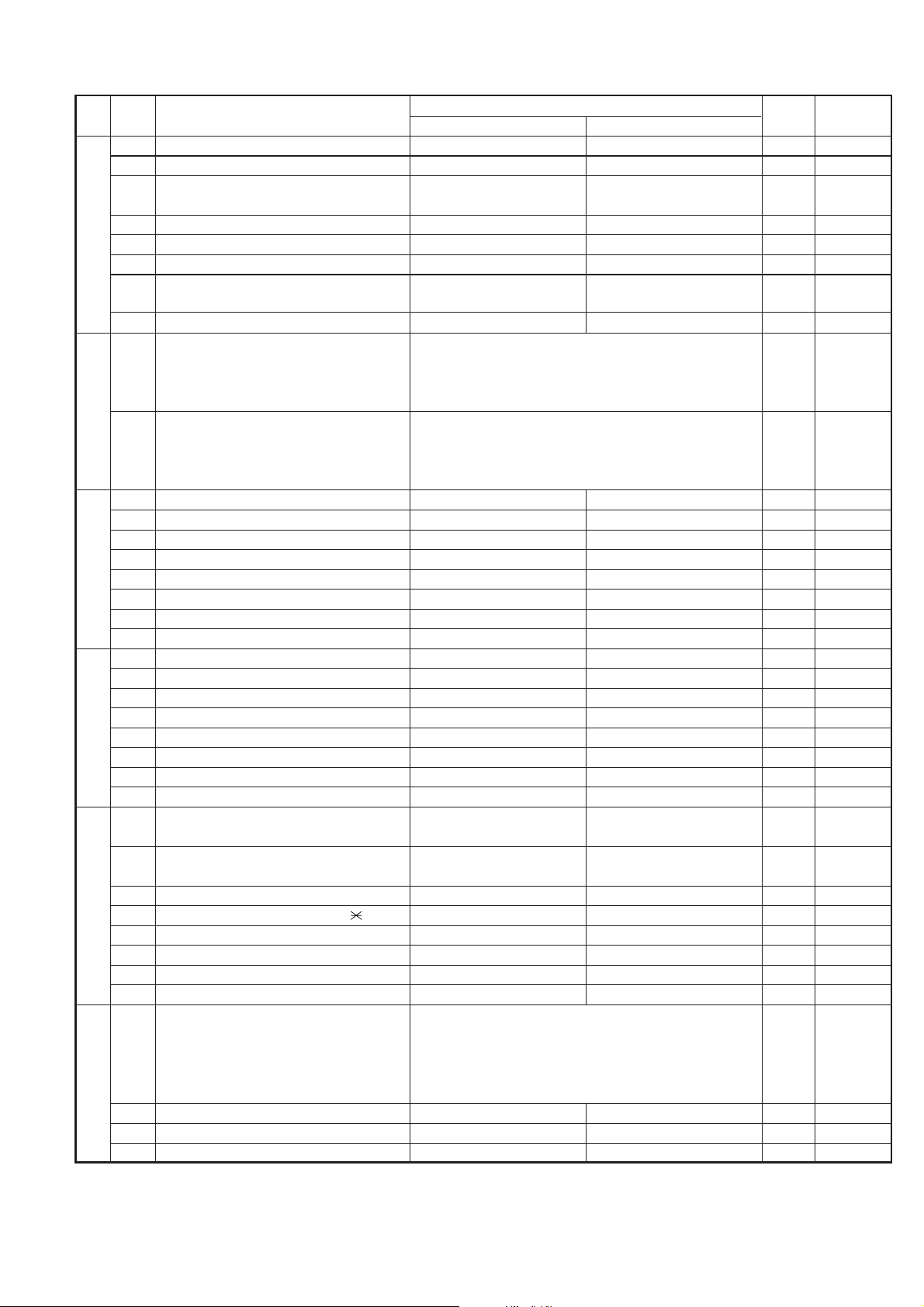
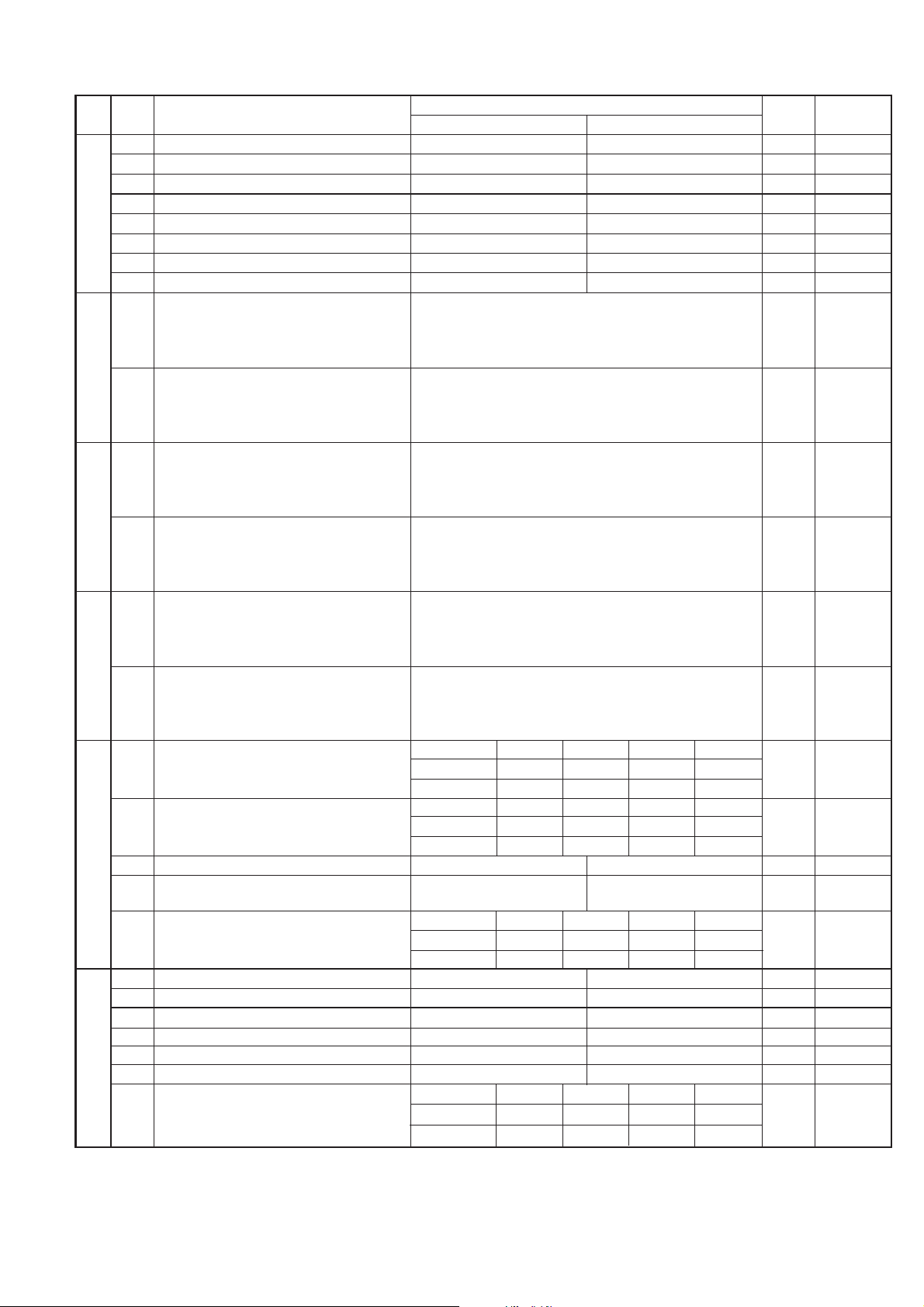
5. Soft switch description
• Soft switch
1 Protect from echo No Yes 0
2 Forced 4800 BPS reception Yes No 0
3 Footer print Yes No 0
4 Length limitation of copy/send/receive No limit Copy/send: 60cm 0
Receive: 1.5m
5 CSI transmission No transmitted Transmitted 0
6 DIS receive acknowledgement during G3 Twice NSF: Once 0
transmission DIS: Twice
7 Non-modulated carrier for V29 transmission Yes No 0
modem
8 EOL detect timer 25 s 13 s 0
Modem speed V.29 V.27 ter
9600bps 7200bps 4800bps 2400bps
1 No. 1 0 0 0 0 0
2 No. 2 0 0 0 0 0
3 No. 3 0 1 1 0 0
4 No. 4 1 1 0 0 1
5 Sender’s information transmit No Yes 0
6 H2 mode No Yes 0
7 Communication error treatment in RTN No communication error Communication error 0
sending mode (reception)
8 CNG transmission No Yes 0
CED tone signal interval 1000ms 750ms 500ms 75ms
1 No. 1 1 1 0 0 0
2 No. 2 1 0 1 0 0
3 MR coding No Yes 0
4 Reserved 0
5 Reserved 0
6 Reserved 0
7 Reserved 0
8 Reserved 0
1 Signal transmission level Binary input 0
2 No. = 16 8 4 2 1 0
3 1 2 3 4 5 1
4 0 0 1 0 0 (-8 dBm) 0
5 0
6 Protocol monitor (error print) Printed at com. err Not printed 0
7 Protocol monitor Yes No 0
8 Line monitor Yes No 0
Digital line equalization setting (Reception) 7.2km 0km
1 No. 1 1 0 1
2 No. 2 1 0 1
3 Reserved 0
4 Reserved 0
5 Reserved 0
6 Reserved 0
7 Error criterion 10 ~ 20 % 5 ~ 10 % 0
8 Anti junk fax check Yes No 0 OPTION
SW
NO.
DAT A
NO.
ITEM
Switch setting and function
10
Remarks
Initial
setting
SW
l
A1
SW
l
A2
SW
l
A3
SW
l
A5
SW
l
A4
2 – 5
UX-258TH
FO-475TH
1 Auto gain control (MODEM) Enable Disable 1
2 End Buzzer Yes No 1
3 Disconnect the line when DIS is received in No Ye s 1
RX mode
4 Equalizer freeze control (MODEM) On Off 0
5 Equalizer freeze control 7200 BPS only No Yes 0
6 CNG transmission in manual TX mode Yes No 1
7 Initial compression scheme for sharp fax in MR mode H2 mode 0
TX mode
8 Reserved 0
1 Recall interval Binary input 0 OPTION
2 No. = 8 4 2 1 1
3 1 2 3 4 0
4 0 1 0 1 (5 x 60 sec = 5 min) 1
5 Recall times Binary input 0 OPTION
6 No. = 8 4 2 1 0
7 5 6 7 8 1
8 0 0 1 0 (Twice) 0
1 Dial pausing (sec/pause) 4 sec 2 sec 0
2 Reserved 0
3 Reserved 0
4 Busy tone detection (after auto dial) No Yes 1
5 Waiting time after dialing 90 sec 45 sec 0
6 Reserved 0
7 Reserved 0
8 Reserved 0
1 Reserved 0
2 Reserved 0
3 Reserved 0
4 Reserved 0
5 Reserved 0
6 Reserved 0
7 Reserved 0
8 Hold function Enable Disable 1
1 Auto Dial Mode Delay timer of before line 3 sec 0 sec 1
connect
2 Auto Dial Mode Delay timer of after line 3.6 sec 3 sec 0
connect
3 Dial mode Tone Pulse 1 OPTION
4 Pulse → Tone change function by
key Enable Disable 1
5 Dial pulse make/break ratio (%) 40/60 33/67 1
6 Reserved 0
7 Reserved 0
8 Reserved 0
1 DTMF signal transmission level (Low) Binary input 0
2 No. = 16 8 4 2 1 1
3 1 2 3 4 5 0
4 0 1 0 1 0 (0.5 x 12 = -6 dBm) 1
5 0
6 Reserved 0
7 Reserved 0
8 Reserved 0
SW
NO.
DA T A
NO.
ITEM
Switch setting and function
1
0
Remarks
Initial
setting
SW
l
B5
SW
l
B4
SW
l
B3
SW
l
B2
SW
l
B1
SW
l
A6
2 – 6
UX-258TH
FO-475TH
1 DTMF signal transmission level (High) Binary input 0
2 No. = 16 8 4 2 1 0
3 1 2 3 4 5 1
4 0 0 1 1 0 (0.5 x 7 = -3.5 dBm) 1
5 0
6 Reserved 0
7 Reserved 0
8 Reserved 0
Reading slice (Binary) Factory Light Dark Darker in
setting dark mode
1 No. 1 0 1 0 1 0
2 No. 2 0 0 1 1 0
Reading slice (Half tone) Factory Light Dark Darker in
setting dark mode
3 No. 3 0 1 0 1 0
4 No. 4 0 0 1 1 0
5 Line density selection Fine Standard 0 OPTION
6 Reserved 0
7 MTF correction in half tone mode No Yes 0
8 Reserved 0
1 Number of rings for auto receive Binary input 0 OPTION
2 No. = 8 4 2 1 0
3 1 2 3 4 0
4 0 0 0 1 (4 times) 1
5 Automatic switching manual to auto receive Reception after 5 rings No reception 0 OPTION
mode
6 Reserved 0
7 Reserved 0
8 Reserved 0
1 Reserved 0
2 Reserved 0
3 Reserved 0
4 Reserved 0
5 Reserved 0
CI off detection timer (Distinctive ring 1200ms 1000ms 700ms 350ms
6 setting off only) No. 6 0 1 0 1 0
7 No. 7 0 0 1 1 1
8 Reserved 0
1 Tel/Fax Automatic switching mode Enable Disable 0
Pseudo ringing time at phone/fax automatic 15sec 60sec 30sec 120sec OPTION
2 switching mode No. 2 0 0 1 1 0
3 No. 3 0 1 0 1 0
4 Number of CNG signal detection at the Twice Once 1
phone/fax automatic switching mode
5 CNG detect time at TEL/FAX mode 3 sec 5 sec 0
6 Reserved 0
7 Reserved 0
8 Reserved 0
2 – 7
SW
NO.
DATA
NO.
ITEM
Switch setting and function
1
0
Remarks
Initial
setting
SW
l
B6
SW
l
C1
SW
l
D2
SW
l
D1
SW
l
E1
UX-258TH
FO-475TH
DA T A
NO.
1 Pseudo ringer sound output level to the line Binary input 0
2 No. = 8 4 2 1 1
3 1 2 3 4 0
4 0 1 0 1 (-5 dBm -5 = -10 dBm) 1
(-5 ~ -20 dBm setting)
5 Reserved 0
6 Reserved 0
7 Reserved 0
8 Reserved 0
DTMF detection time 50ms 80ms 100ms 120ms
1 No. 1 0 0 1 1 0
2 No. 2 0 1 0 1 0
3 Protection of remote reception (5
) detect Yes No 0 OPTION
4 Remote reception with GE telephone Compatible Not compatible 1
5 Remote operation code figures by external Binary input 0 OPTION
6 TEL (0~9) No. = 8 4 2 1 1
7 5 6 7 8 0
8 0 1 0 1 (5
)1
1 CNG detection in STAND-BY mode Yes No 1 OPTION
Number of CNG detect (AM mode) 1pulse 2pulses 3pulses 4pulses
2 No. 2 0 0 1 1 0
3 No. 3 0 1 0 1 1
Number of CNG (STAND-BY mode) 1pulse 2pulses 3pulses 4pulses
4 No. 4 0 0 1 1 0
5 No. 5 0 1 0 1 1
6
Fax signal detection after telephone mode dial
Yes No 0
7 Reserved 0
8 Reserved 0
1 Reserved 0
2 Reserved 0
3 Reserved 0
4 Reserved 0
5 Reserved 0
6 Reserved 0
7 Reserved 0
8 Reserved 0
1 Reserved 0
2 Reserved 0
3 Reserved 0
4 Reserved 0
5 Reserved 0
6 Reserved 0
7 Reserved 0
8 Reserved 0
1 Reserved 0
2 Reserved 0
3 Reserved 0
4 Reserved 0
5 Reserved 0
6 Reserved 0
7 Reserved 0
8 Reserved 0
SW
l
F1
SW
l
E2
SW
l
F2
SW
l
G1
SW
l
G2
SW
l
G3
SW
NO.
ITEM
Switch setting and function
1
0
Remarks
Initial
setting
2 – 8

UX-258TH
FO-475TH
1 Busy tone detection ON/OFF time (Lower 350ms 150ms 0
duration)
2 Busy tone detection ON/OFF time (Upper 650ms 900ms 0
duration)
3 Reserved 0
4 Busy tone continuous sound detect time 5s 10s 1
5 Busy tone detect continuation sound detect No Yes 0
during OGM
6 Busy tone detect continuation sound detect No Yes 0
during ICM
7 Busy tone detect intermittent sound detect No Yes 0
during OGM
8 Busy tone detect intermittent sound detect No Yes 0
during ICM
Busy tone detection pulse number 2pulses 4pulses 6pulses 10pulses
1 No. 1 0 0 1 1 0
2 No. 2 0 1 0 1 1
3 Fax switching when A.M. full Y e s No 0 OPTION
4 Busy tone detect continuation sound detect 320 - 570 Hz 320 - 460 Hz 0
frequency
5 Reserved 0
6 Reserved 0
7 Reserved 0
8 Reserved 0
ICM recording time 4min 15s 30s 60s OPTION
1 No. 1 0 0 1 1 0
2 No. 2 0 1 0 1 0
A.M. quiet time 1 2S 3s 4s 5s
3 No. 3 0 0 1 1 0
4 No. 4 0 1 0 1 0
A.M. quiet time 2 0s 1s 2s 3s
5 No. 5 0 0 1 1 1
6 No. 6 0 1 0 1 0
7 Key input buzzer on/off switch (Two way On Off 0
recording mode)
8 Reserved 0
1 A.M. quiet detect time Binary input 0
2 No. = 16 8 4 2 1 0
3 1 2 3 4 5 1
4 0 0 1 1 0 (6 sec) 1
5 0
6 Reserved 0
7 Reserved 0
8 Alarm during two way recording Yes No 0
SW
l
H1
SW
NO.
DATA
NO.
ITEM
Switch setting and function
1
0
Remarks
Initial
setting
SW
l
H2
SW
l
I1
SW
l
I2
2 – 9
UX-258TH
FO-475TH
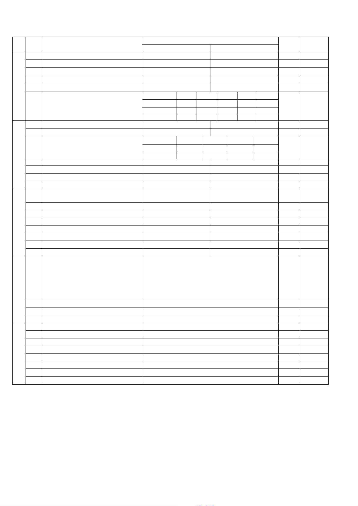
1 Max OGM record time 15s 60s 0
2 Reserved 0
3 Two way record function Disable Enable 0
4 Toll saver Disable Enable 0 OPTION
5 Reserved 0
6 Reserved 0
7 BOX selection to record ICM 2 digits DTMF 1digit DTMF 0
8 Transfer did recall Disable Enable 0
1 AGC maximum gain (line) Binary input 1
2 (10 ~ 25 dBm ) No. = 8 4 2 1 1
3 1 2 3 4 0
4 1 1 0 1 (23 dB) 1
5 AGC maximum gain (Mic) Binary input 0
6 (10 ~ 25 dBm ) No. = 8 4 2 1 0
7 5 6 7 8 1
8 0 0 1 0 (12 dB) 0
1 AGC eref access code (line) Binary input 0
2 (-0 ~ -30 dBm with 2 dBm step) No. = 8 4 2 1 1
3 1 2 3 4 1
4 0 1 1 1 (-14 dB) 1
5 AGC eref access code (Mic) Binary input 1
6 (-0 ~ -30 dBm with 2 dBm step) No. = 8 4 2 1 0
7 5 6 7 8 0
8 1 0 0 1 (-18 dB) 1
1 AGC again adaptation threshold (line) Binary input 1
2 (-40 ~ -70 dBm with 2 dBm step) No. = 8 4 2 1 1
3 1 2 3 4 1
4 1 1 1 1 (-70 dB) 1
5 AGC again adaptation threshold (Mic) Binary input 0
6 (-40 ~ -70 dBm with 2 dBm step) No. = 8 4 2 1 1
7 5 6 7 8 0
8 0 1 0 1 (-50 dB) 1
AGC slew rate (line) Slow Normal Little fast Fast
1 No. 1 0 0 1 1 0
2 No. 2 0 1 0 1 1
AGC slew rate (Mic) Slow Normal Little fast Fast
3 No. 3 0 0 1 1 1
4 No. 4 0 1 0 1 1
5 FAX BOX function Disable Enable 0 OPTION
6 Frequency of voice detection after 800 Hz ~ 1400 Hz 800 Hz ~ 1200 Hz 0
REMINDER dialing
Voice detection time after REMINDER dialing
100ms 200ms 300ms 400ms
7 No. 7 0 0 1 1 0
8 No. 8 0 1 0 1 0
1 Reserved 0
2 Reserved 0
3 Sender’s phone number setting Cannot change Change allowed 0
4 Reserved 0
5 Reserved 0
6 Reserved 0
Ringer volume Off Low Middle High OPTION
7 No. 7 0 0 1 1 1
8 No. 8 0 1 0 1 0
SW
l
I3
SW
l
I4
SW
l
I5
SW
l
I6
SW
l
J1
SW
NO.
DA TA
NO.
ITEM
Switch setting and function
1
0
Remarks
Initial
setting
2 – 10
SW
l
I7
UX-258TH
FO-475TH
1 Reserved 0
2 Reserved 0
3 Polling key Y es NO 0 OPTION
4 Reserved 0
5 Reserved 0
Speaker volume (5 stages)
Very Low
Low Middle High
Very High
OPTION
6 No. 6 0 0 0 0 1 0
7 No. 7 0 0 1 1 0 1
8 No. 8 0 1 0 1 0 0
1 Reserved 0
2 Reserved 0
Communication results printout Error/Timer Send only Always No print OPTION
3 (Transaction report) No. 3 0 0 1 1 0
4 No. 4 0 1 0 1 0
5 Reserved 0
6 Reserved 0
7 Reserved 0
8 Reserved 0
1 Entering DIAG mode by pressing SPEED Yes No 0
key
2 Reserved 0
3 Reserved 0
4 Reserved 0
5 Reserved 0
6 Reserved 0
7 Reserved 0
8 Reserved 0
OGM / ICM output level Binary input
1 No. = 16 8 4 2 1 1
2 1 2 3 4 5 0
3 1 0 0 0 1 (-17 dBm) 0
4 0
5 1
6 Reserved 0
7 Reserved 0
8 Reserved 0
1 Reserved 0
2 Reserved 0
3 Reserved 0
4 Reserved 0
5 Reserved 0
6 Reserved 0
7 Reserved 0
8 Reserved 0
SW
l
K1
SW
l
L1
SW
l
L2
SW
NO.
DATA
NO.
ITEM
Switch setting and function
1
0
Remarks
Initial
setting
2 – 11
SW
l
J2
SW
l
J3

UX-258TH
FO-475TH
• Soft switch function description
SW-A1 No. 1 Protect from echo
Used to protect from echo in reception.
SW-A1 No. 2 Forced 4800BPS reception
When line conditions warrant that receptions take place at 4800 BPS
repeatedly.
It may improve the success of receptions by setting at 4800BPS.
This improve the receiving document quality and reduces handshake
time due to fallback during training.
SW-A1 No. 3 Footer print
When set to "1", the date of reception, the sender machine No., and the
page No. are automatically recorded at the end of reception.
SW-A1 No. 4 Length limitation of copy/send/receive
Used to set the maximum page length.
To avoid possible paper jam, the page length is normally limited to 0.6
meter for copy or transmit, and 1.5 meters for receive.
It is possible to set it to "No limit" to transmit a long document, such as a
computer print form, etc. (In this case, the receiver must also be set to
no limit.)
SW-A1 No. 5 CSI transmission
(CSI TRANSMISSION) is a switch to set whether the machine sends or
does not send the signal (CSI signal) informing its own telephone No. to
the remote fax. machine when information is received. When
"nonsending" is set, the telephone No. is not output on the remote trans-
mitting machine if the remote transmitting machine has the function to
display or print the telephone No. of receiving machine, using this CSI
signal.
SW-A1 No. 6 DIS receive acknowledgment during G3 transmission
Used to make a choice of whether reception of DIS (NSF) is acknowl-
edged after receiving two DISs (NSFs) or receiving one DIS (two NSFs).
It may be useful for overseas communication to avoid an echo sup-
pression problem, if set to 1.
SW-A1 No. 7 Non-modulated carrier for V29 transmission modem
Though transmission of a non-modulated carrier is not required for trans-
mission by the V29 modem according to the CCITT recommendation, it
may be permitted to a send non-modulated carrier before the image
signal to avoid and echo suppression problem. It may be useful for over-
seas communication to avoid an echo suppression problem, if set to 1.
SW-A1 No. 8 EOL (End Of Line) detect timer
Used to make a choice of whether to use the 25-second or 13-second
timer for detection of EOL.
This is effective to override communication failures with some facsimile
models that have longer EOL detection.
SW-A2 No. 1 ~ No. 4 Modem speed
Used to set determine the initial modem speed. The default is 9600BPS.
It may be necessary to program it to a slower speed when frequent line
fallback is encountered, in order to save the time required for fallback
procedure.
SW-A2 No. 5 Sender’s information transmit
(SENDER’S INFORMATION TRANSMISSION) is a switch to set the
function to print the content of HEADER PRINT described in the passcode
list at the front end of receiver’s original when original is sent to the
remote machine.
If this switch is set to "NO", the HEADER PRINT is not output at the
receiving machine.
SW-A2 No. 6 H2 mode
Used to determine reception of H2 mode (15 sec transmission mode).
When set to OFF , H2 mode reception is inhibited even though the trans-
mitting machine has H2 mode function.
SW-A2 No. 7 Communication error treatment in RTN sending mode
(Reception)
Used to determine communication error treatment when RTN is sent by
occurrence of a received image error in G3 reception. When it is set to
"1", communication error is judged as no error.
SW-A2 No. 8 CNG transmission
When set to "0" , this model allows CNG transmission by pressing the
Start key in the key pad dialing mode. When set to "1", CNG transmis-
sion in the key pad dialing mode cannot be performed. In either case,
CNG transmission can be performed in the auto dial mode.
SW-A3 No. 1, No. 2 CED tone signal interval
For international communication, the 2100Hz CED tone may act as an
echo suppression switch, causing a communication problem.
Though SW-A3 No. 1 and No. 2 are normally set to 0, it should be changed
this time between the CED tone signal to eliminate the communication
problem caused by echo.
SW-A3 No. 3 MR Coding
Used to select the MR coding enable or disable.
SW-A3 No. 4 ~ No. 8 Reserved
Set to "0".
SW-A4 No. 1 ~ No. 5 Signal transmission level
Used to control the signal transmission level in the range of-0dB to-
31dB.
The factory setting is at
-8dB (MODEM output).
SW-A4 No. 6 Protocol monitor (Error print)
If set to "1", protocol is printed at communication error.
SW-A4 No. 7 Protocol monitor
Normally set to "0". If set to "1", communication can be checked, in case
of troubles, without using a G3 tester or other tools.
When communication FSK data transmission or reception is made, the
data is taken into the buffer . When communication is finished, the data is
analyzed and printed out. When data is received with the line monitor
(SW-A4 No. 8) set to "1" the reception level is also printed out.
SW-A4 No. 8 Line monitor
Normally set to "0". If set to "1", the transmission speed and the recep-
tion level are displayed on the LCD. Used for line tests.
SW-A5 No. 1, No. 2 Digital line equalization setting (Reception)
Line equalization when reception is to be set according to the line char-
acteristics.
Setting should be made according to distance between the telephone
and the telephone company central switching station.
SW-A5 No. 3 ~ No. 6 Reserved
Set to "0".
SW-A5 No. 7 Error criterion
Used to select error criterion for sending back RTN when receiving im-
age data.
SW-A5 No. 8 Anti junk fax check
When use the Anti junk fax function, set to "1".
SW-A6 No. 1 Auto gain control (MODEM)
When this mode is enabled, if the reception signal level is under 31dBm.
The modem itself controls the signal gain automatically.
2 – 12
TX RX
CED
DIS
T

UX-258TH
FO-475TH
SW-A6 No. 2 End buzzer
Setting this bit to 0 will disable the end buzzer (including the error buzzer/
on-hook buzzer).
SW-A6 No. 3 Disconnect the line when DIS is received in RX mode
Bit1= 0: When DIS signal is received during RX mode, disconnected the
line is immediately.
Bit1= 1: When DIS signal is received during RX mode, wait the next
signal.
SW-A6 No. 4 Equalizer freeze control (MODEM)
This switch is used to perform reception operation by fixing the equal-
izer control of modem for the line which is always in unfavorable state
and picture cannot be received.
* Usually, the control is executed according to the state of line where
the equalizer setting is changed always.
SW-A6 No. 5 Equalizer freeze control 7200BPS only
Setting which specifies SW-A3 No. 6 control only in the condition of
7200BPS modem speed.
SW-A6 No. 6 CNG transmission in manual TX mode
When set to "1", fax transmit the CNG signal in case of manual trans-
mission mode (User press the STAR T key after waiting the fax answer-
ing signal from handset or speaker).
SW-A6 No. 7 Initial compression scheme for sharp fax in TX mode
When set to "0", if the other fax is Sharp model, fax transmit the docu-
ment by H2 mode. When set to "1", even if the other fax is Sharp model,
fax transmit the document by MR mode.
SW-A6 No. 8 Reserved
Set to "0".
SW-B1 No. 1 ~ No. 4 Recall interval
Choice is made for a redial interval for speed and rapid dial calls.
Used a binary number to program this. If set to 0 accidentally, 1 will be
assumed.
SW-B1 No. 5 ~ No. 8 Recall times
Choice is made as to how many redials should be.
SW-B2 No. 1 Dialing pause (sec/pause)
Pauses can be inserted between telephone numbers of direct dial con-
nection. Selection of 4 sec or 2 sec pause is available.
SW-B2 No. 2, No. 3 Reserved
Set to "0".
SW-B2 No. 4 Busy tone detection (after auto dial)
Used to set YES/NO of busy tone detection after auto dialing.
SW-B2 No. 5 Waiting time after dialing
This is waiting time for the opponent’s signals after dialing.
When set to "0", waiting time is 45 sec.
When set to "1", waiting time is 90 sec.
SW-B2 No. 6 ~ No. 8 Reserved
Set to "0".
SW-B3 No. 1 ~ No. 7 Reserved
Set to "0".
SW-B3 No. 8 Hold function
Used to set YES/NO of holding function by the HOLD key.
SW-B4 No. 1 Auto dial mode Delay timer of before line connect
Delay time between the dial key input and line connection under the
auto dial mode.
SW-B4 No. 2 Auto dial mode Delay timer of after line connect
Delay time between the line connection and dial data output under the
auto dial mode.
SW-B4 No. 3 Dial mode
When using the pulse dial, set to 0. When using the tone dial, set to 1.
SW-B4 No. 4 Pulse → Tone change function by
key
When setting to 1, the mode is changed by pressing the
key from the
pulse dial mode to the tone dial mode.
SW-B4 No. 5 Dial pulse make/break ratio (%)
When using the 33 % make ratio pulse dial, set to "0".
When using the 40 % make ratio pulse dial, set to "1".
SW-B4 No. 6 ~ No. 8 Reserved
Set to "0".
SW-B5 No. 1 ~ No. 5 DTMF signal transmission level (Low)
The transmission level of DTMF signal is adjusted. (lower frequency)
00000: 0dBm
↓
11111: -15.5dBm (-0.5dBm x 31)
SW-B5 No. 6 ~ No. 8 Reserved
Set to "0".
SW-B6 No. 1 ~ No. 5 DTMF signal transmission level (High)
The transmission level of DTMF signal is adjusted. (higher frequency)
00000: 0dBm
↓
11111: -15.5 dBm (-0.5dBm x 31)
SW-B6 No. 6 ~ No. 8 Reserved
Set to "0".
SW-C1 No. 1, No. 2 Reading slice (Binary)
Used to determine the set value of reading density in standard/fine mode.
The standard setting is "00" (Factory setting is "00")
SW-C1 No. 3, No. 4 Reading slice (Half tone)
Used to determine the set value of reading density in half tone mode.
The standard setting is "00" (Factory setting is "00")
SW-C1 No. 5 Line density selection
Used to set the transmission mode which is automatically selected when
the Resolution key is not pressed. In the copy mode, however, the fine
mode is automatically selected unless the Resolution key is manually
set to another mode.
SW-C1 No. 6 Reserved
Set to "0".
SW-C1 No. 7 MTF correction in half tone mode
This allows selection of MTF correction (dimness correction) in the half
tone mode.
When "NO" (=1) is selected, the whole image becomes soft and mild.
On the contrary, however, clearness of characters will be reduced. Nor-
mally set to "YES" (=0).
SW-C1 No. 8 Reserved
Set to "0".
2 – 13
RAPID01 CML RELAY ON
DIALLING
0 : 0sec
1 : 3sec
RAPID01 CML RELAY ON
0 : 3 sec
1 : 3.6 sec
DIAL DATA
UX-258TH
FO-475TH
SW-D1 No. 1 ~ No. 4 Number of rings for auto receive
When the machine is set in the auto receive mode, the number of rings
before answering can be selected. It may be set from one to nine rings
using a binary number. Since the facsimile telephone could be used as
an ordinary telephone if the handset is taken off the hook, it should be
programmed to the user’s choice. If the soft switch was set to 1, direct
connection is made to the facsimile. If a facsimile calling beep was heard
when the handset is taken off the hook, press the START key and put
the handset on the hook to have the facsimile start receiving. If it was
set to 0 accidentally, receive ring is set to 1.
NOTE: If the machine is set to answer after a large number of rings, it
may not be able to receive faxes successfully. If you have diffi-
culty receiving faxes, reduce the number of rings to a maximum
of 5.
SW-D1 No. 5 Automatic switching manual to auto receive mode
This soft switch is used to select whether the machine should switch to
the auto receive mode after 5 rings in the manual receive mode or re-
main in the same way as SW-D1 No. 1, No. 2, No. 3 and No. 4 "0"1"0"1"(5
rings).
SW-D1 No. 6 ~ No. 8 Reserved
Set to "0".
SW-D2 No. 1 ~ No. 5 Reserved
Set to "0".
SW-D2 No. 6, No. 7 CI off detection timer (Distinctive ring setting
off only)
Set the minimum time period of CI signal interruption which affords to be
judged as a CI OFF section.
SW-D2 No. 8 Reserved
Set to "0".
SW-E1 No. 1 Tel/Fax Automatic switching mode
Used to set auto TEL/FAX switching mode or to set the normal fax mode.
SW-E1 No. 2, No. 3 Pseudo ringing time at the phone/fax automatic
switching mode
Choice is made as to how long to rumble the dummy ringer on TEL/FAX
automatic switching mode.
SW-E1 No. 4 Number of CNG signal detection at the phone/fax
automatic switching mode
Used for detection of CNG in one tone or two tones in the TEL/FAX
automatic switching mode.
SW-E1 No. 5 CNG detect time at TEL/FAX mode
The switch which sets the time from the start of CNG detection to the
end of detection.
SW-E1 No. 6 ~ No. 8 Reserved
Set to "0".
SW-E2 No. 1 ~ No. 4 Pseudo ringer sound output level to the line
Used to adjust sound volume of pseudo ringer to the line (ring back
tone) generated on selecting TEL/FAX. Setting is the reduce level from
-5 dBm output level.
SW-E2 No. 5 ~ No. 8 Reserved
Set to "0".
SW-F1 No. 1, No. 2 DTMF detect time
Used to set detect time of DTMF (Dual Tone Multi Frequency) used in
remote reception (5 ).
The longer the detect time is, the less the error detection is caused by
noises.
SW-F1 No. 3 Protection of remote reception (5
) detect
Used to set the function of remote reception (5
). When set to "1",
the remote reception function is disabled.
SW-F1 No. 4 Remote reception with GE telephone
(Corresponding to TEL made by GE) P. B. X.
"1": Compatible with TEL mode by GE
"0": Not compatible
• When sending (5 ) for remote reception with a GE manufac-
tured telephone remote reception may not take place because of
special specifications in their DTMF.
To overcome this, a soft SW is provided to change the modem set-
ting to allow for remote reception.
• If this soft SW is set to "1", other telephone sets may be adversely
affected.
SW-F1 No. 5 ~ No. 8 Remote operation code figures by external
TEL (0 ~ 9)
Remote operation codes can be changes from 0 through 9. If set to
greater than 9, it defaults to 9. The "5
" is not changed.
Ex-7
(Default: 5 )
SW-F2 No. 1 CNG detection in STAND-BY mode
When setting to "1", the CNG signal detection function during standby
stops.
SW-F2 No. 2, No. 3 Number of CNG detect (AM mode)
Used for detection of CNG in 1 to 4 pulses.
SW-F2 No. 4, No. 5 Number of CNG (STAND-BY mode)
Used for detection of CNG in 1 to 4 pulses.
SW-F2 No. 6 Fax signal detection after telephone mode dial
When set to "1", if machine detect the fax answering signal after tel-
ephone calling (handset off-hook or speaker mode dial), machine start
to receive the documents automatically.
SW-F2 No. 7, No. 8 Reserved
Set to "0".
SW-G1 No. 1 ~ No. 8 Reserved
Set to "0".
SW-G2 No. 1 ~ No. 8 Reserved
Set to "0".
SW-G3 No. 1 ~ No. 8 Reserved
Set to "0".
SW-H1 No. 1 Busy tone detection ON/OFF time (Lower duration)
The initial value of detection is set according to electric condition.
The set value is changed according to the local switch board. (Erro-
neous detection of sound is reduced.)
Normally the upper limit is set to 900msec, and the lower limit to 150msec.
If erroneous detection is caused by sound, etc., adjust the detection
range.
The lower limit can be set in the range of 350msec to 150msec.
SW-H1 No. 2 Busy tone detection ON/OFF time (Upper duration)
Similarly to SW-H1 No. 1, the set value can be varied.
The upper limit can be set in the range of 650msec to 900msec.
2 – 14
SW-H1 No. 1 SW-H1 No. 2 Detection range
0 0 150msec ~ 900msec
0 1 150msec ~ 650msec
1 0 350msec ~ 900msec
1 1 350msec ~ 650msec
AB
400msec
2000msec
1
2
 Loading...