


 Loading...
SR 3254
SR 3256
Instructions for use
4 |
SR 3254
SR 3256

Contents |
|
Safety instructions ............................................................................ |
2 |
SR 3254/SR 3256 transmitters ...................................................... |
6 |
Delivery includes ................................................................................ |
7 |
Overview of operating controls ...................................................... |
8 |
Indications and displays ........................................................................... |
9 |
Preparing the transmitter for use ................................................ |
10 |
Using the transmitter as a stand-alone unit ...................................... |
10 |
Rack-mounting several transmitters ................................................... |
11 |
Connecting the transmitter to the mains ............................................ |
14 |
Using transmitters in a multi-channel system ................................... |
15 |
Using the transmitter ..................................................................... |
17 |
Switching the transmitter on/off ......................................................... |
17 |
The operating menu of the transmitter ...................................... |
19 |
Overview of the operating menu .......................................................... |
20 |
Selecting the frequencies to be stored in the channel bank “U” ... |
21 |
Selecting a channel from the channel bank “U” or “F” .................... |
22 |
Switching between mono and stereo operation ................................ |
22 |
Care and maintenance .................................................................... |
23 |
Cleaning the transmitter ........................................................................ |
23 |
Replacing the fuse .................................................................................... |
23 |
If problems occur ... ......................................................................... |
25 |
Error checklist ........................................................................................... |
25 |
Additional information ................................................................... |
26 |
Specifications ................................................................................... |
27 |
Connector assignment ............................................................................ |
28 |
Accessories ....................................................................................... |
29 |
Manufacturer declarations ............................................................ |
30 |
Thank you for choosing Sennheiser!
We have designed this product to give you reliable operation over many years. Over sixty years of accumulated expertise in the design and manufacture of high-quality electro-acoustic equipment have made Sennheiser a world-leading company in this field.
Please take a few moments to read these instructions carefully, as we want you to enjoy your new Sennheiser products quickly and to the fullest.
1

Safety instructions
These instructions for use contain important safety information.
Read these instructions.
Keep these instructions in a safe place. Always include these instructions when passing the device on to third parties.
Heed all warnings.
Follow all instructions.
Operation
Use the device in dry rooms only. To reduce the risk of fire or electric shock, do not expose the device to rain or moisture. Objects filled withliquids,suchasvasesorcoffee cups,mustnot be placed on the device. Do not use the device near water or liquids.
Never spill liquids of any kind onto the device. Should a spillage occur, unplug the device and have it checked by a technician.
Never push objects of any kind through openings of this device as they may touch dangerous voltage points or short-out parts that could result in fire or electric shock.
Ensure sufficient ventilation. Do not block any ventilation openings. Install in accordance with the manufacturer’s instructions.
Do not install near any heat sources such as central heating radiators, electric heaters, stoves, or other devices that produce heat (e.g. amplifiers). Keep the device away from direct sunlight and similar sources of heat.
The device is a Class 1 device. It must only be connected to properly grounded power outlets.
This device is supplied with an IEC power cable complete with a moulded mainsplug.Thisisforyoursafetydo nottamperwith the mains. If the supplied cable does not fit your mains socket, please consult a competent electrician for a replacement cable
2

that matches the power output sockets in your country, or to replace the obsolete socket with one to current standards.
This device should be operated only from the type of power source indicated on the marking label. lf you are not sure of the type of power supply to your building, consult your dealer or local power company.
Do not overload wall outlets and extension cords as this may result in fire and electric shock.
Protect the power cord from being walked on or pinched, particularly at plugs, convenience receptacles, and the point where they exit from the device.
Only use attachments/accessories specified by Sennheiser.
Use only with the mountings specified by Sennheiser. When a cart is used, use caution when moving the cart/device combination to avoid injury from tip-over.
Unplug the device during lightning storms or when unused for long periods of time.
Service
No user serviceable parts inside! Do not attempt to service this device yourself as opening or removing covers may expose dangerous voltage or other hazards. If devices are opened by customers in breach of this instruction, the warranty becomes null and void.
Refer all servicing to qualified service personnel. Servicing is required if the device has been damaged in any way, such as mains cable or plug damage, liquid has been spilled, objects have fallen inside, the device has been exposed to rain or moisture, does not operate properly or has been dropped.
Clean only with dry cloth.
3
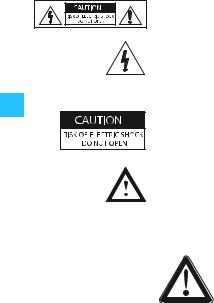
Symbols on adhesive labels attached to the device
The adjoining adhesive label is attached to the devices back. The symbols on this label have the following meaning:
This symbol is intended to alert the user to the presence of uninsulated dangerous voltage within the product's enclosure that may be of sufficient magnitude to constitute risk of fire or electric shock.
This symbol is intended to alert the user to the risk of electric shock if the unit cover or back is removed. There are no serviceable parts inside. Refer servicing to qualified personnel only.
This symbol is intended to alert the user to the presence of important operating and maintenance instructions in the literature accompanying this product.
Attention! High volume!
This is a professional transmission system. Commercial use is subject to the safety-at-work regulations. Sennheiser, as the manufacturer, is therefore obliged to expressly point out possible
health risks arising from use.
This system is capable of producing sound pressure exceeding 85 dB(A). 85 dB(A) is the sound pressure corresponding to the maximum permissible volume which is by law (in some countries) allowed to affect your hearing for the duration of a working day. It is used as a basis according to the specifications of industrial medicine. Higher volumes or longer durations can damage your hearing. At higher volumes, the duration must be shortened in order to prevent damage. The following are sure signs that you have been subjected to excessive noise for too long a time:
yYou can hear ringing or whistling sounds in your ears.
yYou have the impression (even for a short time only) that you can no longer hear high notes.
4

Intended use of the transmitter
Intended use includes
y having read these instructions especially the chapter “Safety instructions”.
yusing the transmitter within the operating conditions as described in these instructions.
Improper use
Improper use is when you use the transmitter other than described in these instructions or when you use the transmitter under operating conditions different from those described in these instructions.
5
SR 3254
SR 3256
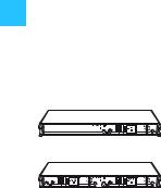
SR 3254/SR 3256 transmitters
With the wireless in-ear monitoring system, consisting of the SR 3254 or SR 3256 stereo transmitter and the EK 3253 bodypack receiver, musicians, video and sound amateurs, reporters/broadcasters, etc. can directly monitor the received sound signals without troublesome cables or monitor speakers being required. In addition, the system can also be used for any application where talkback signals are to be transmitted.
The system has superb audio quality with an increased signal- to-noise ratio and dynamic range due to the inclusion of Sennheiser’s HDX noise reduction system.
The SR 3254 is a single stereo transmitter in a 19" 1 U housing.
The SR 3256 consists of two complete stereo transmitters in a 19" 1 U housing.
The stereo transmitters have the following features:
yEasy to use
yStereo/mono selector switch
ySwitching bandwidth of 36 MHZ per transmitter
yTransmission frequencies tunable in steps of 5 kHz
yHDX noise reduction system with more than 90 dB signal-to- noise ratio
yLC display for frequency, RF output power and deviation
yRugged 19" housing with built-in mains unit; supplied with rack-mounting kit
ySuitable for multi-channel applications
yRF output power of up to 100 mW
6

The channel bank system
The SR 3254/SR 3256 transmitter is available in five UHF frequency ranges:
Range A: 518 to 554 MHz
Range B: 626 to 662 MHz
Range C: 740 to 776 MHz
Range D: 786 to 822 MHz
Range E: 830 to 866 MHz
The transmitter has two channel banks with up to 16 switchable channels each. The channels of the channel bank “F“ (fixed bank) have been factory-preset to customer-specific transmission frequencies. These frequencies cannot be changed.
The channel bank “U” (user bank) allows you to freely select and store frequencies.
Recommended receiver
y EK 3253
Delivery includes
y1 SR 3254 transmitter or
1 SR 3256 twin transmitter
y1 rack-mounting kit
y1 mains cable
y1 telescopic antenna (with the SR 3254) or
2 telescopic antennas (with the SR 3256)
yInstructions for use
7
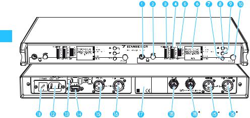
Overview of operating controls
Headphone output,
¼” (6.3 mm) jack socket
Headphone volume control
LCD bargraph for deviation of the left channel (DEV L), with overmodulation display (“PEAK”)
LCD bargraph for deviation of the
right channel and “MONO” (DEV R), with overmodulation display (“PEAK”)
LCD bargraph for RF output power (RF)
Alphanumeric LC display SET button
button (UP)
button (DOWN)
POWER button
Note:
Fuse holder and mains voltage selection (230 or 115 V)
2-pin IEC mains connector
Cable grip for mains cable
Programming interface, 15-pin sub-D socket
Audio input, left (AF IN (L))
Audio input, right (AF IN (R) + MONO)
Type plate
Antenna output
Connections and operating controls marked with a star ( ) in the above illustration are those for the second transmitter of the SR 3256 twin transmitter.
8
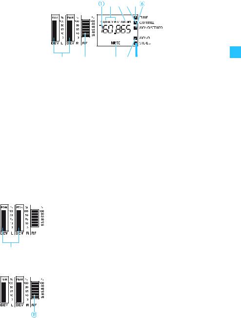
Indications and displays
|
Alphanumeric display
“FREQUENCY MHZ” display
“CHANNEL” display
LC dot CHANNEL
LC dot TUNE
LC dot MONO/STEREO
LC dot STEREO (transmitter is set to stereo operation)
LC dot MONO (transmitter is set to mono operation)
MUTE display (transmitter is muted)
6-step bargraph for RF output power
11-step deviation bargraph
(two separate bargraphs for the left and right channel)
Deviation display
The two bargraphs indicate the deviation of the audio signal of the left and right channel. When the transmitter’s audio input level is excessively high, “PEAK” lights up.
Display of the RF output power
The bargraph indicates the RF output power. During normal operation, an RF output power of 100 % is indicated.
9
Loading...