


233.52152
Sears 233.52152, 233.52059, 233.52153, 233.52057, 233.52157 User Manual
...
8! 8
OWNER'S
MAN UAL
Model Nos.
233.52052002
233.52053002
233.52057002
233.52059002
233.52152002
233.52153002
233.52157002
233.52159002
Caution:
Read and follow
all Safety Rules and
Operating Instructions
before first use of this
Product.
RANGE
HOOD
• Safety Instructions
. Installation Instructions
• Maintenance
• Replacement Parts List
• Warranty
Sears, Roebuck and Co., Hoffman Estates, IL 60179 U.S.A.
IMPORTANT SAFETY
INSTRUCTIONS
WARNING
WARNING -TO REDUCE THE RISK OF FIRE, ELECTRIC SHOCK, OR
II_LIRYTO PERSONS, OBSERVETHE FOLLOWING:
1. Use this unit only in the manner intended by the manufacturer. If
you have questions, contact the manufacturer at the address or
telephone number listed in the warranty.
2. Before servicing or cleaning unit, switch power off at service panel
and lock service panel to prevent power from being switched on
accidentally. When the service disconnecting means cannot be
locked,securely fasten a prominent warning device,such as a tag,
to the service panel. .
3. Installation work and electrical wiring must be done by a quali-
fied person(s) in accordance with all applicable codes and stan-
dards, including fire-rated construction codes and standards.
4. Sufficient air is needed for proper combustion and exhausting of
gases through the flue (chimney) of fuel burning equipment to
prevent backdrafting. Follow the heating equipment
manufacturer's guideline and safety standards such as those pub-
lished by the National Fire Protection Association (NFPA), and
the American Society for Heating, Refrigeration and Air Condi-
tioning Engineers (ASHRAE), and the local code authorities.
5. When cutting or drilling into wall or ceiling, do not damage elec-
trical wiring and other hidden utilities.
6. Ducted fans must always be vented to the outdoors.
7. To reduce the risk of fire, use only metal ductwork.
TO REDUCE THE RISK OF A RANGE TOP GREASE FIRE:
1. Never leave surface units unattended at high settings. J3oilovers
cause smoking and greasy spillovers that may ignite. Heat oils
slowly on low or medium settings.
2. Always turn hood ON when cooking at high heat .or when cook-
ing flaming foods.
3. Clean ventilating fans frequently. Grease should not be allowed
to accumulate on fan or filter.
4. Use proper pan size.Always uSe cookware appropriate for the
size of the surface element.
TO REDUCE THE RISK OF INJURY TO PERSONS IN THE EVENT
OFA RANGETOP GREASE FIRE, OBSERVETHE FOLLOWING*:
1. SMOTHER FLAMES with a close-fitting lid, cookie sheet, or metal
tray, then turn off the burner. BE CAREFULTO PREVENT BURNS.
If the flames do not go out immediately, EVACUATE AND CALL
THE FIRE DEPARTMENT.
2. NEVER PICK UP A FLAMING PAN -You may be burned.
3. DO NOT USE WATER, including wet dishcloths or towels - a vio-
lent steam explosion will result.
4. Use an extinguisher ONLY if:
A. You know you have a Class ARC extinguisher, and you al-
ready know how to operate it.
B. The fire is small and contained in the area where it started.
C. The fire department is being called.
D. You can fight the fire with your back to an exit.
• Based on _Kitchen Fir_safetyTips _ published by NFPA.
IMPORTANT SAFETY
INSTRUCTIONS
CAUTION
1. For general ventilating use only.Do not use to exhaust hazardous
or explosive materials and vapors.
2. To reduce the risk of Rre or electrical shock,this range hood should
not be used with an additional speed control device.
3. To reduce the risk of shock, disconnect power before servicing.
4. To reduce the risk of fire and to properly exhaust air, be sure to
duct air outside.
PLAN THE INSTALLATION
Recommended mounting height is 18 _to 24 _from the bottom of the
range hood to the top of the cooking surface.
The hood should be mounted to the bottom of a standard wall cabi-
net. If the hood must be mounted directly to a wall, secure the hood
to wall studs.
All wiring must comply with local codes and the unit must be prop-
erly grounded.The hood is connected to a 110-120vAC lighting cir-
cuit (15 amp) in the circuit breaker or fuse box.
This range hood is "Convertible'- it may be installed as a ducted or as
a non-ducted unit.
IFTHE RANGE HOOD ISTO BE NON-DUCTF, D:
• Purchase nonMucted (duct-free) charcoal filter Model BPQTE
IFTHE RANGE HOOD ISTO BE DUCTED:
• Ductwork can be installed vertically or horizontally.
• Duct runs should Be as short as possible.
• Avoid the use of elbows.
• Use duct tape at all joints.
• Do not use duct smaller than the discharge on the hood.
• For 7" round ductwork installation, use 7 _round damper, Model
BP87 (purchased separately).
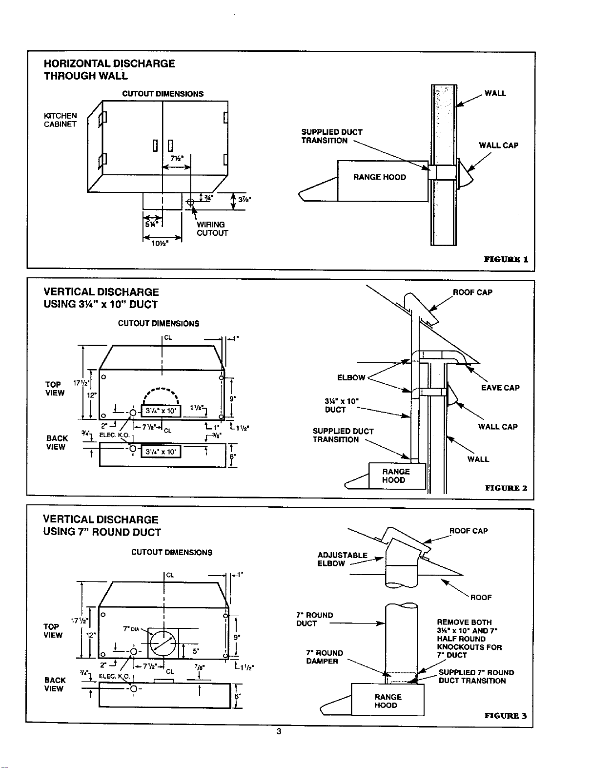
HORIZONTAL DISCHARGE
THROUGH WALL
CUTOUT DIMENSIONS
KITCHEN
CABINET
/
5¼"
DD
7½"
__ w_&
SUPPUED DUCT
TRANSmON
RANGEHOOD
/ WALL
WALL CAP
In[G_ I
VERTICAL DISCHARGE
USING 3V4" x 10" DUCT
TOP
VIEW
BACK
VIEW
CUTOUT DIMENSIONS
_'J/I--_"="I_L L,.
a!'{] ELEC.K.O._ r--3/_"
-- ",.I _ T
T
9"
1
t-11/2"
3Y4"X 10"
DUCT
SUPPLIED DUCT
TRANSITION
RANGE
HOOD
ROOF CAP
WALL
EAVE CAP
WALL CAP
VERTICAL DISCHARGE
USING 7" ROUND DUCT
TOP
VIEW
BACK
VIEW
CUTOUT DIMENSIONS
CL
17 = TDL_
_.J/'l-_,,,:: ,,..
X_- ,o- I
J
9"
Lll/2 .
IF_
ROOFCAP
ADJUSTABLE
ELBOW
_""ROOF
7"ROUND
DUCT
RANGE
HOOD
7"ROUND
DAMPER
REMOVE BOTH
3½" x 10" AND7"
HALF ROUND
KNOCKOUTS FOR
7" DUCT
_UPPLIED 7" ROUND
DUCT TRANSITION
_GtrBLE 3
PREPARATION
1. Use the dimensional drawings (Refer to FIGURES 1 - 3) to lay
out the range hood's mounting holes, vin'ing access and ductwork
by marking the cabinet bottom and drywall where applicable.
2. Make cutouts for wiring and ductwork.
3. If the hood is to be ducted,install the ductwork so that is flush to
the range hood's mounting surface.
Refer to FIGURE 1 if the range hood is to be installed with a
horizontal discharge.
Refer to FIGURE 2 and FIGURE 3 if the range hood is to be
installed with a vertical discharge.
4. Run two-conductor wire (with ground) from a power source to
the hood location.B(mg approximately 12"of wiring through wir-
ing hole in cabinet.
5. DriU four 3/32" diameter pilot holes at points where mounting
holes are marked in cabinet bottom.
6. Insert four (4) mounting screws, leaving approximately ¼" of
thread exposed.
7. Remove and retain the mounting screws securing the 3¼"x 10"
and 7 _ duct transitions to the hood. Install the appropriate duct
transition as described in the installation section.
IN STALLATIO N
1. Remove the necessary duct opening and wiring knockout from
the range hood.
If the range hood is to be installed as a non-ducted unit, re-
move the wiring knockout only.
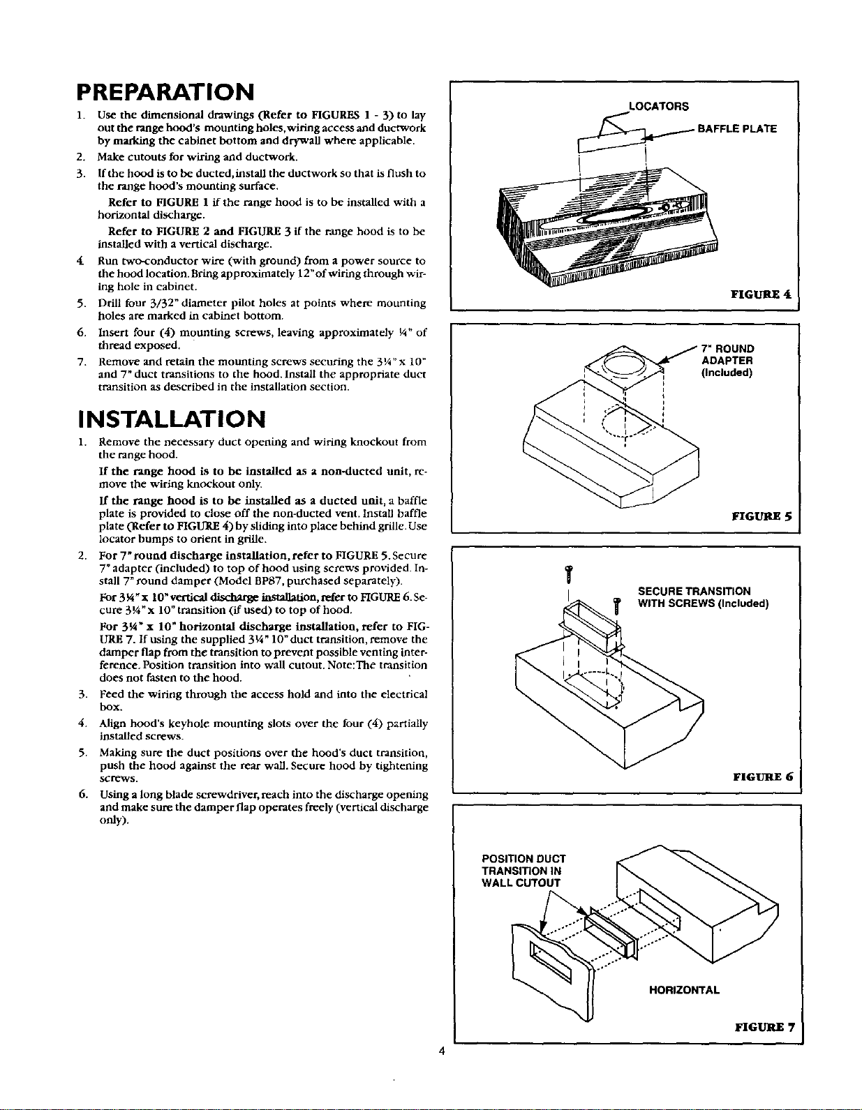
If the range hood is to be installed as a dueted unit, a baffle
plate is provided to close off the nonMucted vent. InstaB baffle
plate (Refer to FIGURE 4) by sliding into place behind grille. Use
locator bumps to orient in grille.
2. For 7" round discharge installation, refer to FIGURE 5. Secure
7" adapter (included) to top of hood using screws provided, in-
stall 7" round damper (Model BPg7, purchased separately).
For 3V_x 10" vertical _ installation, refer to FIGURE 6. Se-
cure 3¼" x 10" transition (if used) to top of hood.
For 3_i" x 10" horizontal discharge installation, refer to FIG-
URE 7. If using the supplied 3¼ _ 10" duct transition, remove the
damper flap from the transition to prevent possible venting inter-
ference. Position transition into wall cutout. Note:The transition
does not fasten to the hood.
3. Feed the wiring through the access hold and into the electrical
box.
4. Align hood's keyhole mounting slots over the four (4) partially
installed screws.
5. Making sure the duct positions over the hood's duct transition,
push the hood against the rear wail. Secure hood by tightening
SCreWS.
6. Using a long blade screwdriver, reach into the discharge opening
and make sure the damper flap operates freely (vertical discharge
only).
LOCATORS
_ BAFFLE PLATE
FIGURE 4
ADAPTER
(Included)
FIGURE 5
SECURE TRANSITION
T WITH SCREWS (Included)
FIGURE 6
POSITION DUCT
TRANSITION iN
WALL CUTOUT
÷,°
HORIZONTAL
FIGUILE7
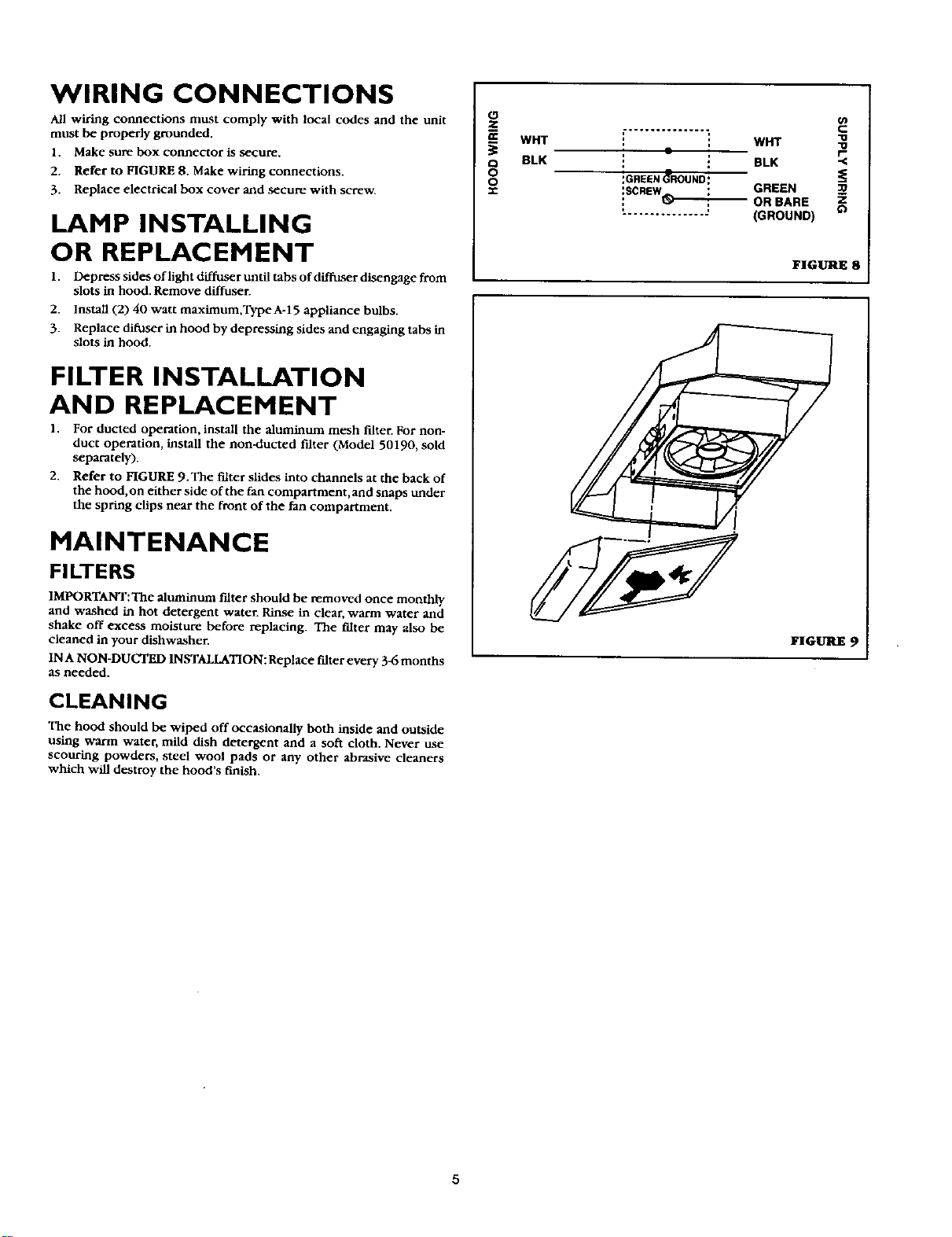
WIRING CONNECTIONS
All wiring connections must comply with local codes and the unit
must be properly grounded.
1. Make sure box connector is secure.
2. Refer to FIGURE 8. Make wiring connections.
3. Replace electrical box cover and secure with screw.
LAMP INSTALLING
OR REPLACEMENT
1. Depress sides of light diffuser until tabs of diShlser disengage from
slots in hood. Remove diffuser.
2. Install (2) 40 watt maximum,Type A-15 appliance bulbs.
3. Replace difuser in hood by depressing sides and engaging tabs in
slots in hood.
FILTER INSTALLATION
AND REPLACEMENT
1. For ducted operation, install the aluminum mesh filter. For non-
duct operation, install the non-ducted filter (Model 50190, sold
separately).
2. Refer to FIGURE 9. The filter slides into channels at the back of
the hood,on either side of the fan compartment,and snaps under
the spring clips near the front of the fan compartment.
MAINTENANCE
FILTERS
IMPORTANT:The aluminum filter should be removed once monthly
and washed in hot detergent water. Rinse in clear, warm water and
shake off excess moisture before replacing. The fdter may also be
cleaned in your dishwasher.
INA NON-DUCTED INSTALLATION:Replace filter every 3_ months
as needed.
CLEANING
The hood should be wiped off occasionally both inside and outside
using warm water, mild dish detergent and a soft cloth. Never use
scouring powders, steel wool pads or any other abrasive cleaners
which will destroy the hood's finish.
O
WHT
BLK
O
O
0'J
' i WHT
• . BLK
:GREEN_ROUND:
:SCREW : GREEN
: _-"_OR BARE
.............. : (GROUND) O
FIGURE8
FIGURE 9
5
 Loading...