


Owner’s Manual
THE ECONOMIZER™ 6 GAS WATER HEATER
POWER VENTED GAS MODELS WITH HOT SURFACE IGNITION
FOR POTABLE WATER HEATING ONLY.
NOT SUITABLE FOR SPACE HEATING.
NOT FOR USE IN MOBILE HOMES.
MODEL NO.
153.332040 |
40 Gallon Nat |
153.332050 |
50 Gallon Nat |
153.332060 |
40 Gallon LP |
153.332070 |
50 Gallon LP |
•Safety Instructions
•Installation
•Operation
•Care and Maintenance
•Troubleshooting
•Parts List
For Your Safety
AN ODORANTISADDEDTOTHE GAS USED BYTHIS WATER HEATER.
C3 Technology® Gas Water Heaters meet the new ANSI Z21.10.1 standard that deals with the accidental or unintended ignition of flammable vapors, such as those emitted by gasoline.
ADVERTENCIA
Si no puede leer o entender el inglés y necesita el manual instructivo y/o etiquetas en español puede obtenerlos llamando al 1-800-821-2017. NO TRATE DE INSTALAR O OPERAR ESTE CALENTADOR DEAGUAsi no entiende la información en las etiquetas o en el manual instructivo. No hacer caso de esta advertencia podría resultar en la MUERTE O GRAVESLESIONESCORPORALES.
Sears, Roebuck and Co., Hoffman Estates, IL 60179 U.S.A
PRINTED IN THE U.S.A. 0905 |
www.sears1 .com |
PART NO. 185249-000 |
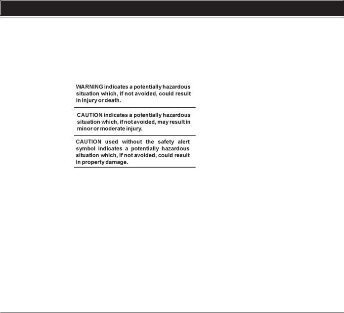
SAFE INSTALLATION, USE AND SERVICE
Your safety and the safety of others is extremely important in the installation, use and servicing of this water heater.
Many safety-related messages and instructions have been provided in this manual and on your own water heater to warn you and others of a potential injury hazard. Read and obey all safety messages and instructions throughout this manual. It is very important that the meaning of each safety message is understood by you and others who install, use or service this water heater.
All safety messages will generally tell you about the type of hazard, what can happen if you do not follow the safety message and how to avoid the risk of injury.
IMPORTANT DEFINITIONS
•Gas Supplier: The Natural Gas or Propane Utility or service who supplies gas for utilization by the gas burning appliances within this application. The gas supplier typically has responsibility for the inspection and code approval of gas piping up to and including the Natural Gas meter or Propane storage tank of a building. Many gas suppliers also offer service and inspection of appliances within the building.
© Sears, Roebuck and Co.
2
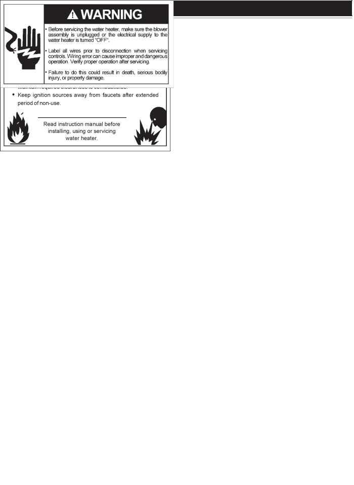
SAFETY PRECAUTIONS
3

TABLE OF CONTENTS |
|
SAFE INSTALLATION, USE AND SERVICE .................................................................................................................................... |
2 |
SAFETY PRECAUTIONS ................................................................................................................................................................. |
3 |
TABLE OF CONTENTS .................................................................................................................................................................... |
4 |
CUSTOMER RESPONSIBILITIES ................................................................................................................................................... |
5 |
PRODUCT SPECIFICATIONS ......................................................................................................................................................... |
5 |
MATERIALS AND BASIC TOOLS NEEDED .................................................................................................................................... |
6 |
TYPICAL INSTALLATION .................................................................................................................................................................. |
7 |
INSTALLATION INSTRUCTIONS .............................................................................................................................................. |
8-21 |
Removing the Old Water Heater ............................................................................................................................................. |
8 |
Facts to Consider About the Location .............................................................................................................................. |
9-10 |
Insulation Blankets ................................................................................................................................................................. |
10 |
Combustion Air and Ventilation for Appliances Located in Unconfined Spaces ............................................................. |
10 |
Combustion Air and Ventilation for Appliances Located in Confined Spaces ............................................................ |
10-11 |
Water Piping ...................................................................................................................................................................... |
12-13 |
Temperature-Pressure Relief Valve ............................................................................................................................... |
13-14 |
Gas Piping ......................................................................................................................................................................... |
14-15 |
Sediment Traps ...................................................................................................................................................................... |
15 |
Filling the Water Heater ......................................................................................................................................................... |
15 |
Blower Assembly Installation .......................................................................................................................................... |
15-16 |
Vent Connections to Blower Assembly ................................................................................................................................. |
17 |
Venting and Installation ......................................................................................................................................................... |
17 |
Condensation ......................................................................................................................................................................... |
17 |
Maximum Vent Lengths .......................................................................................................................................................... |
17 |
Venting ..................................................................................................................................................................................... |
18 |
Vent Terminal Installation ................................................................................................................................................ |
18-19 |
Vertical Vent Through Roof ..................................................................................................................................................... |
19 |
Vertical Vent Termination Restrictions .................................................................................................................................. |
19 |
Vent Pipe Preparation ...................................................................................................................................................... |
20-21 |
OPERATING INSTRUCTIONS ................................................................................................................................................. |
22-23 |
Lighting and Operating Label ............................................................................................................................................... |
22 |
Temperature Regulation ........................................................................................................................................................ |
23 |
FOR YOUR INFORMATION ...................................................................................................................................................... |
24-25 |
Start Up Conditions .......................................................................................................................................................... |
24-25 |
Operational Conditions .......................................................................................................................................................... |
25 |
SERVICE AND ADJUSTMENT ................................................................................................................................................. |
25-27 |
Venting System Inspection .................................................................................................................................................... |
25 |
Burner Operation and Inspection ................................................................................................................................... |
25-26 |
Burner Cleaning ..................................................................................................................................................................... |
26 |
Housekeeping ........................................................................................................................................................................ |
26 |
Anode Rod Inspection ............................................................................................................................................................ |
26 |
Temperature-Pressure Relief Valve Operation ............................................................................................................. |
26-27 |
Draining ................................................................................................................................................................................... |
27 |
Drain Valve Washer Replacement ........................................................................................................................................ |
27 |
Service ..................................................................................................................................................................................... |
27 |
LEAKAGE CHECKPOINTS ............................................................................................................................................................ |
28 |
TROUBLESHOOTING GUIDELINES ...................................................................................................................................... |
29-30 |
REPAIR PARTS LIST ...................................................................................................................................................................... |
31 |
WARRANTY ..................................................................................................................................................................................... |
32 |
4

CUSTOMER RESPONSIBILITIES
Thank You for purchasing a Kenmore water heater. Properly installed and maintained, it should give you years of trouble free service. If you should decide that you want the new water heater professionally installed by Sears call 1-800-4-MY-HOME®. They will arrange for prompt, quality installation by Sears authorized contractors.
Abbreviations Found In This Instruction Manual:
•CSACanadian Standards Association
•ANSI -American National Standards Institute
•NFPANational Fire ProtectionAssociation
•ASME - American Society of Mechanical Engineers
•GAMA - GasAppliance Manufacturer’s Association
•UL - Underwriters Laboratories Inc.
This gas-fired water heater is listed by Underwriters Laboratories Inc. underAmerican National Standard/CSAStandard for Gas Water Heaters ANSI Z21.10.1 • CSA 4.1 (current edition).
2.The installation must conform with these instructions and the local code authority having jurisdiction. In the absence of local codes, installations shall comply with the National Fuel Gas CodeANSI Z223.1/ NFPA54 and the National Electrical Code, NFPA70.These publications are available from The National Fire Protection Association, 1 Batterymarch Park, Quincy, MA 02269.
3.The water heater when installed must be grounded in accordance with the local codes, or in the absence of local codes, the National Electrical Code NFPA70.
4.If after reading this manual you have any questions or do not understand any portion of the instructions, call the local gas utility or the Sears Service Center.
5.Carefully plan the place where you are going to put the water heater. Correct combustion, vent action, and vent pipe installation are very important in preventing death from possible carbon monoxide poisoning and fires.
PREPARING FOR THE INSTALLATION
1.Read the “Safety Precautions” section, page 3 of this manual first and then the entire manual carefully. If you don’t follow the safety rules, the water heater will not operate properly. It could cause DEATH,SERIOUSBODILYINJURYAND/ORPROPERTYDAMAGE.
This manual contains instructions for the installation, operation, and maintenance of the gas-fired water heater. It also contains warnings throughout the manual that you must read and be aware of. All warnings and all instructions are essential to the proper operation of the water heater and your safety. Since we cannot put everything on the first few pages, READ THE ENTIRE MANUAL BEFORE
ATTEMPTING TO INSTALLOROPERATETHEWATERHEATER.
Examine the location to ensure the water heater complies with the “Facts to ConsiderAbout the Location” section in this manual.
6.For California installation this water heater must be braced, anchored, or strapped to avoid falling or moving during an earthquake. See instructions for correct installation procedures. Instructions may be obtained from California Office of the State Architect, 400 P Street, Sacramento, CA 95814.
7.Massachusetts Code requires this water heater to be installed in accordance with Massachusetts 248-CMR 2.00: State Plumbing Code and 248-CMR 5.00.
8.Complies with SCAQMD rule #1121 and districts having equivalent NOx requirements.
PRODUCT SPECIFICATIONS
|
TANK |
|
|
RECOVERY |
MINIMUM |
|
|
||
|
CAPACITY |
|
INPUT |
RATE GALS. |
VENT PIPE |
DIAMETER |
DIMENSIONS IN |
||
MODEL |
IN GALS. |
TYPE OF |
RATE |
PERHOUR |
INCHES |
INCHES |
INCHES (mm) HEIGHT |
||
NUMBER |
(LTRS) |
GAS |
(Btu/hr) |
@ 90°F RISE |
(mm) |
(mm) |
TO JACKET TOP |
||
|
|
|
|
|
|
|
|
|
|
153.332040 |
40 |
(151) |
NATURAL |
40,000 |
44 |
2 |
(51) |
18 1/2 (470) |
55 (1,397) |
|
|
|
|
|
|
|
|
|
|
153.332050 |
50 |
(189) |
NATURAL |
40,000 |
44 |
2 |
(51) |
20 (508) |
56 3/4 (1,441) |
|
|
|
|
|
|
|
|
|
|
153.332060 |
40 |
(151) |
PROPANE |
40,000 |
44 |
2 |
(51) |
18 1/2 (470) |
55 (1,397) |
|
|
|
|
|
|
|
|
|
|
153.332070 |
50 |
(189) |
PROPANE |
40,000 |
44 |
2 |
(51) |
20 (508) |
56 3/4 (1,441) |
|
|
|
|
|
|
|
|
|
|
5
MATERIALS AND BASIC TOOLS NEEDED
Materials Needed
To simplify the installation Sears has available the installation parts shown below. You may or may not need all of these materials, depending on your type of installation.
EXPANSION TANKS FOR THERMAL EXPANSION CONDITIONS AVAILABLE IN 2 GALLONS
(7.6 LITERS) AND
5 GALLONS (18.9 LITERS) CAPACITY THROUGH LOCAL SEARS STORE OR SERVICE CENTER.
WATER HEATER INSTALLATION KIT WITH FLEXIBLE CONNECTORS FOR 3/4”
(19.05 mm) OR 1/2” (12.7 mm) THREADED OR COPPER PLUMBING AND FLEXIBLE GAS CONNECTOR WITH FITTINGS.
DRAIN PANS AVAILABLE IN 20” (508 mm) DIAMETER FOR WATER HEATERS HAVING A DIAMETER 18” (457 mm) OR LESS, 24” (610mm) DIAMETER FOR WATER HEATERS HAVING A DIAMETER 22” (559 mm) OR LESS AND AVAILABLE IN 28” (711 mm) DIAMETER FOR WATER HEATERS HAVING A DIAMETER 26” (660 mm) OR LESS.
Basic Tools
You may or may not need all these tools, depending on your type of installation. These tools can be purchased at your local Sears Store.
•Pipe Wrenches (2) 14” (356 mm)
•Screwdriver
•Tin Snips
•6’ (1.82 m) Tape or Folding Ruler
•Garden Hose
•Drill
• Pipe Dope or Teflon Tape |
DRILL |
SLOT-HEAD SCREWDRIVER
TIN SNIPS
PHILLIPS SCREWDRIVER
|
PIPE DOPE |
ROLL OF TEFLON |
(SQUEEZE TUBE) |
TAPE (USE ONLY ON |
USE FOR WATER AND GAS |
WATER CONNECTIONS) |
CONNECTIONS |
GARDEN HOSE |
6 FOOT TAPE |
PIPE WRENCH |
Additional Tools Needed
When Sweat Soldering
•Tubing Cutters or Hacksaw
•Propane Tank
•Soft Solder
•Solder Flux
•Emery Cloth
•Wire Brushes
|
PROPANE |
TUBING CUTTER |
TORCH |
|
ROLL OF |
HACKSAW |
EMERY CLOTH |
3/4” (19 mm) WIRE BRUSH |
|
|
|
ROLL OF LEAD-FREE |
SOLDER |
1/2” (13 mm) WIRE BRUSH |
SOFT SOLDER |
FLUX |
6

TYPICAL INSTALLATION
GET TO KNOW YOUR WATER HEATER - GAS MODELS
A |
Vent Pipe–Exhaust |
K |
Hot Water Outlet |
V |
Drip Leg (Sediment Trap) |
B |
Vent Terminal |
L |
Outlet Receptacle (115 VAC) |
W |
Drain Valve |
C |
Vent Adapter-Rubber Boot |
M |
Temperature-Pressure Relief Valve |
X |
Gas Valve-Thermostat |
D |
Blower Assembly |
N |
Flue |
Y |
Drain Pan |
E |
Cold Water Inlet |
O |
Flue Baffle Assembly** |
Z |
Air Intake Screen - Base Pan |
F |
Inlet Water Shut-off Valve |
P |
Insulation |
AA |
Inner Door |
G |
Union |
Q |
Control Harness |
BB |
Outer Door |
H |
Inlet Dip Tube |
R |
Rating Plate |
CC |
HSI Burner Assembly |
J |
Anode** |
S |
Gas Supply |
DD |
Air Intake Screen - |
|
|
T |
Manual Gas Shut-off Valve |
|
Blower Assembly |
|
|
U |
Ground Joint Union |
EE |
FV Sensor Assembly |
*ALL PIPING MATERIALS TO BE SUPPLIED BY CUSTOMERS.
**LOCATED UNDER THE BLOWER ASSEMBLY.
NATURAL HOT SURFACE IGNITER & MAIN BURNER
HOT
SURFACE
IGNITOR
SENSOR
PROPANE HOT SURFACE IGNITER & MAIN BURNER
HOT
SURFACE
IGNITOR
SENSOR
TEMPERATURE INDICATORS
*CAUTION: 115 VAC IN CONTROL HARNESS AND INSIDE OUTER DOOR
GAS MODELS
WITH HOT SURFACE IGNITION
& 2", 3" OR 4" PVC VENT CAPABILITY
FIGURE1.
7
INSTALLATION INSTRUCTIONS
Removing the Old Water Heater
FIGURE2. |
|
|
1. Turn “OFF” the gas supply to the water |
|
|
|
||
heater. |
|
|
If the main gas line Shut-off valve |
|
|
serving all gas appliances is used, also |
|
|
shut “OFF” the gas at each appliance. |
|
|
Leave all gas appliances shut “OFF” |
|
|
until the water heater installation is |
|
|
|
||
completed, see Figures 2 and 3. |
FIGURE3. |
|
2. Turn “OFF” the water supply to the |
|
|
|
||
water heater at the water shut off |
|
|
valve or water meter. Some |
|
|
installations require that the water be |
|
|
turned off to the entire house, see |
|
|
Figures 2 and 4. |
|
|
FIGURE4. |
||
|
3.Check again to make sure the gas supply is “OFF” to the water heater. Then disconnect the gas supply connection from the gas control valve.
4.Attach a hose to the water heater drain valve and put the other end in a floor drain or outdoors. Open the water heater drain valve. Open a nearby hot water faucet which will relieve pressure in the water heater and speed draining. The water passing out of the drain valve may be extremely hot. To avoid being scalded, make sure all connections are tight and that the water flow is directed away from any person, see Figures 2 and 5.
FIGURE5.
5.Disconnect the vent pipe from the blower assembly where it connects to the water heater. In most installations the vent pipe can be lifted off
after any screw or other attached devices are removed. Make sure existing vent complies with maximum and minimum vent lengths on page 17.
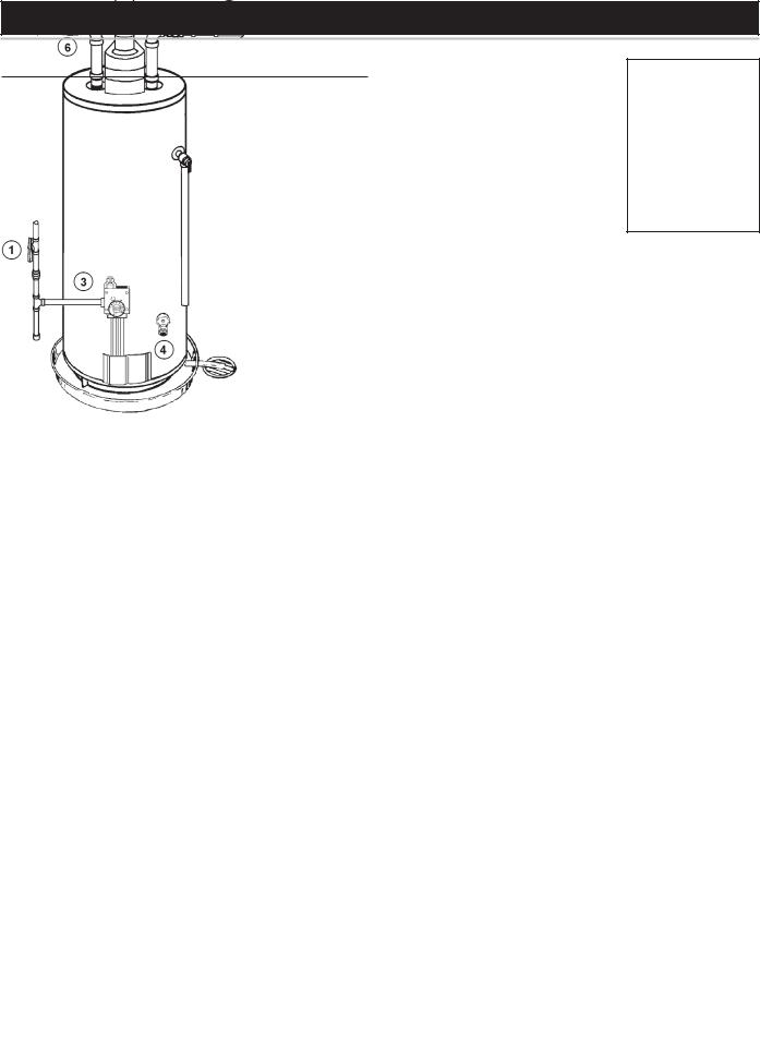
6.If you have copper piping to the water heater, the two copper water pipes can be cut with a hacksaw approximately four inches away from where they connect to the water heater, see Figure 6. This will avoid cutting off pipes too short. Additional cuts can be made later if necessary. Disconnect the temperature-pressure relief valve drain line. When the water heater is drained, disconnect the hose from the drain valve. Close the drain valve. The water heater is now completely disconnected and ready to be removed.
FIGURE6.
If you have galvanized pipes to the water heater, loosen the two galvanized pipes with a pipe wrench at the union in each line. Also disconnect the piping remaining to the water heater, see Figure 7. These pieces should be saved since they may be needed when reconnecting the new water heater. Disconnect the temperaturepressure relief valve drain line. When the water heater is drained, disconnect the hose from the drain valve. Close the drain valve. The water heater is now completely disconnected and ready to be removed. Mineral buildup or sediment may have accumulated in the old water heater. This causes the water heater to be much heavier than normal and this residue, if spilled out, could cause staining.
FIGURE7.
8

FACTS TO CONSIDER ABOUT THE LOCATION
Carefully choose an indoor location for the new water heater, because the placement is a very important consideration for the safety of the occupants in the building and for the most economical use of the appliance.
This water heater is not for use in manufactured (mobile) homes or outdoor installation.
Whether replacing an old water heater or putting the water heater in a new location, the following critical points must be observed:
1.Select a location indoors as close as practical to the vent terminal or location to which the water heater vent piping is going to be connected, and as centralized with the water piping system as possible.
2.Selected location must provide adequate clearances for servicing and proper operation of the water heater.
Installation of the water heater must be accomplished in such a manner that if the tank or any connections should leak, the flow will not cause damage to the structure. For this reason, it is not advisable to install the water heater in an attic or upper floor. When such locations cannot be avoided, a suitable drain pan should be installed under the water heater. Drain pans are available at your local hardware store. Such a drain pan must have a minimum length and width of at least 2" (5.1 cm) greater than the water heater dimensions and must be piped to an adequate drain. The pan must not restrict combustion air flow.
Water heater life depends upon water quality, water pressure and the environment in which the water heater is installed. Water heaters are sometimes installed in locations where leakage may result in property damage, even with the use of a drain pan piped to a drain. However, unanticipated damage can be reduced or prevented by a leak detector or water shut-off device used in conjunction with a piped drain pan. These devices are available from some plumbing supply wholesalers and retailers, and detect and react to leakage in various ways:
•Sensors mounted in the drain pan that trigger an alarm or turn off the incoming water to the water heater when leakage is detected.
•Sensors mounted in the drain pan that turn off the water supply to the entire home when water is detected in the drain pan.
•Water supply shut-off devices that activate based on the water pressure differential between the cold water and hot water pipes connected to the water heater.
•Devices that will turn off the gas supply to a gas water heater while at the same time shutting off its water supply.
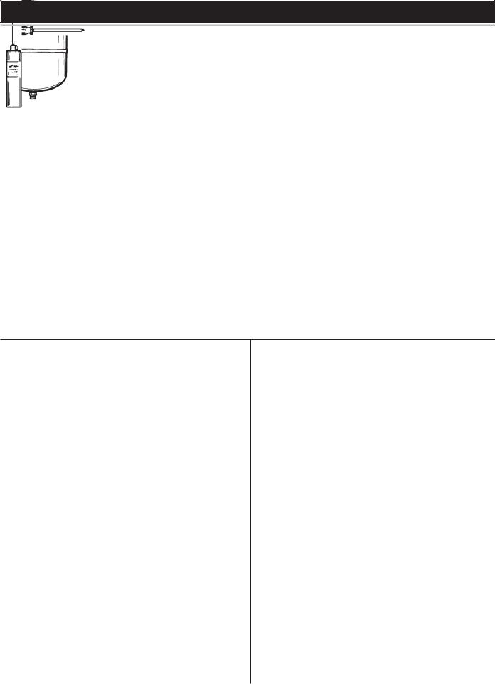
INSTALLATIONS INAREAS WHERE FLAMMABLE LIQUIDS (VAPORS) ARELIKELYTOBEPRESENTORSTORED(GARAGES,STORAGEAND UTILITYAREAS, ETC.): Flammable liquids (such as gasoline, solvents, propane (LP or butane, etc.) and other substances (such as adhesives, etc.) emit flammable vapors which can be ignited by a gas water heater’s hot surface igniter or main burner. The resulting flashback and fire can cause death or serious burns to anyone in the area. This water heater is equipped with a FV sensor for detecting the presence of flammable vapors, see Figure 8. When the sensor detects those vapors, the unit will shut down and not operate. Should this happen, please refer to the troubleshooting guide on pages 29-30. Even though this water heater is a flammable vapors ignition resistant water heater and is designed to reduce the chances of flammable vapors being ignited, gasoline and other flammable substances should never be stored or used in the same vicinity or area containing a gas water heater or other open flame or spark producing appliance.
FIGURE8.
Also, the water heater must be located and/or protected so it is not subject to physical damage by a moving vehicle.
This water heater must not be installed directly on carpeting. Carpeting mustbeprotectedbymetalorwoodpanelbeneaththeapplianceextending beyond the full width and depth of the appliance by at least 3" (7.6 cm) in any direction, or if the appliance is installed in an alcove or closet, the entire floor must be covered by the panel. Failure to heed this warning may result in a fire hazard.
Minimum clearances between the water heater and combustible construction are 0 inch at the sides and rear, 5" (12.7 cm) from the front
9

and 12" (30.5 cm) from the top. (Standard clearance.) If clearances stated on the heater differ from standard clearances, install water heater according to clearances stated on the heater.
Adequate clearance for servicing this appliance should be considered before installation, such as changing the anodes, etc.
A minimum clearance of 5" (12.7 cm) must be allowed for access to replaceable parts such as the thermostats, drain valve and relief valve.
When installing the heater, consideration must be given to proper location. Location selected should be as close to the wall as practicable and as centralized with the water piping system as possible.
FIGURE9.
flammable in many cases, will also react to form corrosive hydrochloric acid when exposed to the combustion products of the water heater. The results can be hazardous, and also cause product failure.
INSULATION BLANKETS
Insulation blankets are available to the general public for external use on gas water heaters but are not necessary with Kenmore products. The purpose of an insulation blanket is to reduce the standby heat loss encountered with storage tank heaters. Your Kenmore water heater meets or exceeds the National Appliance Energy Conservation Act standards with respect to insulation and standby loss requirements, making an insulation blanket unnecessary.
A gas water heater cannot operate properly without the correct amount of air for combustion. Do not install in a confined area such as a closet, unless you provide air as shown in the “Facts to Consider About the Location” section. Never obstruct the flow of ventilation air. If you have any doubts or questions at all, call your gas supplier. Failure to provide the proper amount of combustion air can result in a fire or explosion and cause death, serious bodily injury, or property damage.
FIGURE10.
If this water heater will be used in beauty shops, barber shops, cleaning establishments, or self-service laundries with dry cleaning equipment, it is imperative that the water heater or water heaters be installed so that combustion and ventilation air be taken from outside these areas.
Propellants of aerosol sprays and volatile compounds, (cleaners, chlorine based chemicals, refrigerants, etc.) in addition to being highly
Should you choose to apply an insulation blanket to this heater, you should follow these instructions (For identification of components mentioned below, see Figure 1). Failure to follow these instructions can restrict the air flow required for proper combustion, potentially resulting in fire, asphyxiation, serious personal injury or death.
•Do not apply insulation to the top of the water heater, as this will interfere with safe operation of the blower assembly.
•Do not cover the outer door, thermostat or temperature & pressure relief valve.
•Do not allow insulation to come within 2" (5.1 cm) of the floor to prevent blockage of combustion air flow to the burner.
•Do not cover the instruction manual. Keep it on the side of the water heater or nearby for future reference.
•Do obtain new warning and instruction labels from Sears for placement on the blanket directly over the existing labels.
•Do inspect the insulation blanket frequently to make certain it does not sag, thereby obstructing combustion air flow.
COMBUSTION AIR AND VENTILATION FOR APPLIANCES LOCATED IN UNCONFINED SPACES
UNCONFINED SPACE is space whose volume is not less than 50 cubic feet per 1,000 Btu per hour (4.8 cubic meters per kW) of the aggregate input rating of all appliances installed in that space. Rooms communicating directly with the space in which the appliances are installed, through openings not furnished with doors, are considered a part of the unconfined space.
In unconfined spaces in buildings, infiltration may be adequate to provide air for combustion, ventilation and dilution of flue gases. However, in buildings of tight construction (for example, weather stripping, heavily insulated, caulked, vapor barrier, etc.), additional air may need to be provided using the methods described in “CombustionAir and Ventilation for Appliances Located in Confined Spaces.”
COMBUSTION AIR AND VENTILATION FOR APPLIANCES LOCATED IN CONFINED SPACES
CONFINED SPACE is a space whose volume is less than 50 cubic feet per 1,000 Btu per hour (4.8 cubic meters per kW) of the aggregate input rating of all appliances installed in that space.
10
 Loading...