


 ®
®
Models SC-600A, SC-1000A, SC-1200A, SSC-1000A, SSC-1500A
SC-600A |
SC-1000A |
SC-1200A
SSC-1000A |
SSC-1500A |
Owner’s Manual
READ ENTIRE MANUAL BEFORE
USING THIS PRODUCT
00-99-000909/0109

Table of Contents
SECTION |
PAGE |
IMPORTANT SAFETY INSTRUCTIONS |
1 |
PERSONAL PRECAUTIONS |
2 |
PREPARING TO CHARGE |
3 |
CHARGER LOCATION |
3 |
DC CONNECTION PRECAUTIONS |
3 |
FOLLOW THESE STEPS WHEN BATTERY IS |
|
INSTALLED IN VEHICLE. |
4 |
FOLLOW THESE STEPS WHEN BATTERY IS |
|
OUTSIDE VEHICLE. |
4 |
battery charging - ac connections |
5 |
control panel |
6 |
Assembly Instructions |
9 |
operating instructions |
9 |
CALCULATING charge time |
13 |
maintenance instructions |
15 |
storage instructions |
15 |
troubleshooting |
15 |
Limited warranty |
18 |

IMPORTANT: read and save this safety and instruction manual.
1.IMPORTANT SAFETY INSTRUCTIONS
1.1SAVE THESE INSTRUCTIONS – The SpeedCharge Series battery chargers offer a wide range of features to accommodate the needs for home or light commercial use. This manual will show you how to use your charger safely and effectively. Please read, understand and follow these instructions and precautions carefully, as this manual contains important safety and operating instructions.
1.2WARNING: Pursuant to California Proposition 65, this product contains chemicals known to the State of California to cause cancer and birth defects or other reproductive harm.
1.3Do not expose charger to rain or snow.
1.4Use only recommended attachments. Use of an attachment not recommended or sold by Schumacher® Electric Corporation may result in a risk of fire, electric shock or injury to persons.
1.5To reduce the risk of damage to electric plug or cord, pull by the plug rather than the cord when disconnecting the charger.
1.6An extension cord should not be used unless absolutely necessary. Use of an improper extension cord could result in a risk of fire and electric shock. If an extension cord must be used, make sure:
•That the pins on the plug of the extension cord are the same number, size and shape as those of the plug on the charger.
•That the extension cord is properly wired and in good electrical condition.
•That the wire size is large enough for the AC ampere rating of the charger as specified in the table in section 8.
1.7Do not operate the charger with a damaged cord or plug; take it to a qualified service person. (Call customer service at: 1-800-621-5485.)
1.8Do not operate the charger if it has received a sharp blow, been dropped or otherwise damaged in any way; take it to a qualified service person. (Call customer service at: 1-800-621-5485.)
1.9Do not disassemble the charger; take it to a qualified service person when service or repair is required. Incorrect reassembly may result in a risk of fire or electric shock. (Call customer service at: 1-800-621-5485.)
1.10To reduce the risk of electric shock, unplug the charger from the outlet before attempting any maintenance or cleaning. Simply turning off the controls will not reduce this risk.
WARNING – RISK OF EXPLOSIVE GASES.
•1 •

WORKING IN THE VICINITY OF A LEAD-ACID BATTERY IS DANGEROUS. BATTERIES GENERATE EXPLOSIVE GASES DURING NORMAL BATTERY OPERATION. FOR THIS REASON, IT IS OF UTMOST IMPORTANCE THAT YOU FOLLOW THE INSTRUCTIONS EACH TIME YOU USE THE CHARGER.
TO REDUCE THE RISK OF BATTERY EXPLOSION, FOLLOW THESE INSTRUCTIONS AND THOSE PUBLISHED BY THE BATTERY MANUFACTURER AND THE MANUFACTURER OF ANY EQUIPMENT YOU INTEND TO USE IN THE VICINITY OF THE BATTERY. REVIEW THE CAUTIONARY MARKINGS ON THESE PRODUCTS AND ON THE ENGINE.
2.PERSONAL PRECAUTIONS
2.1Consider having someone close enough by to come to your aid when you work near a lead-acid battery.
2.2Have plenty of fresh water and soap nearby in case battery acid contacts your skin, clothing or eyes.
2.3Wear complete eye and body protection, including safety goggles and protective clothing. Avoid touching your eyes while working near the battery.
2.4If battery acid contacts your skin or clothing, wash immediately with soap and water. If acid enters your eye, immediately flood the eye with cold running water for at least 10 minutes and get medical attention right away.
2.5NEVER smoke or allow a spark or flame in the vicinity of a battery or engine.
2.6Be extra cautious to reduce the risk of dropping a metal tool onto the battery. It might spark or short-circuit the battery or other electrical part that may cause an explosion.
2.7Remove personal metal items such as rings, bracelets, necklaces and watches when working with a lead-acid battery. A lead-acid battery can produce a short-circuit current high enough to weld a ring or the like to metal, causing a severe burn.
2.8Use this charger for charging a LEAD-ACID battery only. It is not intended to supply power to a low voltage electrical system other than in a starter-motor application. Do not use this battery charger for charging dry-cell batteries that are commonly used with home appliances. These batteries may burst and cause injury to persons and damage to property.
2.9NEVER charge a frozen battery.
2.10NEVER overcharge a battery.
•2 •

3.PREPARING TO CHARGE
3.1If it is necessary to remove the battery from the vehicle to charge it, always remove the grounded terminal first. Make sure all of the accessories in the vehicle are off, to prevent arcing.
3.2Be sure the area around the battery is well ventilated while the battery is being charged.
3.3Clean the battery terminals before charging the battery. During cleaning, keep airborne corrosion from coming into contact with your eyes, nose and mouth. Use baking soda and water to neutralize battery acid and help eliminate airborne corrosion. Do not touch your eyes, nose or mouth.
3.4Add distilled water to each cell until the battery acid reaches the level specified by the battery manufacturer. Do not overfill. For a battery without removable cell caps, such as valve regulated lead-acid-batteries, carefully follow the manufacturer’s recharging instructions.
3.5Read, understand and follow all instructions for the charger, battery, vehicle and any equipment used near the battery and charger. Study all of the battery manufacturer’s specific precautions while charging and recommended rates of charge.
3.6Determine the voltage of the battery by referring to the vehicle owner’s manual and make sure that the output voltage selector switch is set to the correct voltage. If the charger has an adjustable charge rate, charge the battery in the lowest rate first.
3.7Make sure that the charger cable clips make tight connections.
4.CHARGER LOCATION
4.1Locate the charger as far away from the battery as the DC cables permit.
4.2Never place the charger directly above the battery being charged; gases from the battery will corrode and damage the charger.
4.3Do not set the battery on top of the charger.
4.4Never allow battery acid to drip onto the charger when reading the electrolyte specific gravity or filling the battery.
4.5Do not operate the charger in a closed-in area or restrict the ventilation in any way.
5.DC CONNECTION PRECAUTIONS
5.1Connect and disconnect the DC output clips only after setting all of the charger switches to the “off” position and removing the AC plug from the electrical outlet. Never allow the clips to touch each other.
5.2Attach the clips to the battery and chassis, as indicated in steps 6.5, 6.6 and 7.2 through 7.4.
•3 •

6.FOLLOW THESE STEPS WHEN BATTERY IS INSTALLED IN VEHICLE.
A SPARK NEAR THE BATTERY MAY CAUSE A BATTERY
EXPLOSION. TO REDUCE THE RISK OF A SPARK NEAR THE BATTERY:
6.1Position the AC and DC cables to reduce the risk of damage by the hood, door and moving or hot engine parts.
6.2Stay clear of fan blades, belts, pulleys and other parts that can cause injury.
6.3Check the polarity of the battery posts. The POSITIVE (POS, P, +) battery post usually has a larger diameter then the NEGATIVE (NEG, N, -) post.
6.4Determine which post of the battery is grounded (connected) to the chassis. If the negative post is grounded to the chassis (as in most vehicles), see step 6.5. If the positive post is grounded to the chassis, see step 6.6.
6.5For a negative-grounded vehicle, connect the POSITIVE (RED) clip from the battery charger to the POSITIVE (POS, P, +) ungrounded post of the battery. Connect the NEGATIVE (BLACK) clip to the vehicle chassis or engine block away from the battery. Do not connect the clip to the
carburetor, fuel lines or sheet-metal body parts. Connect to a heavy gauge metal part of the frame or engine block.
6.6For a positive-grounded vehicle, connect the NEGATIVE (BLACK) clip from the battery charger to the NEGATIVE (NEG, N, -) ungrounded post of the battery. Connect the POSITIVE (RED) clip to the vehicle chassis or engine block away from the battery. Do not connect the clip to the carburetor, fuel lines or sheet-metal body parts. Connect to a heavy gauge metal part of the frame or engine block.
6.7When disconnecting the charger, turn all switches to off, disconnect the AC cord, remove the clip from the vehicle chassis and then remove the clip from the battery terminal.
6.8See CALCULATING CHARGE TIME for length of charge information.
7.FOLLOW THESE STEPS WHEN BATTERY IS OUTSIDE VEHICLE.
A SPARK NEAR THE BATTERY MAY CAUSE A BATTERY
EXPLOSION. TO REDUCE THE RISK OF A SPARK NEAR THE BATTERY:
7.1Check the polarity of the battery posts. The POSITIVE (POS, P, +) battery post usually has a larger diameter than the NEGATIVE (NEG, N, -) post.
7.2Attach at least a 24-inch long 6-gauge (AWG) insulated battery cable to the NEGATIVE (NEG, N, -) battery post.
7.3Connect the POSITIVE (RED) charger clip to the POSITIVE (POS, P, +) post of the battery.
7.4Position yourself and the free end of the cable you previously attached to the NEGATIVE (NEG, N, -) battery post as far away from the battery as possible – then connect the NEGATIVE (BLACK) charger clip to the free end of the cable.
•4 •

7.5Do not face the battery when making the final connection.
7.6When disconnecting the charger, always do so in the reverse order of the connecting procedure and break the first connection while as far away from the battery as practical.
7.7A marine (boat) battery must be removed and charged on shore. To charge it onboard requires equipment specially designed for marine use.
8.battery charging - ac connections
8.1This battery charger is for use on a nominal 120-volt circuit.
DANGER – Never alter AC cord or plug provided – if it does not fit the outlet, have proper outlet installed by a qualified electrician. Improper connection can result in a risk of an electric shock.
8.2Recommended minimum AWG size for extension cords for battery chargers:
|
|
|
|
|
|
|||
AC input rating, |
|
|
AWG size of cord |
|
|
|||
amperesa |
|
Length of cord, feet (m) |
|
|
||||
At least |
But less |
25 |
50 |
100 |
|
150 |
|
|
than |
(7.6) |
(15.2) |
(30.5) |
|
(45.6) |
|
||
|
|
|
||||||
0 |
2 |
18 |
|
18 |
18 |
|
16 |
|
2 |
3 |
18 |
|
18 |
16 |
|
14 |
|
3 |
4 |
18 |
|
18 |
16 |
|
14 |
|
4 |
5 |
18 |
|
18 |
14 |
|
12 |
|
5 |
6 |
18 |
|
16 |
14 |
|
12 |
|
6 |
8 |
18 |
|
16 |
12 |
|
10 |
|
8 |
10 |
18 |
|
14 |
12 |
|
10 |
|
10 |
12 |
16 |
|
14 |
10 |
|
8 |
|
12 |
14 |
16 |
|
12 |
10 |
|
8 |
|
14 |
16 |
16 |
|
12 |
10 |
|
8 |
|
16 |
18 |
14 |
|
12 |
8 |
|
8 |
|
18 |
20 |
14 |
|
12 |
8 |
|
6 |
|
aIf the input rating of a charger is given in watts rather than in amperes, the corresponding ampere rating is to be determined by dividing the wattage rating by the voltage rating ± for example:
1250 watts/125 volts = 10 amperes
• 5 •
8.3
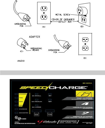
Grounding Methods
9.control panel
SC-600A
• 6 •

SC-1000A
SC-1200A
SSC-1000A
• 7 •
SSC-1500A
9.1DIGITAL DISPLAY
The Digital Display gives a digital indication of % of charge or voltage, depending on the Display Mode chosen.
DISPLAY MODE BUTTON
Use this button to set the function of the Digital Display to one of the following:
•Battery % – The Digital Display shows an estimated charge percent of the battery connected to the charger battery clamps.
•Voltage – The Digital Display shows the voltage at the charger battery clamps in DC volts.
9.2CHARGE RATE BUTTON
Use this button to set the maximum charge rate to one of the following:
•2A Slow Charge Rate – Intended for charging small batteries such as those commonly used in garden tractors, snow mobiles and motorcycles.
•4A, 6A, 8A Medium Charge Rate – Use for charging automotive, marine and deep-cycle batteries. Not intended for industrial applications.
•10A, 12A, 15A Fast Charge Rate - Use for charging automotive and light truck batteries. Not intended for industrial applications.
9.3BATTERY TYPE BUTTON
Use this button to set the type of battery to be charged.
•6V – This battery type is usually used in garden tractors, motorcycles and antique vehicles.
•12V – This battery type is usually used in automotive, marine and deep cycle situations.
•8 •

•Regular (Standard) – This battery type is usually used in cars, trucks and motorcycles. These batteries have vent caps and are often marked “Low Maintenance” or “Maintenance-free”. This type of battery is designed to deliver quick bursts of energy (such as starting engines) and have a greater plate count. The plates will also be thinner and have somewhat different material composition. Regular batteries should not be used for deep cycle applications.
•Deep-Cycle – Deep-cycle batteries are usually marked as “Deep-Cycle” or “Marine”. Deep-cycle batteries are usually larger than the other types. This type of battery has less instant energy but somewhat greater long-term energy delivery than regular batteries. Deep cycle batteries have thicker plates and can survive a number of discharge cycles.
•AGM – The Absorbed Glass Matt construction allows the electrolyte to be suspended in close proximity with the plate’s active material. In theory, this enhances both the discharge and recharge efficiency. Actually, the AGM batteries are a variant of Sealed VRLA (valve regulated lead acid) batteries. Popular uses include high performance engine starting, power sports, deep cycle, solar and storage battery.
•GEL – The Gel Cell is similar to the AGM style because the electrolyte is suspended, but different because technically the AGM battery is still considered to be a wet cell. The electrolyte in a GEL cell has a silica additive that causes it to set up or stiffen. The recharge voltages on this type of cell are lower than the other styles of lead acid battery. This is probably the most sensitive cell in terms of adverse reactions to
over-voltage charging. Gel Batteries are best used in VERY DEEP cycle application and may last a bit longer in hot weather applications. If the incorrect battery charger is used on a Gel Cell battery, poor performance and premature failure is certain.
10.Assembly Instructions
No assembly required.
11.operating instructions
11.1Overview
1.Connect the battery and AC power following the precautions listed in sections 6 and 7.
2.Select the appropriate battery type and charge rate for your battery.
11.2Charging
If the charger does not detect a properly connected battery, the CON-
NECTED (red) LED will not light until such a battery is detected. Charging will not begin while the CONNECTED (red) LED is not on. When charging begins, the CHARGING (yellow) LED will be lit.
•9 •
11.3Battery Percent and Charge Time: This charger adjusts the charging time in order to charge the battery completely, efficiently and safely. The microprocessor automatically performs the necessary
functions. This section includes guidelines that can be used to estimate charging times.
The duration of the charging process depends on three factors:
•Battery State – If a battery has only been slightly discharged, it can be charged in less than a few hours. The same battery could take up to 10 hours if very weak. With Models SC-1200A, SSC-1000A and SSC-1500A the battery state can be estimated by using the built-in voltage tester. The lower the reading the longer charging will take.
•Battery Rating – A higher rated battery will take longer to charge than a lower rated battery under the same conditions. A battery is rated in ampere hours (AH), reserve capacity (RC) and cold cranking amps (CCA). The lower the rating, the quicker the battery will charge.
•Charge Rate – The charge rate is measured in amps. The 2A rate is for charging smaller batteries such as those used for motorcycles and garden tractors. Such batteries should not be charged using the higher rates. The 4A, 6A and 8A rates are for charging automotive, marine and deep-cycle batteries. The 10A, 12A and 15A rates are for charging automotive and light truck batteries. All charging modes will decrease the charge rate as the battery approaches maximum charge. After the charging process has started, the digital display can be used to determine charging progress by selecting the BATTERY % mode. (Models SC-1200A, SSC-1000A and SSC-1500A)
There are some important facts to keep in mind when charging a battery.
•When the display indicates 77% charged, the battery has been charged enough to start most vehicles.
•When the battery is fully charged, the display will indicate 100% charged.
•The battery % shown in tester mode is an estimate based on the battery voltage.
•The battery % shown in charger mode is an estimate of the relative charge in the battery compared to the charge it should have if the charging process is allowed to complete and can be used to estimate the relative charge time. The lower the % shown the longer the charge time for a given battery.
•The battery % shown in charger mode is an indication of the relative progress of the charging process. The higher the battery % displayed, the less charge time remains.
•The more a battery is discharged, the faster it absorbs charge from a charger. That means that the battery % increases faster at the beginning of the charging process than at the end. In other words, it takes longer for the battery to absorb the last few percents of charge than the first several percents.
•10 •
11.4Automatic Charging Mode: When a charge rate is selected, the charger is set to perform an automatic charge. When an automatic charge is performed, the charger switches to the maintain mode (see below) automatically after the battery is charged.
11.5Aborted Charge
If charging can not be completed normally, charging will abort. When charging aborts, the charger’s output is shut off and the CONNECTED
(red) LED will blink. In that state, the charger ignores all buttons. To reset after an aborted charge, either disconnect the battery or unplug the charger.
11.6Desulfation Mode: If the battery is left discharged for an extended period of time, it could become sulfated and not accept a normal charge. If the charger detects a sulfated battery, the charger will switch to a special mode of operation designed for such batteries. Activation of the special desulfation mode is indicated by the CHARGING (yellow) LED blinking.
If successful, normal charging will resume after the battery is desulfated.
The CHARGING (yellow) LED will then stop blinking and stay lit. Desulfation could take up to 10 hours. If desulfation fails, charging will abort and the
CONNECTED (red) LED will blink.
11.7Completion Of Charge: Charge completion is indicated by the
CHARGED (green) LED. When lit, the charger has stopped charging and switched to the Maintain Mode of operation. On Models SSC-1000A and SSC-1500A, if the DEEP CYCLE battery type is selected, the CHARGED
(green) LED comes on when the battery is charged enough for normal use.
11.8Maintain Mode: When the CHARGED (green) LED is lit, the charger has started Maintain Mode. In this mode, the charger keeps the battery fully charged by delivering a small current, when necessary. The voltage is maintained at a level determined by the BATTERY TYPE selected.
11.9Using the Battery Voltage Tester
(Models SC-1200A, SSC-1000A and SSC-1500A only) Overview
This battery charger has a built-in voltmeter to test your battery’s state of charge. The charger does not have a built in load tester. As such, a recently charged battery could have a temporarily high voltage due to what is known as “surface charge”. The voltage of such a battery will gradually drop during the period immediately after the charging system is
disengaged. Consequently, the tester could display inconsistent values for such a battery. For a more accurate reading, the surface charge should be removed by temporarily creating a load on the battery, such as by turning on lights or other accessories for a couple of minutes before you read the display. Read it a couple of minutes after you have shut the headlights off.
Testing Sequence: There are four basic steps required to test the battery state of charge:
•11 •
 Loading...