


TECHNICAL DATA
&
SERVICE MANUAL
XS1852 / C1852, CL1852
FILE NO.
SPLIT SYSTEM AIR CONDITIONER
INDOOR MODEL No. |
PRODUCT CODE No. |
OUTDOOR MODEL No. |
PRODUCT CODE No. |
|
XS1852 |
854 016 13 |
C1852 |
852 068 35 |
|
CL1852 |
852 068 36 |
|||
|
|
|||
|
|
|
|
Indoor Unit |
Outdoor Unit |
XS1852 |
C1852 |
|
CL1852 |
85464849179000 |
REFERENCE NO. SM830079 |

 Important
Please Read Before Starting
This air conditioning system meets strict safety and operating standards. As the installer or service person, it is an important part of your job to install or service the system so it operates safely and efficiently.
For safe installation and trouble-free operation, you must :
ÚCarefully read this instruction booklet before beginning.
ÚFollow each installation or repair step exactly as shown.
ÚObserve all local, state, and national electrical codes.
ÚPay close attention to all warning and caution notices given in this manual.
This symbol refers to a hazard or unsafe practice which can result in severe personal injury or death.
This symbol refers to a hazard or
CAUTION unsafe practice which can result in personal injury or product or
property damage.
If Necessary, Get Help
These instructions are all you need for most installation sites and maintenance conditions. If you require help for a special problem, contact our sales/service outlet or your certified dealer for additional instructions.
In Case of Improper Installation
The manufacturer shall in no way be responsible for improper installation or maintenance service, including failure to follow the instructions in this document.
SPECIAL PRECAUTIONS
When Wiring
……………………………………………………………………
ELECTRICAL SHOCK CAN CAUSE SEVERE
PERSONAL INJURY OR DEATH. ONLY A
QUALIFIED, EXPERIENCED ELECTRICIAN
SHOULD ATTEMPT TO WIRE THIS SYSTEM.
•Do not supply power to the unit until all wiring and tubing are completed or reconnected and checked.
•Highly dangerous electrical voltages are used in this system. Carefully refer to the wiring diagram and these instructions when wiring. Improper connections and inadequate grounding can cause accidental injury or death.
•Ground the unit following local electrical codes.
•Connect all wiring tightly. Loose wiring may cause overheating at connection points and a possible fire hazard.
When Transporting
……………………………………………………………………
Be careful when picking up and moving the indoor and outdoor units. Get a partner to help, and bend your knees when lifting to reduce strain on your back. Sharp edges or thin aluminum fins on the air conditioner can cut your fingers.
When Installing
……………………………………………………………………
…In a Room
Properly insulate any tubing run inside a room to prevent
“sweating” that can cause dripping and water damage to walls and floors.
…In Moist or Uneven Locations
Use a raised concrete pad or concrete blocks to provide a solid, level foundation for the outdoor unit. This prevents water damage and abnormal vibration.
…In an area with High Winds
Securely anchor the outdoor unit down with bolts and a metal frame. Provide a suitable air baffle.
…In a Snowy Area (for Heat Pump-type Sys-tems)
Install the outdoor unit on a raised platform that is higher than drifting snow. Provide snow vents.
When Connecting Refrigerant Tubing
……………………………………………………………………
•Ventilate the room well, in the event that refrigerant gas leaks during the installation. Be careful not to allow contact of the refrigerant gas with a flame as this will cause the generation of poisonous gas.
•Keep all tubing runs as short as possible.
•Use the flare method for connecting tubing.
•Apply refrigerant lubricant to the matching surfaces of the flare and union tubes before connecting them, then tighten the nut with a torque wrench for a leak-free connection.
•Check carefully for leaks before starting the test run.
NOTE
Depending on the system type, liquid and gas lines may be either narrow or wide. Therefore, to avoid confusion the refrigerant tubing for your particular model is specified as either
“narrow” or “wide” rather than as “liquid” or “gas”.
When Servicing
……………………………………………………………………
•Turn the power OFF at the main power box (mains) before opening the unit to check or repair electrical parts and wiring.
•Keep your fingers and clothing away from any moving parts.
•Clean up the site when installation is finished. Check that no metal scraps or bits of wiring have been left inside the unit.
CAUTION
•Ventilate any enclosed areas when installing or testing the refrigeration system. Contact of refrigerant gas with fire or heat can produce poisonous gas.
•Confirm after installation that no refrigerant gas is leaking. If the gas comes in contact with a burning stove, gas water heater, electric room heater or other heat source, it can cause the generation of poisonous gas.
SM830079
– 2 –

Table of Contents
1. |
OPERATING RANGE ....................................................................................... |
5 |
|
2. |
SPECIFICATIONS ............................................................................................ |
6 |
|
|
(1) |
Unit Specifications ...................................................................................... |
6 |
|
(2) |
Major Component Specifications ................................................................ |
8 |
|
|
(A) Indoor Unit ............................................................................................ |
8 |
|
|
(B) Outdoor Unit .......................................................................................... |
9 |
|
(3) |
Other Component Specifications .............................................................. |
10 |
|
|
(A) Indoor Unit .......................................................................................... |
10 |
|
|
(B) Outdoor Unit ........................................................................................ |
11 |
3. |
DIMENSIONAL DATA..................................................................................... |
12 |
|
|
(1) |
Indoor Unit ................................................................................................ |
12 |
|
(2) |
Outdoor Unit.............................................................................................. |
13 |
4. |
PERFORMANCE CHARTS ............................................................................ |
14 |
|
|
(1) |
Operating Current ..................................................................................... |
14 |
5. |
AIR THROW DISTANCE CHART ................................................................... |
15 |
|
6. |
REFRIGERANT FLOW DIAGRAM ................................................................. |
16 |
|
7. |
INSTALLATION INSTRUCTIONS .................................................................. |
17 |
|
8. |
ELECTRICAL DATA ....................................................................................... |
22 |
|
9. |
ELECTRICAL WIRING DIAGRAMS ............................................................... |
23 |
|
|
(1) |
Indoor Unit ................................................................................................ |
23 |
|
(2) |
Outdoor Unit.............................................................................................. |
25 |
10. |
PROCESSES AND FUNCTIONS.................................................................. |
27 |
|
|
(1) |
Room Temperature Control ...................................................................... |
27 |
|
(2) |
Freeze Prevention ..................................................................................... |
28 |
|
(3) |
Drain Pump Control .................................................................................. |
28 |
|
(4) |
Outdoor Fan Speed Control ...................................................................... |
29 |
11. |
SERVICE PROCEDURES .............................................................................. |
30 |
|
|
(1) |
Troubleshooting ........................................................................................ |
30 |
|
(2) |
A Sensor is Defective ................................................................................ |
40 |
|
(3) |
Operation of Major Electrical Parts ........................................................... |
40 |
|
(4) |
Checking the Electrical Components ........................................................ |
41 |
SM830079
– 3 –

Introduction: Read Me First!
This manual will help you understand and service the air conditioner. To help you find the information you need, we have divided it into 5 main sections. Each section is divided into chapters with charts, tables and explanations to help you find and repair problems.
Section 1: Specifications, tells you about the physical and electrical make up of the unit, as well as its heating and cooling capacities. Look in this section to find the correct values for components and functions.
Section 2: Processes and Functions, explains each different part of the cooling and heating cycle, and how each control function reacts to changing conditions to keep the room at the set temperature range.
Section 3: Electrical Data, which has fold-out schematic and wiring diagrams so you can find the parts you need to check when something is wrong, and see how they should be connected.
Section 4: Service Procedures, has two main parts, a diagnostic chapter to help you find the specific component to replace or adjust, and a chapter with specific procedures and values to guide you in checking the electrical components in the unit.
HOW TO USE THIS MANUAL
You can use this manual both as a reference to find specific information about the capacity, functions and construction of this unit, and as a source of information to help you set up and maintain the unit.
When this unit is not working properly, and the cause is not known, you can use the procedures in Section 3: Servicing Procedures to find the problem, fix it, and restore the unit to its proper functioning.
This air conditioner has many helpful self diagnostic features to help you identify problem areas quickly.
So you will be ready when a problem happens, we suggest you look this manual over and become familiar with it by following these steps:
1.Look at the TABLE OF CONTENTS to get an idea of what is in this manual and where to find it.
2.Look at the chapter about TROUBLE SHOOTING, so you are familiar with the way the flow charts work. They are designed to guide you quickly through the possible causes for each kind of problem that is likely to happen to the Unit. Particularly read the introduction to this section, and the parts about the self-diagnosis and error codes which show on the display.
3.Look at the chapter about CHECKING ELECTRICAL COMPONENTS. You already know about most of these procedures. This chapter gives you the specific values and methods for these components. If you don’t know some of these procedures, you can easily learn them here.
4.Read the Instruction Manual! The Instruction Manual is included here because it helps you help the user to set the temperature controls properly and know how to take care of any simple problems that may happen, as well as know when to call for service. The Instruction Manual also has illustrations, care, and installation information not found in the rest of the service manual. It is short, and if you read it carefully, you will be able to answer the customers questions easily, and also know the most efficient ways for setting times and temperatures.
Please use this manual to make your work easier, keep the air conditioner functioning well, and keep your customers satisfied.
SM830079
– 4 –

1. OPERATING RANGE
XS1852 / C1852
Temperature |
Indoor Air Intake Temp. |
Outdoor Air Intake Temp. |
|
Maximum |
95 °F DB / 71 °F WB |
115 |
°F DB |
Minimum |
67 °F DB / 57 °F WB |
67 |
°F DB |
|
|
|
|
XS1852 / CL1852
Temperature |
Indoor Air Intake Temp. |
Outdoor Air Intake Temp. |
|
Maximum |
95 °F DB / 71 °F WB |
115 |
°F DB |
|
|
|
|
Minimum |
67 °F DB / 57 °F WB |
0 |
°F DB |
|
|
|
|
SM830079
– 5 –

2. SPECIFICATIONS
(1) Unit Specifications
|
MODEL No. |
|
Indoor Unit |
|
|
XS1852 |
||
|
|
|
|
|
|
|
||
|
|
|
Outdoor Unit |
|
|
C1852 , CL1852 |
||
|
POWER SOURCE |
|
|
|
230 - 208 V / 1 Phase / 60 Hz |
|||
|
|
|
|
|
|
|
||
|
PERFORMANCE |
|
|
|
|
Cooling |
||
|
|
|
|
|
|
|
|
|
|
Capacity |
|
BTU / h |
18,000 |
|
17,500 |
||
|
|
|
|
|
|
|
|
|
|
|
|
|
|
kW |
5.27 |
|
5.13 |
|
|
|
|
|
|
|
||
|
Air circulation (Hi) |
|
cu.ft. / min. |
540 |
|
510 |
||
|
|
|
|
|
|
|
||
|
Moisture removal (High) |
|
Pints / h |
5.5 |
|
5.4 |
||
|
|
|
|
|
|
|
|
|
|
ELECTRICAL RATINGS |
|
|
|
|
|
|
|
|
|
|
|
|
|
|
|
|
|
Voltage rating |
|
|
VAC |
230 |
|
208 |
|
|
|
|
|
|
|
|
|
|
|
Available voltage range |
|
|
VAC |
|
187 - 253 |
||
|
|
|
|
|
|
|
|
|
|
Running amperes* |
|
|
A |
8.2 |
|
8.77 |
|
|
|
|
|
|
|
|
|
|
|
Max. running amperes** |
|
|
A |
9.7 |
|
10.6 |
|
|
|
|
|
|
|
|
|
|
|
Power input |
|
|
W |
1,780 |
|
1,740 |
|
|
|
|
|
|
|
|
|
|
|
Power factor |
|
|
% |
97 |
|
98 |
|
|
|
|
|
|
|
|
||
|
S.E.E.R |
|
BTU / Wh |
10.6 |
|
10.6 |
||
|
|
|
|
|
|
|
|
|
|
Max. starting amperes |
|
|
A |
44.7 |
|
44.6 |
|
|
|
|
|
|
|
|
|
|
|
Maximum fuse size |
|
|
A |
|
20 |
||
|
|
|
|
|
|
|
|
|
|
FEATURES |
|
|
|
|
|
|
|
|
|
|
|
|
|
|
||
|
Controls |
|
|
|
|
Microprocessor |
||
|
|
|
|
|
|
|||
|
Low ambient control |
|
|
|
Built-in 0 °F (Only for CL1852) |
|||
|
|
|
|
|
|
|||
|
Timer |
|
|
|
ON / OFF 24-hours & Program |
|||
|
|
|
|
|
|
|||
|
Fan speed Indoor / Outdoor |
|
|
|
3 and Automatic control / 1 (3 : CL1852) |
|||
|
|
|
|
|
||||
|
Air deflection |
Horizontal / Vertical |
|
– / Automatic |
||||
|
|
|
|
|
|
|
||
|
Air filter |
|
|
|
|
Washable, easy access |
||
|
|
|
|
|
|
|
||
|
Remote controller (Accessory) |
|
|
|
|
RCS - 5PS4U |
||
|
|
|
|
|
|
|
||
|
Refrigerant control |
|
|
|
|
Capillary tube |
||
|
|
|
|
|
|
|
||
|
Refrigerant tubing connections |
|
|
|
|
Flare type |
||
|
|
|
|
|
|
|||
|
Drain pump (drain connection) |
|
|
|
Max. head 9-27/32 in. above drain connection |
|||
|
|
|
|
|
|
|
||
|
Compressor |
|
|
|
|
Rotary |
||
|
|
|
|
|
|
|||
|
Operation sound |
|
Indoor - Hi / Me / Lo |
dB - A |
|
37 / 35 / 31 |
||
|
|
|
Outdoor - Hi |
dB - A |
|
52 |
||
|
|
|
|
|
|
|
|
|
|
REFRIGERANT TUBING |
|
|
|
|
|
|
|
|
|
|
|
|
|
|
||
|
Limit of tubing length |
|
ft. |
(m) |
|
65 (20) |
||
|
|
|
|
|
|
|||
|
Limit of tubing length at shipment |
ft. |
(m) |
|
33 (10) |
|||
|
|
|
|
|
|
|||
|
Limit of elevation difference |
|
ft. |
(m) |
Outdoor unit is higher than indoor unit: 23 (7) |
|||
|
between the two units |
|
|
|
Outdoor unit is lower than indoor unit: 23 (7) |
|||
|
|
|
|
|
|
|||
|
Refrigerant tube |
|
Narrow tube |
in. (mm) |
|
1 / 4 (6.35) |
||
|
outer diameter |
|
Wide tube |
in. (mm) |
|
5 / 8 (15.88) |
||
|
|
|
|
|
|
|||
|
Refrigerant amount at shipment |
lbs. (kg) |
|
R22 : 4.45 (2.02) |
||||
|
|
|
|
|
|
|
|
|
SM830079
– 6 –

2. SPECIFICATIONS
(1)Unit Specifications
|
DIMENSIONS & WEIGHT |
|
|
Indoor unit |
Outdoor unit |
||
|
|
|
|
|
|
|
|
|
Unit dimensions |
Height |
in. (mm) |
9-27/32 |
(250) |
24-19/32 |
(625) |
|
|
|
|
|
|
|
|
|
|
Width |
in. (mm) |
29-29/32 |
(760) |
32-21/32 |
(880) |
|
|
|
|
|
|
|
|
|
|
Depth |
in. (mm) |
29-29/32 |
(760) |
12-19/32 |
(320) |
|
|
|
|
|
|
|
|
|
Net weight |
|
lbs. (kg) |
49 |
(22) |
104 |
(47) |
|
|
|
|
|
|
|
|
|
Indoor grille dimensions |
Height |
in. (mm) |
3-1/16 |
(78) |
|
|
|
|
|
|
|
|
|
|
|
|
Width |
in. (mm) |
33-27/32 |
(860) |
|
|
|
|
|
|
|
|
|
|
|
|
Depth |
in. (mm) |
33-27/32 |
(860) |
|
|
|
|
|
|
|
|
|
|
|
Net weight |
|
lbs. (kg) |
11 |
(5) |
|
|
|
|
|
|
|
|
|
|
|
Indoor Unit |
Height |
in. (mm) |
11-6/32 |
(284) |
27-30/32 |
(710) |
|
|
|
|
|
|
|
|
|
Package dimensions |
Width |
in. (mm) |
32-14/32 |
(824) |
40-18/32 |
(1,030) |
|
|
|
|
|
|
|
|
|
|
Depth |
in. (mm) |
32-25/32 |
(833) |
16-6/32 |
(411) |
|
|
|
|
|
|
|
|
|
Shipping weight |
|
lbs. (kg) |
57 |
(26) |
112 |
(51) |
|
|
|
|
|
|
|
|
|
Shipping volume |
|
cu. ft. (m3) |
6.9 |
(0.195) |
10.3 |
(0.301) |
|
Indoor grille |
Height |
in. (mm) |
4-3/32 |
(104) |
|
|
|
|
|
|
|
|
|
|
|
Package dimensions |
Width |
in. (mm) |
38-2/32 |
(967) |
|
|
|
|
|
|
|
|
|
|
|
|
Depth |
in. (mm) |
39-11/32 |
(999) |
|
|
|
|
|
|
|
|
|
|
|
Shipping weight |
|
lbs. (kg) |
18 |
(8) |
|
|
|
|
|
|
|
|
|
|
|
Shipping volume |
|
cu. ft. (m3) |
3.5 |
(0.100) |
|
|
DATA SUBJECT TO CHANGE WITHOUT NOTICE
Cooling :
Rating conditions (*) : Indoor air temperature 80 °F DB / 67 °F WB, Outdoor air temperature 95 °F DB / 75 °F WB Full load conditions (**) : Indoor air temperature 80 °F DB / 67 °F WB, Outdoor air temperature 115 °F DB
SM830079
– 7 –

2. SPECIFICATIONS
(2)Major Component Specifications
(A)Indoor Unit
|
MODEL No. |
|
|
|
|
|
XS1852 |
|
|
|
|||
|
|
|
|
|
|
|
|
|
|||||
|
Source |
|
|
|
|
230 - 208 V / 1 phase / 60 Hz |
|
|
|||||
|
|
|
|
|
|
|
|
|
|
|
|||
|
Remote controller (Accessory) |
|
|
|
|
|
RCS - 5PS4U |
|
|
|
|||
|
|
|
|
|
|
|
|
|
|
|
|||
|
Controller P. C. B Ass'y |
|
|
|
|
|
CR - TS2432 |
|
|
|
|||
|
|
|
|
|
|
|
|
|
|
|
|||
|
Control circuit fuse |
|
|
|
|
|
250 V, 3 A |
|
|
|
|||
|
|
|
|
|
|
|
|
|
|
|
|||
|
Switch Ass'y |
|
|
|
|
|
SW - X363GS |
|
|
|
|||
|
|
|
|
|
|
|
|
|
|
||||
|
Fan (Number … diameter) |
in. |
(mm) |
|
|
Turbo (1…19-9/32 (490)) |
|
|
|
||||
|
|
|
|
|
|
|
|
|
|
|
|
|
|
|
Fan motor |
|
|
|
|
|
|
|
|
|
|
|
|
|
|
|
|
|
|
|
|
|
|
|
|
||
|
Model |
|
|
|
|
|
SFG6X - 41A5P |
|
|
|
|||
|
|
|
|
|
|
|
|
|
|||||
|
Source |
|
|
|
|
230 - 208 V / 1 phase / 60 Hz |
|
|
|||||
|
|
|
|
|
|
|
|
|
|
|
|||
|
No. of pole … r.p.m. (230 V, High) |
|
rpm |
|
|
|
6 … 451 |
|
|
|
|||
|
|
|
|
|
|
|
|
|
|
|
|
|
|
|
Nominal output |
|
W |
|
|
|
|
40 |
|
|
|
|
|
|
|
|
|
|
|
|
|
|
|
|
|
|
|
|
Coil resistance |
|
Ω |
BRW - |
WHT |
: |
114.0 |
, |
ORG - |
YEL |
: |
66.4 |
|
|
(Ambient temperature 68 °F) |
|
|
WHT - |
VLT |
: |
23.9 |
, |
WHT - |
PNK |
: |
77.4 |
|
|
|
|
|
|
VLT - |
ORG |
: |
12.4 |
, |
YEL - |
BLK |
: |
82.1 |
|
|
|
|
|
|
|
|
|
|
|
|
|
|
|
Safety device |
|
|
|
|
|
|
|
|
|
|
|
|
|
|
|
|
|
|
|
|
|
|
|
|
|
|
|
|
Operating temperature |
Open |
°F |
|
|
|
266 |
± |
14.4 |
|
|
|
|
|
|
|
|
|
|
|
|
|
|
|
|
|
|
|
|
Close |
°F |
|
|
|
174.2 |
± |
27 |
|
|
|
|
|
|
|
|
|
|
|
|
|
|
|
||
|
Run capacitor |
VAC, |
μF |
|
|
|
440 V , 3.5 μF |
|
|
|
|||
|
|
|
|
|
|
|
|
|
|
|
|
|
|
|
Heat exchanger |
|
|
|
|
|
|
|
|
|
|
|
|
|
|
|
|
|
|
|
|
|
|||||
|
Coil |
|
|
|
Aluminum plate fin / Copper tube |
|
|
||||||
|
|
|
|
|
|
|
|
|
|
|
|||
|
Rows … Fins per inch |
|
|
|
|
|
2 … 14.9 |
|
|
|
|||
|
|
|
|
|
|
|
|
|
|
|
|||
|
Face area |
ft.2 |
(m2) |
|
|
|
3.2 (0.297) |
|
|
|
|||
|
Panel |
|
|
|
|
|
|
|
|
|
|
|
|
|
|
|
|
|
|
|
|
|
|
|
|
||
|
Model No. |
|
|
|
|
|
PNR - XS2432 |
|
|
|
|||
|
|
|
|
|
|
|
|
|
|
|
|||
|
Indicator Lamp Ass'y |
|
|
|
|
|
IND - XS2432 |
|
|
|
|||
|
|
|
|
|
|
|
|
|
|
|
|||
|
Auto louver motor |
|
|
|
|
|
MT8 - 3C |
|
|
|
|||
|
|
|
|
|
|
|
|
|
|
|
|||
|
Auto louver motor … Rated |
V, W, |
rpm |
|
|
|
240 VAC , 3 W , 3 rpm |
|
|
|
|||
|
|
|
|
|
|
|
|
|
|
|
|||
|
Coil resistance (Ambient temperature 77 °F) |
|
Ω |
|
|
|
16,430 Ω ± 8 % |
|
|
|
|||
|
|
|
|
|
|
|
|
|
|
|
|
|
|
DATA SUBJECT TO CHANGE WITHOUT NOTICE
SM830079
– 8 –

2. SPECIFICATIONS
(2)Major Component Specifications
(B)Outdoor Unit
|
MODEL No. |
|
|
C1852 |
|
|
CL1852 |
||
|
|
|
|
|
|
|
|||
|
Source |
|
|
230 - 208 V / 1 phase / 60 Hz |
|||||
|
|
|
|
|
|
|
|
|
|
|
Controller P.C.B. Ass'y |
|
|
— |
|
|
POW - CL125 |
||
|
|
|
|
|
|
|
|
||
|
|
Control circuit fuse |
|
|
250 VAC, 5 A |
||||
|
|
|
|
|
|
|
|
||
|
Compressor |
|
|
Rotary (Hermetic) |
|||||
|
|
|
|
|
|
|
|
||
|
|
Model |
|
|
C - R132H6D |
||||
|
|
|
|
|
|
|
|
||
|
|
Source |
|
|
230 - 208 V / 1 phase / 60 Hz |
||||
|
|
|
|
|
|
|
|
||
|
|
Nominal output |
|
W |
1,300 |
||||
|
|
|
|
|
|
|
|
|
|
|
|
Compressor oil |
|
cc |
500 |
|
|||
|
|
|
|
|
|
|
|
||
|
|
Coil resistance (Ambient temperature 77 °F) |
|
Ω |
C – R : 1.442 , C – S : 2.567 |
||||
|
|
|
|
|
|
|
|
||
|
|
Safety device |
|
|
Internal type |
||||
|
|
|
|
|
|
|
|
|
|
|
|
Overload relay models |
|
|
|
— |
|
||
|
|
|
|
|
|
|
|
|
|
|
|
Operating temperature |
Open |
°F |
311 |
± |
9 |
||
|
|
|
|
|
|
|
|
||
|
|
|
|
Close |
°F |
188 ± 20 |
|||
|
|
|
|
|
|
|
|
|
|
|
|
Operating ampere (at 77 °F) |
|
A |
|
— |
|
||
|
|
|
|
|
|
|
|
||
|
|
Run capacitor |
VAC, |
μF |
400 V, 35 μF |
||||
|
|
|
|
|
|
|
|
|
|
|
|
Crank case heater |
VAC, |
W |
— |
|
|
230 V, 20 W |
|
|
|
|
|
|
|
|
|
||
|
Refrigerant amount charged at shipment |
lbs. |
(kg) |
R22 : 3.59 (1.63) |
|||||
|
|
|
|
|
|
|
|||
|
Fan |
|
|
Propeller |
|||||
|
|
|
|
|
|
|
|
||
|
|
Number...diameter |
in. |
(mm) |
1 ... 16 - 17/32 (ø420) |
||||
|
|
|
|
|
|
|
|
|
|
|
Fan motor |
|
|
|
|
|
|
||
|
|
|
|
|
|
|
|
|
|
|
|
Model |
|
|
KFG6 - 51E6P ... 1 |
|
|
KFG6T - 51B6P ... 1 |
|
|
|
|
|
|
|
|
|
||
|
|
Source |
|
|
230 - 208 V / 1 phase / 60 Hz |
||||
|
|
|
|
|
|
|
|
||
|
|
No. of pole ..... rpm (230 V, High) |
|
|
C type : 6 ... 830 , CL type : 6 ... 813 |
||||
|
|
|
|
|
|
|
|
|
|
|
|
Nominal output |
|
|
W |
|
50 |
|
|
|
|
|
|
|
|
|
|
|
|
|
|
Coil resistance |
|
|
Ω |
BRN – WHT : 102 |
, |
WHT – PNK : 199 |
|
|
|
(Ambient temperature 68 °F) |
|
|
|
|
|
|
|
|
|
|
|
|
|
|
|
||
|
|
Safety device |
|
|
Internal type |
||||
|
|
|
|
|
|
|
|
|
|
|
|
Operating temperature |
Open |
°F |
266 |
± |
14 |
||
|
|
|
|
|
|
|
|
|
|
|
|
|
|
Close |
°F |
174 |
± |
27 |
|
|
|
|
|
|
|
|
|
||
|
|
Run capacitor |
VAC, |
μF |
440 V, 2 μF |
||||
|
|
|
|
|
|
|
|
|
|
|
Heat exchange |
|
|
|
|
|
|
||
|
|
|
|
|
|
|
|
||
|
|
Coil |
|
|
Aluminum plate fin / Copper tube |
||||
|
|
|
|
|
|
|
|
||
|
|
Rows ..... Fins per inch |
|
|
2 ... 1/16 (1.6) |
||||
|
|
|
|
|
|
|
|
||
|
|
Face area |
ft.2 |
(m2) |
4.0 (0.372) |
||||
DATA SUBJECT TO CHANGE WITHOUT NOTICE
SM830079
– 9 –

2. SPECIFICATIONS
(3)Other Component Specifications
(A)Indoor Unit
|
MODEL No. |
|
|
|
|
|
XS1852 |
|
|
|
|
|
Power Transformer |
|
|
|
|
|
ATR – I104A |
|
|
|
|
|
|
|
|
|
|
|
|
|
|
|
|
|
Rated |
|
Primary |
|
|
|
AC 220 V, 60 Hz |
|
|
|
|
|
|
|
|
|
|
|
|
|
|
|
|
|
|
|
Secondary |
|
|
|
10.6 V, 0.93 A |
|
|
|
|
|
|
|
|
|
|
|
|
|
|
|
|
|
|
|
Capacity |
|
|
|
9.85 VAC |
|
|
|
|
|
|
|
|
|
|
|
|
|
|
|
|
|
Coil resistance |
|
Ω |
WHT - |
WHT |
: 101 , BRN - |
BRN |
: |
0.42 |
||
|
(Ambient temprature 77 °F) |
||||||||||
|
|
|
|
|
|
|
|
|
|||
|
|
|
|
|
|
|
|
|
|
||
|
Thermistor cut off temperature |
°F |
|
|
|
266 |
|
|
|
||
|
|
|
|
|
|
|
|
|
|
|
|
|
Thermistor (Coil sensor) |
|
|
|
|
|
PBC - 41E - S26 |
|
|
|
|
|
|
|
|
|
|
|
|
||||
|
Coil resistance |
|
kΩ |
14 °F : 23.7 |
, |
41 |
°F : 12.1 |
||||
|
|
|
|
|
23 |
°F : 18.8 |
, |
50 |
°F : |
9.7 |
|
|
|
|
|
|
32 |
°F : 15.0 |
, |
59 |
°F : |
8.0 |
|
|
|
|
|
|
|
|
|
|
|
||
|
Thermistor (Room or coil sensor) |
|
|
|
|
KTEC - 35 - S6 |
|
|
|
||
|
|
|
|
|
|
|
|
|
|||
|
Coil resistance |
|
kΩ |
32 °F : 16.5 |
, |
104 |
°F : |
2.7 |
|||
|
|
|
|
|
41 |
°F : 12.8 |
, |
113 |
°F : |
2.2 |
|
|
|
|
|
|
50 |
°F : 10.0 |
, |
122 |
°F : |
1.8 |
|
|
|
|
|
|
68 |
°F : |
6.3 |
, |
131 |
°F : |
1.5 |
|
|
|
|
|
86 |
°F : |
4.0 |
, |
|
|
|
|
|
|
|
|
|
|
|
|
|
|
|
|
Reray |
|
|
|
|
|
G7L - 2A - TUB |
|
|
|
|
|
|
|
|
|
|
|
|
|
|
|
|
|
Coil rated |
|
V |
|
|
|
AC 220 - 240 V |
|
|
|
|
|
|
|
|
|
|
|
|
|
|
|
|
|
Contact rating |
|
V, A |
|
|
|
277 VAC, 25A |
|
|
|
|
|
|
|
|
|
|
|
|
|
|
|
|
|
Drain pump |
|
|
|
|
|
WP20SL - 21 |
|
|
|
|
|
|
|
|
|
|
|
|
|
|
|
|
|
Rated |
|
|
|
|
|
AC 200 V, 14.7 W |
|
|
|
|
|
|
|
|
|
|
|
|
|
|
|
|
|
Float switch |
|
|
|
|
|
FS - 0218 - 102 |
|
|
|
|
|
|
|
|
|
|
|
|
|
|
||
|
MAX Rated (Contact rated) |
|
|
|
|
AC 200 V, 50 W |
|
|
|
||
|
|
|
|
|
|
|
|
|
|
|
|
|
Switch Ass'y |
|
|
|
|
|
SW - X363GS |
|
|
|
|
|
|
|
|
|
|
|
|
|
|
|
|
|
Indicator Lamp Ass'y |
|
|
|
|
|
IND - XS2432 |
|
|
|
|
|
|
|
|
|
|
|
|
|
|
|
|
|
Synchronized Motor |
|
|
|
|
|
MT8 - 3C |
|
|
|
|
|
|
|
|
|
|
|
|
|
|
|
|
DATA SUBJECT TO CHANGE WITHOUT NOTICE
SM830079
– 10 –
2.SPECIFICATIONS
(3)Other Component Specifications
(B)Outdoor Unit
|
MODEL No. |
|
|
CL1852 |
|
|
|
|
|
Compressor Motor Magnetic Contactor |
|
– |
|
|
|
||
|
|
|
|
|
|
|
|
|
|
|
Coil rated |
|
|
– |
|
|
|
|
|
|
|
|
|
|
|
|
|
|
Coil resistance (at 77 °F) |
kΩ |
|
– |
|
|
|
|
|
|
|
|
|
|
|
|
|
|
Contact rated (Main) |
|
|
– |
|
|
|
|
|
|
|
|
|
|
|
|
|
|
Contact rated (Auxiliary) |
|
|
– |
|
|
|
|
|
|
|
|
|
|
|
|
|
Power Transformer |
|
|
ATR - T5 |
|
|
|
|
|
|
|
|
|
|
|
|
|
|
|
Rated |
|
|
|
|
|
|
|
|
|
|
|
|
|
|
|
|
|
Primary |
VAC |
|
220 VAC, 60 Hz |
|
|
|
|
|
|
|
|
|
|
|
|
|
|
Secondary |
|
|
19 V, 15 A |
|
|
|
|
|
|
|
|
|
|
|
|
|
|
Capacity |
|
|
10 VA |
|
|
|
|
|
|
|
|
|
|||
|
|
Coil resistance (at 77 °F) |
Ω |
Primary (WHT - WHT) : 385 ± 10 % |
|
|||
|
|
|
|
|
|
|||
|
|
|
|
Secondary (BRN - BRN) : 3.3 ± 10 % |
|
|||
|
|
|
|
|
|
|
|
|
|
|
Thermal cut off temperature |
°F |
|
276 ˚F, 1A 250 VAC |
|
|
|
|
|
|
|
|
|
|
|
|
|
Thermistor (Outdoor Temp. sensor) |
|
DTNTKS132B |
|
|
|
||
|
|
|
|
|
|
|
|
|
|
|
Coil resistance |
kΩ |
14 °F : 23.7 |
, |
50 |
°F : |
9.7 |
|
|
|
|
23 °F : 18.8 |
, |
68 |
°F : |
6.5 |
|
|
|
|
32 °F : 15.0 |
, |
86 |
°F : |
4.4 |
|
|
|
|
41 °F : 12.1 |
, |
104 |
°F : |
3.1 |
|
|
|
|
|
|
113 |
°F : |
2.6 |
|
|
|
|
|
|
|
|
|
|
Reray (1X) |
|
|
HH62S |
|
|
|
|
|
|
|
|
|
|
|
|
|
|
|
Coil rated |
|
|
DC 12 V |
|
|
|
|
|
|
|
|
|
|
|
|
|
|
Coil resistance (at 77 °F) |
Ω |
|
650 ± 15 % |
|
|
|
|
|
|
|
|
|
|
|
|
|
|
Contact rated |
V, A |
|
AC 240 V, 5A |
|
|
|
|
|
|
|
|
|
|
|
|
DATA SUBJECT TO CHANGE WITHOUT NOTICE
SM830079
– 11 –

3. DIMENSIONAL DATA
(1)Indoor Unit: XS1852
|
|
|
|
|
|
|
8-21/32 |
|
|
|
|
|
|
|
|
|
|
8-1/16 |
|
|
|
|
|
4-29/32 |
|
|
|
|
|
|
|
|
|
|
|
|
|
|
|
|
|
• Remote controller (Accessory) |
|
|
|
|
X-view |
|
|
|
|
15/16 |
6-25/32 |
|
|
|
|
|
|
|
14 |
13-3/8 |
3- |
|
|
|
|
|
|
|
|
|
|
|
2-13/32 |
23/32 |
|
|
4-29/32 |
|
|
|
|
|
19/32 |
|
|
|
|
|
|
|
|
|
|
|
|
|
|
|
|
|
|
|
|
5-29/32 |
|
|
|
|
|
|
|
|
|
|
7-7/8 |
|
|
|
|
|
|
|
|
|
|
10-1/32 |
|
|
|
|
|
32-9/32 (Ceiling opening) |
|
|
|
|
11-23/32 |
1-3/16 |
33-27/32 |
|
|
|
23-7/32 (Suspention bolt pitch) |
|
|
|
|
8-1/16 |
|
19-11/16 |
|
|
|
|
|
|
|
6-1/2 |
|
|
|
|
|
|
14 |
|
|
|
|
|
|
|
|
|
|
3/8-1 |
|
|
|
|
|
|
|
|
|
|
|
|
|
|
1-7/8 |
|
|
|
|
|
|
|
|
|
|
|
|
|
|
|
|
|
|
|
|
|
|
|
1/2 |
|
|
X |
12 |
Grille center |
13-2/4 |
-3/4(Suspention bolt pitch) |
32-9/32 (Ceiling opening) |
29-29/32 |
3-15/16 |
33-27/32 |
19-11/16 |
|
|
|
|
|
28 |
|
|
|
|
|
|
|
|
|
|
|
|
|
|
1/2 |
|
|
|
|
|
|
|
|
|
4-29/32 |
|
|
|
|
|
|
|
|
|
|
|
1/2 |
|
|
|
|
Min. 2-3/8 |
|
|
|
|
|
|
|
|
|
|
3-1/32 |
|
|
|
|
|
|
|
|
|
|
|
|
|
|
29/32 |
|
|
Dimension : inch |
|
|
|
|
|
|
|
|
|
Air outlet |
|
|
|
|
|
|
|
|
|
|
|
Air intake |
|
|
|
|
|
|
|
29- |
|
|
Narrow tube (1/4") |
|
|
|
|
|
|
|
|
|
|
Wide tube (5/8") |
|
|
|
|
|
|
|
|
|
|
Drain connection |
|
|
|
|
|
|
|
|
|
|
Power line (conduit size : 1/2") |
|
|
|
|
|
|
|
|
|
|
For discharge duct |
|
|
|
|
|
|
|
|
|
1/2 |
Suspention bolt mounting |
|
|
|
|
|
|
|
|
|
|
|
|
|
|
|
|
|
|
|
|
|
|
1331_X_S |
|
|
|
|
|
|
– 12 – |
|
|
SM830079 |
|
|
|
|
|
|
|
|
|
|
||
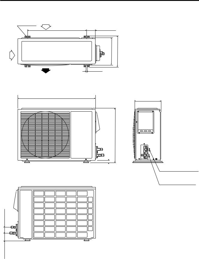
3. DIMENSIONAL DATA
(2)Outdoor Unit: C1852, CL1852
Air intake
4-ø15/32"
23-15/16" 5-11/32"
12-7/32" |
13-5/32" |
15/32"
Air discharge
34-21/32"
21-19/32"
5/8"
2-5/32"
3-7/16"
12-19/32"
Narrow tube service valve ø1/4 (6.35)
Wide tube service valve ø5/8 (15.88)
Unit: inch (mm)
1880_C_I
SM830079
– 13 –
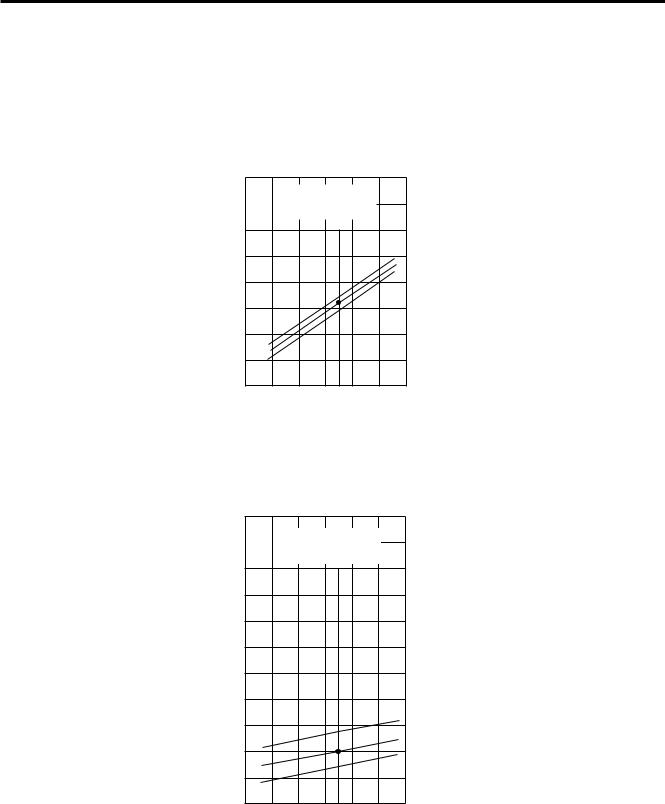
4. PERFORMANCE CHARTS
(1)Operating Current
1 Indoor Unit: XS1852 Outdoor Unit: C1852, CL1852
Operating current characteristics versus outdoor ambient temperature and indoor temperature. (Indoor relative humidity: 50%, Indoor fan speed: High)
230V
|
|
Indoor inlet air |
12 |
|
D.B. temp. °F (°C) |
|
||
|
|
|
(A) |
11 |
|
|
|
|
|
|
10 |
|
|
|
|
|
95 (35.0) |
|
current |
|
|
|
|
|
||
|
|
|
|
|
|
80 (26.7) |
|
9 |
|
|
|
|
|
67 (19.4) |
|
|
|
|
|
|
|
|
|
Operating |
8 |
|
|
|
|
|
|
7 |
|
|
|
|
|
|
|
6 |
|
|
|
|
|
|
|
|
|
|
|
|
|
|
|
|
5 |
70 |
80 |
90 |
100 |
110 |
120 |
|
60 |
||||||
|
(15.6) (21.1) (26.7) (32.2) (37.8) (43.3) (48.9) |
||||||
Outdoor inlet air D.B. temp. °F (°C)
1881_M_I
230V / 208V
150 (10.5) |
|
Indoor inlet air |
|
||
|
|
D.B. temp. °F (°C) |
|
|
140 |
(9.8) |
|
|
|
|
|
|
G) |
|
130 |
(9.1) |
|
|
|
|
|
|
service valve |
|
|
|
|
|
|
|
|
|
2 |
120 |
(8.4) |
|
|
|
|
|
|
|
psig (kg/cm |
|
|
|
|
|
|
|||
110 |
(7.7) |
|
|
|
|
|
|
||
100 |
(7.0) |
|
|
|
|
|
|
||
pressure |
wide tube |
90 |
(6.3) |
|
|
|
|
|
|
80 |
(5.6) |
|
|
|
|
|
95 (35.0) |
||
Low |
at |
|
|
|
|
|
|
|
80 (26.7) |
70 |
(4.9) |
|
|
|
|
|
67 (19.4) |
||
|
|
|
|
|
|
|
|||
|
|
60 |
(4.2) |
|
|
|
|
|
|
|
|
50 |
(3.5) |
70 |
80 |
90 |
100 |
110 |
120 |
|
|
|
60 |
||||||
|
|
|
(15.6) (21.1) |
(26.7) (32.2) |
(37.8) (43.3) (48.9) |
||||
Outdoor inlet air D.B. temp. °F (°C)
1882_M_I
SM830079
– 14 –
 Loading...