


Sanyo VCC-MD600P, VCC-MD400P, VCC-MD800P, VCC-MD700, VCC-MD500 User Manual
...Technical Manual (V(Ver1.04)03)
Color Camera Module
Model No. • NTSC Model
VCC-MD800 (×36, Day/Night type) VCC-MD700 (×36, Color type) VCC-MD600 (×30, Day/Night type) VCC-MD500 (×30, Color type) VCC-MD400 (×22, Day/Night type) VCC-MD300 (×22, Color type)
• PAL Model
VCC-MD800P (×36, Day/Night type) VCC-MD700P (×36, Color type) VCC-MD600P (×30, Day/Night type) VCC-MD500P (×30, Color type) VCC-MD400P (×22, Day/Night type) VCC-MD300P (×22, Color type)
VCC-MD500/MD500P |
VCC-MD400/MD400P |
VCC-MD600/MD600P |
VCC-MD300/MD300P |
VCC-MD700/MD700P |
|
VCC-MD800/MD800P |
|
Please note that specifications and unit exterior design are subject to change without notifications.

Contents
Parts Names and Dimensions......... |
2 |
Connection....................................... |
4 |
[1] Connection of the Interface Board and |
|
Camera Unit........................................................... |
4 |
[2] Interface Board Specifications............................... |
4 |
Input-Output Terminal |
|
Descriptions..................................... |
5 |
[1] Input-Output Terminal Layout and |
|
Specifications......................................................... |
5 |
[2] FFC Compliance.................................................... |
5 |
[3] External Synchronous Signals............................... |
5 |
[4] External Camera Control....................................... |
5 |
Communications Protocol.............. |
6 |
[1] Communications Format........................................ |
6 |
◦Packet Format.................................................... |
6 |
◦Header Format................................................... |
6 |
◦Terminator Format.............................................. |
6 |
◦Message Format................................................ |
6 |
◦Checksum Format.............................................. |
6 |
◦Response Command Format............................. |
6 |
[2] Communications Flow............................................ |
7 |
1 During Settings Command................................ |
7 |
2 During Query Command (Other than ACK)....... |
7 |
3 During Query Command (ACK)......................... |
7 |
[3] Command List for MD800-500............................... |
8 |
[4] Command List (Query) for MD800-500................ |
12 |
[5] Command List for MD400 and 300...................... |
15 |
[6] Command List (Query) for MD400 and 300......... |
19 |
[7] Notes.................................................................... |
20 |
Function Descriptions................... |
27 |
[1] Zoom Control....................................................... |
27 |
[2] Focus Control....................................................... |
28 |
[3] White Balance Control......................................... |
28 |
[4] IRIS Control......................................................... |
29 |
[5] Shutter Speed Control......................................... |
29 |
[6] AGC Control......................................................... |
29 |
[7] Backlight Compensation...................................... |
30 |
[8] Aperture............................................................... |
31 |
[9] Motion Detection.................................................. |
31 |
[10] Day/Night Switch Control................................... |
31 |
[11] Privacy Mask Settings........................................ |
32 |
[12] Stabilizer............................................................ |
34 |
[13] Auto Pursuit Function......................................... |
35 |
Application Software..................... |
36 |
[1] Camera Control Command Transmission............ |
36 |
[2] Communications Error......................................... |
36 |
[3] RS-232C Port....................................................... |
36 |
[4] BAUDRATE......................................................... |
36 |
[5] ID SET, ID Keyboard........................................... |
36 |
Spectral Sensitivity |
|
Characteristics............................... |
37 |
Specifications................................. |
38 |
Change history............................... |
40 |
− 1 −

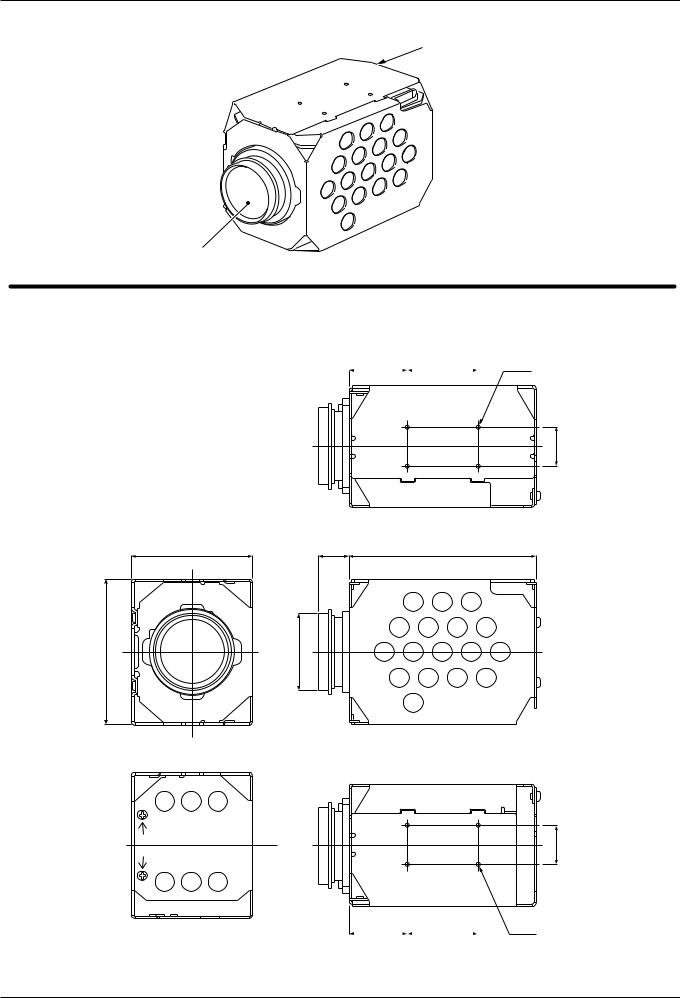
Parts Names and Dimensions
■ VCC-MD800/700/600/500 Series
 CN204 terminal
Lens
■Dimensions
Note: The numbers within the brackets refer to the dimensions of the VCC-MD700 and MD800 models.
|
3-M2 SCREW |
25.1 |
29 |
4-M2 SCREW TAP |
|
TAP |
|
|
|
|
8 |
|
|
|
|
|
|
|
16 |
|
12 |
|
|
|
|
7.1 |
18 |
|
|
|
(2.2) |
|
|
|
50 |
3.53 |
|
84 |
|
60 |
38.6)* |
40.5 |
|
( |
|
3-M2 SCREW |
7.1 |
18 |
4-M2 SCREW TAP |
TAP |
|
||
|
|
|
12 8

 16
16
25.1 29
− 2 −
Parts Names and Dimensions
■ VCC-MD400/MD300 Series
CN204 terminal: MD300
CN301 terminal: MD400
Lens
■Dimensions
Note: The numbers within the brackets refer to the dimensions of the VCC-MD400 model.
24 |
|
29 |
|
4-M2 |
|
|
|
|
|
16
50 |
12.5 |
77 |
60 |
29.7)* |
32.1 |
|
|
|
16
24 |
|
29 |
|
4-M2 |
− 3 −
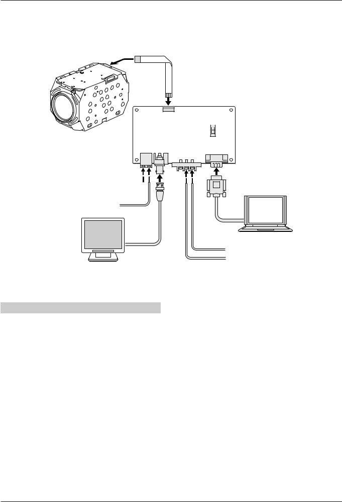
Connection
[1] Connection of the Interface Board and Camera Unit
Connect the camera unit and the interface board using the FFC (flexible flat cable). Connect the various terminals of the interface board using the necessary cables.
FFC
CN005
S0001
B 
A
CN004 |
CN003 |
CN001 |
|
|
CN002 |
GND
V PULSE
DC12V
GND
[2] Interface Board Specifications
Connector |
Terminal Name |
Details |
|
|
|
CN001 |
RS232C |
PC |
CN002 |
Screw |
Power Source |
|
|
(DC12V±1V) |
CN003 |
BNC |
VIDEO OUTPUT |
CN004 |
Push Lock |
V PULSE |
|
|
(External Tuning) |
CN005 |
FC Connector |
Camera Unit Connection |
S0001 |
Slide Switch |
RS-232C Cable Type |
|
|
Selection |
|
|
A Side: Straight Cable |
|
|
B Side: Cross (Interlink) |
|
|
Cable |
■ V PULSE
Input the signal of the following external tuning into the V PULSE terminal (CN004).
Input a signal that satisfies the requirements in
[3] External Synchronous Signals 1 External
Synchronization Specifications on the following page.
− 4 −

Input-Output Terminal Descriptions
[1] Input-Output Terminal Layout and Specifications
Power Supply: DC 6-12V
|
|
|
|
CAMERA |
|
Pin Number |
Signal Name |
Function I/O |
Signal Specifications |
|
|
|
|
|
1 |
RD: RS-232C |
Communication Line |
Low: Max 0.8V |
|
|
|
|
|
|
|
||||
|
|
1 |
RD |
|
|
|
(Receiving) |
High: Min 2.0V |
|
|
|
|
|
|
|
|
|||
|
|
|
|
|
|
2 |
SD: RS-232C |
Communication Line |
Low: Max 0.1V |
|
|
2 |
SD |
||||||
|
|
|
|
|
(Transmitting) |
High: Min 4.4V |
|||
|
|
|
|
|
|||||
|
|
|
|
|
|
|
|
|
|
|
|
3 |
GND |
|
3 |
RD&SD GND |
Communication GND |
— |
|
|
|
||||||||
|
|
|
|
|
|
4 |
DC IN |
DC Power Supply Input |
DC +6 – 12V |
|
|
4 |
DC N (+6 – 12V) |
|
|||||
|
|
|
|
|
|
|
|||
FFC |
|
|
|
|
|
5 |
DC IN GND |
Power Supply GND |
— |
|
5 |
GND (DC) |
|||||||
|
|
6 |
VIDEO OUT |
75Ω C Cut Output |
1.0V±0.2Vp-p |
||||
|
|
|
|
|
|
||||
|
|
6 |
VIDEO |
||||||
|
|
|
|
|
|
|
|||
|
|
|
7 |
VIDEO OUT GND |
Imaging GND |
— |
|||
|
|
|
|||||||
|
|
|
|
|
|
||||
|
|
7 |
GND (VIDEO) |
|
|
|
|
|
|
|
|
|
8 |
LINE IN |
External Tuning Input |
60 (50: PAL) Hz ±0.25 |
|||
|
|
||||||||
|
|
|
|
|
|
|
|
|
Negative Synchronization |
|
|
8 |
LINE IN |
|
|
|
|
||
|
|
|
|
|
|
|
|||
|
|
|
9 |
LINE IN GND |
External |
— |
|||
|
|
|
|
|
|
||||
|
|
9 |
GND (LINE IN) |
||||||
|
|
|
|
|
Synchronization GND |
|
|||
|
|
|
|
|
|
||||
|
|
|
|
|
|
|
|
|
|
[2] FFC Compliance
FCI SFW9R-1STE1LF (Lead Free Product)
Core Number |
9 pin |
Pitch Between Conductors |
1.00±0.05 mm |
Length of Recommended Insulation |
Under 108.0±0.10 mm |
|
|
Thickness of Terminal |
0.30±0.05 mm |
|
|
[3] External Synchronous Signals
This camera module uses external synchronization to synchronize with the camera.
1 External Synchronization Specifications
NTSC Format: 60 Hz±0.25 (Negative
Synchronization)
PAL Format: 50 Hz±0.25 (Negative
Synchronization)
Input the LINE IN signal into the external synchronization signal input terminal of the camera (8 and 9 pins).
Pulse Width: 2m-10 ms
LINE IN
Shaking: |
|
5V |
Less than 50µs |
|
(high: min. 4.0V) |
60 Hz±0.25 Hz |
|
0V |
|
||
|
(low: max. 0.8V) |
|
|
|
Note: Do not input signals other than LINE IN. Image synchronization failure may occur (shaking, jittering, etc.).
2 Internal/External Synchronization
When the power to the camera is turned on, the external signal is input into the external
synchronization signal input terminal (8 and 9 pins). The camera is driven by external synchronization in the case of external synchronization (L-L). Even if external synchronization is input, this does not switch in the case of internal synchronization (INT). When there is no input signal, the 8 pin is set to
Open and High:5V and is automatically set to internal synchronization camera drive.
Note: When the camera is configured to external synchronization (L-L), do not use the 8 pin to fix the LowGND. This shifts the internal synchronization frequency of the camera and normal imaging signals cannot be emitted. Although synchronous switching is automatic even when switching the signal input after
turning the power on, image shaking, etc. may occur.
[4] External Camera Control
This camera module can control the various functions from the RS232C port of a PC, etc.
RS232C Communications Circuit
The communication interface of the camera (1, 2, and 3 pins) is on the C-MOS level. A level shift circuit (5Vp-p 12Vp-p) is separately required to directly input to a PC, etc.
− 5 −

Communications Protocol
[1] Communications Format
The communication unit is a 4 (min)-24 (max) byte packet.
Communications Speed:
2400, 4800, 9600, 19200, 38400 9600 bps
(DEFAULT MD800 – 500)
*MD400 and MD300 cannot connect at 38400bps.
|
DEFAULT is 19200bps. |
|
|
|
|
|
|
|
|
||||||
Data Length: |
8 bit |
|
|
|
|
|
|
|
|
|
|||||
Start Bit: |
1 bit |
|
|
|
|
|
|
|
|
|
|||||
Stop Bit: |
1 bit |
|
|
|
|
|
|
|
|
|
|||||
Parity:None |
|
|
|
|
|
|
|
|
|
|
|
||||
Flow Control: None |
|
|
|
|
|
|
|
|
|
||||||
Packet Format |
|
|
|
|
|
|
|
|
|
||||||
|
|
|
|
|
|
|
|
|
|
|
|
|
|
|
|
|
Header |
Message |
Message |
Message |
|
… |
Checksum |
Terminator |
|||||||
|
|
|
0 |
|
1 |
|
|
2 |
|
|
|
|
|
(0xFF) |
|
|
|
|
|
|
|
|
|
|
|
|
|
|
|
|
|
Header Format |
|
|
|
|
|
|
|
|
|
||||||
|
|
|
|
|
|
|
|
|
|
|
|
|
|
||
|
1 |
|
0/1 |
|
0/1 |
|
0 |
|
0 |
0 |
|
0 |
|
0 |
|
|
|
|
|
|
|
|
|
|
|
|
|
|
|
||
|
Bit 7 |
Bit 6 |
Bit 5 Bit 4 |
|
Bit 3 |
Bit 2 |
|
Bit 1 |
|
Bit 0 |
|||||
|
(MSB) |
|
|
|
|
|
|
|
|
|
|
|
|
(LSB) |
|
Bit 0-2: Fixed [0] *Reserved bit: Camera address (0-7)
Bit 3: Fixed [0] *Reserved bit: During broadcast transmissions
Bit 4: Fixed [0]
Bit 5: During query commands [0], during settings command [1]
Bit 6: During settings/query [0], during response to query [1]
Terminator Format
|
1 |
1 |
1 |
1 |
1 |
1 |
1 |
1 |
|
|
|
|
|
|
|
|
|
|
Bit 7 |
Bit 6 |
Bit 5 |
Bit 4 |
Bit 3 |
Bit 2 |
Bit 1 |
Bit 0 |
|
(MSB) |
|
|
|
|
|
|
(LSB) |
Bit 0-7: Fixed [1] |
|
|
|
|
|
|||
Message Format |
|
|
|
|
|
|||
|
|
|
|
|
|
|
|
|
|
0 |
0/1 |
0/1 |
0/1 |
0/1 |
0/1 |
0/1 |
0/1 |
|
|
|
|
|
|
|
|
|
|
Bit 7 |
Bit 6 |
Bit 5 |
Bit 4 |
Bit 3 |
Bit 2 |
Bit 1 |
Bit 0 |
|
(MSB) |
|
|
|
|
|
|
(LSB) |
Bit 0-6:Refer to the various commands (0-127)
Bit 7: Fixed [0]
Checksum Format
0 |
0/1 |
0/1 |
0/1 |
0/1 |
0/1 |
0/1 |
0/1 |
|
|
|
|
|
|
|
|
Bit 7 |
Bit 6 |
Bit 5 |
Bit 4 |
Bit 3 |
Bit 2 |
Bit 1 |
Bit 0 |
(MSB) |
|
|
|
|
|
|
(LSB) |
Bit 0-6: Take the value that sets the lower 7 bits of the values added from the header to the checksum to 0.
Bit 7: Fixed [0]
Response Command Format
1 |
1 |
1 |
1 |
0/1 |
0/1 |
0/1 |
0/1 |
|
|
|
|
|
|
|
|
Bit 7 |
Bit 6 |
Bit 5 |
Bit 4 |
Bit 3 |
Bit 2 |
Bit 1 |
Bit 0 |
(MSB) |
|
|
|
|
|
|
(LSB) |
Bit 0-3: ACK(Ah) / NACK(Bh) / ERR(Ch)Bit 4-7: Fixed [1]
ACK: This is the response when the process of the received command is correctly completed after receiving the data in the correct format.
NACK: This is the response when data is received in an incorrect format.
ERR: Although the data is received in the correct format, this is the response when the process regarding the received command is incorrect or cannot be conducted.
− 6 −
Communications Protocol
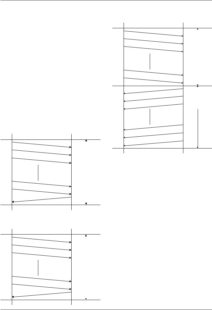
[2] Communications Flow
Note: ◦Start the transmission of the next data after confirming the response command.
◦The maximum transmission interval of the various byte data is 500 [msec]. If this is exceeded, a communication error is detected in the camera unit, the receiving data is deleted, and data from the header is waiting to be received again. Furthermore, there are no special regulations regarding the minimum value.
◦All the commands can be acquired after the periods below after start-up.
MD600(P), MD500(P): 6 seconds MD800(P), MD700(P): 9 seconds
When auto pixel defect compensation is set to ON, below period will be added to above at the longest.
MD600(P), MD500(P): 15seconds MD800(P), MD700(P): 20seconds In factory default, Auto pixel defect
compensation is set to OFF at start-up.
1 During Settings Command
Transmission |
Transmission |
||
Source |
Destination (Unit) |
||
|
Header |
|
|
|
|
|
|
|
Message 1 |
|
|
|
Message 2 |
|
|
|
Repeats the byte |
|
|
|
|
|
|
|
count and the message |
Settings Command |
|
|
and response commu- |
Transmissions |
|
|
nications in response |
|
|
|
to the contents of the |
|
|
|
message. |
|
|
|
Checksum |
|
|
|
Terminator |
|
|
Response Command |
|
|
|
|
|
|
|
2 During Query Command (Other than ACK)
Transmission |
Transmission |
||
Source |
Destination (Unit) |
||
|
Header |
|
|
|
|
|
|
|
Message 1 |
|
|
|
Message 2 |
|
|
|
Repeats the byte |
|
|
|
Query Command |
||
|
count and the message |
||
|
Transmissions |
||
|
and response commu- |
|
|
|
nications in response |
|
|
|
to the contents of the |
|
|
|
message. |
|
|
|
Checksum |
|
|
|
Terminator |
|
|
Response Command |
|
|
|
(NACK/ERR) |
|
|
|
|
|
|
|
3 During Query Command (ACK)
Transmission |
Transmission |
||
Source |
Destination (Unit) |
||
|
Header |
|
|
|
|
|
|
|
Message 1 |
|
|
|
Message 2 |
|
|
|
Repeats the byte |
|
|
|
Query Command |
||
|
count and the message |
||
|
and response commu- |
Transmissions |
|
|
nications in response |
|
|
|
to the contents of the |
|
|
|
message. |
|
|
|
Checksum |
|
|
|
Terminator |
|
|
Header |
|
|
|
|
|
|
|
|
|
|
|
Message 1 |
|
|
|
Message 2 |
|
Query Command |
|
|
Response |
||
Repeats the byte count and the message and response communications in response to the contents of the message.
Checksum
Terminator
Response Command (ACK)
− 7 −
Communications Protocol |
|
|
|
|
Model: VCC-MD800/700/600/500 |
||||||||
[3] Command List for MD800-500 |
|
|
|
|
|
||||||||
|
|
|
|
|
|
|
|
|
|
|
|
|
|
Message |
|
|
|
|
|
|
|
|
|
|
|
|
|
System |
|
All Initial |
A0 |
01 |
0A |
CS |
FF |
|
|
|
|
Initialization of Unadjusted EEPROM Values (Set to Factory Defaults) |
|
|
|
All Menu Initial |
A0 |
01 |
0B |
CS |
FF |
|
|
|
|
Initialization of All Menu Settings |
|
|
|
Lens Initial |
A0 |
01 |
0C |
CS |
FF |
|
|
|
|
Detection of initial lens position |
|
|
|
Reset |
A0 |
01 |
0D |
CS |
FF |
|
|
|
|
Restarting camera (Saves the setting value) |
|
|
|
Menu Initial |
A0 |
01 |
0E |
CS |
FF |
|
|
|
|
Initialization of menu settings other than privacy mask settings |
|
|
|
Pixel defect compensation |
A0 |
01 |
12 |
00 |
06 |
04 |
04 |
06 |
00 |
Applied version 1.21-** or later |
(Note 8) |
|
|
|
|
0C |
CS |
FF |
|
|
|
|
|
|
|
|
|
Auto pixel defect |
A0 |
01 |
13 |
0p |
CS |
FF |
|
|
|
p: 0:OFF Default , 1:ON |
|
|
|
compensation at start-up. |
|
|
|
|
|
|
|
|
|
Applied version 1.21-** or later |
|
|
|
|
|
|
|
|
|
|
|
|
|
Refer to "Communications Protocol [2]Communications Flow" |
|
Zoom |
|
Tele |
A0 |
02 |
05 |
CS |
FF |
|
|
|
|
|
|
|
|
Wide |
A0 |
02 |
06 |
CS |
FF |
|
|
|
|
|
|
|
|
Tele/Wide Stop |
A0 |
02 |
07 |
CS |
FF |
|
|
|
|
|
|
|
|
Tele/Wide Speed |
A0 |
02 |
08 |
0p |
CS |
FF |
|
|
|
p: Speed 1-4 during Tele and Wide commands (1: Slow-4: Fast [Initial value: 3]) |
|
|
|
|
|
|
|
|
|
|
|
|
|
|
|
|
|
Direct |
A0 |
02 |
09 |
0p |
0q |
0r |
CS |
FF |
|
pqr: Direct Position |
|
|
|
|
|
|
|
|
|
|
|
|
|
MD800/700, 0: Wide, 2484: 36x (optical), 2724: 576x (digital) |
|
|
|
|
|
|
|
|
|
|
|
|
|
MD600/500, 0: Wide, 2263: 30x (optical), 2503: 480x (digital) |
|
|
|
|
|
|
|
|
|
|
|
|
|
Digital Zoom Tele Limiter command needs to be sent before moving to digital zoom field. |
|
|
|
Zoom Direct with Focus |
A0 |
02 |
0A |
0p |
0q |
0r |
0s |
0t |
0u |
pqr:Zoom Direct Position stu:Focus Direct Position |
|
|
|
|
|
CS |
FF |
|
|
|
|
|
|
For carrying set the focus to the specified position. |
|
|
|
Digital Zoom Tele Limiter |
A0 |
02 |
18 |
0p |
CS |
FF |
|
|
|
p: Maximum digital zoom magnification (0: x0 [Initial value], 1: x2, 2: x4, 3: x8, 4: x16) |
|
|
|
Optical Zoom Wide/Tele |
A0 |
02 |
19 |
xx |
yy |
CS |
FF |
|
|
Wide/Tele Optical ZOOM Limiter The numbers within the brackets refer to the MD600/500 models |
|
|
|
Limitter |
|
|
|
|
|
|
|
|
|
xx: 0, 1-35 [29] (0 is no limit and 1-35 [29] is the Wide optical ZOOM limit) |
|
|
|
|
|
|
|
|
|
|
|
|
|
yy: 0, 2-36 [30] (0 is no limit and 2-36 [30] is the Tele optical ZOOM limit) |
|
|
|
|
|
|
|
|
|
|
|
|
|
Note: Ensure that xx < yy |
|
|
|
V-Reso.UP OFF/ON |
A0 |
02 |
1F |
0p |
CS |
FF |
|
|
|
p: Increased vertical sensitivity settings during digital zoom OFF/ON (0: OFF, 1: ON) |
(Note 3) |
|
|
Zoom Preset ON |
A0 |
02 |
28 |
CS |
FF |
|
|
|
|
Moves the zoom position to the optical TELE edge |
|
|
|
Zoom Preset OFF |
A0 |
02 |
29 |
CS |
FF |
|
|
|
|
Returns the zoom position to the position before the “Zoom Preset ON” operation |
|
Focus |
|
Auto Focus ON |
A0 |
03 |
00 |
CS |
FF |
|
|
|
|
|
|
|
|
Manual Focus ON |
A0 |
03 |
01 |
CS |
FF |
|
|
|
|
|
|
|
|
One Push Trigger |
A0 |
03 |
03 |
CS |
FF |
|
|
|
|
Operates the auto focus operation once |
|
|
|
Far |
A0 |
03 |
05 |
CS |
FF |
|
|
|
|
|
|
|
|
Near |
A0 |
03 |
06 |
CS |
FF |
|
|
|
|
|
|
|
|
|
|
|
|
|
|
|
|
|
|
|
|
|
|
Far/Near Stop |
A0 |
03 |
07 |
CS |
FF |
|
|
|
|
|
|
|
|
Far/Near Speed |
A0 |
03 |
08 |
0p |
CS |
FF |
|
|
|
p: Speed 1-4 during Far and Near commands (1: Slow-4: Fast (Initial value: 2)) |
|
|
|
Direct |
A0 |
03 |
09 |
0p |
0q |
0r |
CS |
FF |
|
pqr: Direct Position (0: Far 1209: Near) |
|
|
|
Near Limiter |
A0 |
03 |
0E |
0p |
CS |
FF |
|
|
|
p: Subject distance limit during auto focus and manual focus |
|
|
|
|
|
|
|
|
|
|
|
|
|
(0: 10 cm, 1: 30cm, 2: 50 cm, 3: 1 m [Initial value], 4: 3 m, 5: 5 m) |
|
|
|
Auto Focus Sensitivity |
A0 |
03 |
10 |
0p |
CS |
FF |
|
|
|
p: Auto focus restart sensitivity settings (0: LOW/1: HI [Initial value]) |
|
|
|
Focus Area |
A0 |
03 |
13 |
0p |
CS |
FF |
|
|
|
Settings Determining Auto Focus Areas 1-3 |
|
|
|
|
|
|
|
|
|
|
|
|
|
1: Entire screen-3: Only center of the screen (Initial value: 2) |
|
|
|
Cover Offset OFF/ON |
A0 |
03 |
15 |
0p |
CS |
FF |
|
|
|
p: Offset OFF/ON (0: OFF/1: ON) when using the cover |
|
|
|
Cover Offset Level |
A0 |
03 |
16 |
0p |
0q |
CS |
FF |
|
|
pq: Offset Level Setting 0 – 00 (Initial value: 5) when using the cover |
|
|
|
Auto Focus Mode during pan/tilt |
A0 |
03 |
1F |
0p |
CS |
FF |
|
|
|
p: Auto Focus Mode Setting during Pan/Tilt (0: AF/1: Fixed) |
|
White |
|
ATW |
A0 |
04 |
00 |
CS |
FF |
|
|
|
|
Auto White Balance Mode (Same as "0" in WB Mode) |
|
Balance |
|
MWB |
A0 |
04 |
01 |
CS |
FF |
|
|
|
|
Manual White Balance Mode (Same as "2" in WB Mode) |
|
|
|
One Push Trigger (AWC Set) |
A0 |
04 |
03 |
CS |
FF |
|
|
|
|
Executes OnePush in AWC Mode |
|
|
|
AWC Reset |
A0 |
04 |
04 |
CS |
FF |
|
|
|
|
Returns to the original mode only after executing the OnePush Trigger command |
|
|
|
ATW Smart OFF/ON |
A0 |
04 |
06 |
0p |
CS |
FF |
|
|
|
Smart ATW (high color saturation compensation) ON/OFF (OFF: 0 [Initial value], ON: 1) |
|
|
|
|
|
|
|
|
|
|
|
|
|
*This mode is valid when WB mode is set to ATW. |
|
|
|
|
|
|
|
|
|
|
|
|
|
|
|
|
|
WB Mode |
A0 |
04 |
07 |
0p |
CS |
FF |
|
|
|
p: White Balance Mode 0-5 |
|
|
|
|
|
|
|
|
|
|
|
|
|
0: Auto White Balance, 1: AWC Mode (One-Push N/A), 2: Manual White Balance |
|
|
|
|
|
|
|
|
|
|
|
|
|
3: 3200K Fixed Mode, 4: 5600K Fixed Mode, 5: FLUO Mode (4200K Fixed) |
|
|
|
MWB Red + |
A0 |
04 |
0B |
CS |
FF |
|
|
|
|
|
|
|
|
MWB Red - |
A0 |
04 |
0C |
CS |
FF |
|
|
|
|
|
|
|
|
MWB Red Preset |
A0 |
04 |
0F |
CS |
FF |
|
|
|
|
Returns MWB red component settings to factory defaults (Initial value: 64) |
|
|
|
MWB Red Direct |
A0 |
04 |
13 |
0p |
0q |
CS |
FF |
|
|
pq: Direct MWB red components 0-255 |
|
|
|
MWB Blue + |
A0 |
04 |
15 |
CS |
FF |
|
|
|
|
|
|
|
|
MWB Blue - |
A0 |
04 |
16 |
CS |
FF |
|
|
|
|
|
|
|
|
MWB Blue Preset |
A0 |
04 |
19 |
CS |
FF |
|
|
|
|
Returns MWB blue component settings to factory defaults (Initial value: 64) |
|
|
|
MWB Blue Direct |
A0 |
04 |
1D |
0p |
0q |
CS |
FF |
|
|
pq: Direct MWB blue components 0-255 |
|
|
|
ATW Masking OFF |
A0 |
04 |
28 |
CS |
FF |
|
|
|
|
Mask settings ON/OFF during ATW |
|
|
|
ATW Masking ON |
A0 |
04 |
29 |
CS |
FF |
|
|
|
|
|
|
|
|
ATW Mask Area Clr |
A0 |
04 |
2D |
CS |
FF |
|
|
|
|
Initialization of mask settings during ATW |
|
|
|
ATW Mask Area Set |
A0 |
04 |
31 |
0p |
0q |
0r |
0s |
0t |
0u |
Mask area settings during ATW |
(Note 1) |
|
|
|
|
0v |
0w |
0x |
0y |
0z |
0n |
CS |
FF |
|
|
|
|
ATW Mask Display |
A0 |
04 |
32 |
0p |
CS |
FF |
|
|
|
p: Displays the ATW MASK settings status on the monitor. (1: ON/0: OFF) |
|
Iris |
|
Auto IRIS |
A0 |
05 |
00 |
CS |
FF |
|
|
|
|
|
(Note 3) |
|
|
Manual IRIS (EI OFF) |
A0 |
05 |
01 |
CS |
FF |
|
|
|
|
|
|
|
|
Manual IRIS (EI ON) |
A0 |
05 |
02 |
CS |
FF |
|
|
|
|
|
(Note 3) |
|
|
Iris Level + |
A0 |
05 |
0B |
CS |
FF |
|
|
|
|
Iris level operation during auto iris |
|
|
|
Iris Level - |
A0 |
05 |
0C |
CS |
FF |
|
|
|
|
|
|
|
|
|
|
|
|
|
|
||||||
|
|
Iris Level Preset |
A0 |
05 |
0F |
CS |
FF |
|
|
|
|
Returns iris levels during auto iris to factory defaults (Initial value: 40) |
|
|
|
Iris Level Direct |
A0 |
05 |
13 |
0p |
0q |
CS |
FF |
|
|
pq: Iris level 0 (Dark) - 100 (Bright) during auto iris (Initial value: 40) |
|
|
|
Manual Iris Stop + |
A0 |
05 |
15 |
CS |
FF |
|
|
|
|
Aperture operation during manual iris (Initial value: 17) |
|
|
|
Manual Iris Stop - |
A0 |
05 |
16 |
CS |
FF |
|
|
|
|
|
|
|
|
|
|
|
|
|
|
||||||
|
|
Manual Iris Stop Preset |
A0 |
05 |
19 |
CS |
FF |
|
|
|
|
Returns aperture during manual iris to factory default (Initial value: 17) |
|
|
|
Manual Iris Stop Direct |
A0 |
05 |
1D |
p |
CS |
FF |
|
|
|
p: Aperture 1 (Close) - 17 (Open) during manual iris |
|
|
CS: Checksum |
|
|
|
|
|
|
|
|
|
|
|
|
|
FF: Terminator |
|
|
|
|
|
|
|
|
|
|
|
|
− 8 −

Communications Protocol |
|
|
|
|
Model: VCC-MD800/700/600/500 |
||||||||
|
|
|
|
|
|
|
|
|
|
|
|
|
|
Message |
|
|
|
|
|
|
|
|
|
|
|
|
|
Backlight |
|
BLC OFF |
A0 |
06 |
00 |
CS |
FF |
|
|
|
|
Backlight compensation OFF |
|
|
|
Multi BLC ON |
A0 |
06 |
01 |
CS |
FF |
|
|
|
|
Backlight compensation multifractionated evaluative metering mode (Backlight compensates after |
|
|
|
|
|
|
|
|
|
|
|
|
|
measuring the light of the entire screen.) |
|
|
|
Multi BLC Weight - |
A0 |
06 |
04 |
00 |
CS |
FF |
|
|
|
Sensitivity settings during Multi BLC |
|
|
|
Multi BLC Weight + |
A0 |
06 |
04 |
01 |
CS |
FF |
|
|
|
BLC is easier to determine with a larger value (Initial value: 7) |
|
|
|
|
|
|
|
|
|||||||
|
|
Multi BLC Weight Preset |
A0 |
06 |
05 |
CS |
FF |
|
|
|
|
Returns sensitivity during Multi BLC to factory defaults (Initial value: 7) |
|
|
|
Multi BLC Weight Direct |
A0 |
06 |
06 |
0p |
CS |
FF |
|
|
|
p: Direct sensitivity settings 0-15 during Multi BLC (Initial value: 7) |
|
|
|
Multi BLC Bright - |
A0 |
06 |
07 |
00 |
CS |
FF |
|
|
|
Brightness settings during Multi BLC |
|
|
|
|
|
|
|
|
|
|
|
|
|
Larger value increases brightness when determining BLC (Initial value: 7) |
|
|
|
Multi BLC Bright + |
A0 |
06 |
07 |
01 |
CS |
FF |
|
|
|
|
|
|
|
|
|
|
|
|
|||||||
|
|
Multi BLC Bright Preset |
A0 |
06 |
08 |
CS |
FF |
|
|
|
|
Returns brightness settings during Multi BLC to factory defaults (Initial value: 7) |
|
|
|
Multi BLC Bright Direct |
A0 |
06 |
09 |
0p |
CS |
FF |
|
|
|
p: Direct brightness settings 0-15 during Multi BLC (Initial value: 7) |
|
|
|
Center BLC ON |
A0 |
06 |
0B |
CS |
FF |
|
|
|
|
BLC center-weighted metering mode (Backlight compensates after measuring the light mainly in the |
|
|
|
|
|
|
|
|
|
|
|
|
|
center.) |
|
|
|
Center BLC Weight Preset |
A0 |
06 |
0F |
CS |
FF |
|
|
|
|
Returns sensitivity settings during Center BLC to factory defaults (Each initial value: 0) |
|
|
|
|
|
|
|
|
|
|
|
|
|
* Therefore, Center is always 7 |
|
|
|
Center BLC Weight Direct |
A0 |
06 |
10 |
0p |
0q |
0r |
0s |
CS |
FF |
Sensitivity settings during Center BLC |
|
|
|
|
|
|
|
|
|
|
|
|
|
p: Top(0-7) q: Bottom(0-7) r: Left(0-7) s: Right(0-7) (Each initial value: 0) |
|
|
|
Center BLC Area Preset |
A0 |
06 |
12 |
CS |
FF |
|
|
|
|
Returns center area settings during Center BLC to factory defaults (Each initial value: 0) |
|
|
|
Center BLC Area Direct |
A0 |
06 |
13 |
0p |
0q |
0r |
0s |
CS |
FF |
Center area settings during Center BLC |
|
|
|
|
|
|
|
|
|
|
|
|
|
p: x-position(0-7) q: y-position(0-5) r: x-size(0-7) s: y-size(0-5) |
|
|
|
|
|
|
|
|
|
|
|
|
|
(Initial value: x-position: 2 y-position: 1 x-size: 3 y-size: 3) |
|
|
|
|
|
|
|
|
|
|
|
|
|
*When x-size:0 y-size:0, it becomes 1 area. |
|
|
|
Center BLC Area Display |
A0 |
06 |
14 |
0p |
0q |
CS |
FF |
|
|
Displays the Center BLC Area settings status on the monitor. p: Display (0: OFF, 1: ON), |
|
|
|
|
|
|
|
|
|
|
|
|
|
q: Displayed area (0: CENTER, 1: TOP, 2: BOTTOM, 3: LEFT, 4: RIGHT) |
|
|
|
|
|
|
|
|
|
|
|
|
|
* The area that is not covered with zebra markings shows the setting area. |
|
|
|
Mask BLC ON |
A0 |
06 |
15 |
CS |
FF |
|
|
|
|
BLC mask mode (Backlight compensates after measuring the light, ignoring areas set as mask.) |
|
|
|
Mask BLC Area Preset |
A0 |
06 |
19 |
CS |
FF |
|
|
|
|
Return mask area settings during Mask BLC to factory defaults |
|
|
|
Mask BLC Area Direct |
A0 |
06 |
1D |
0p |
0q |
0r |
0s |
0t |
0u |
Mask area settings during Mask BLC |
(Note 1) |
|
|
|
|
0v |
0w |
0x |
0y |
0z |
0n |
CS |
FF |
|
|
|
|
BLC ON |
A0 |
06 |
33 |
CS |
FF |
|
|
|
|
Returns to the mode before BLC OFF only when BLC OFF |
|
|
|
BLC Mask Display |
A0 |
06 |
1E |
0p |
CS |
FF |
|
|
|
p: Displays the BLC MASK settings status on the monitor. (1: ON/0: OFF) |
|
Shutter |
|
Shutter Speed + |
A0 |
07 |
0B |
CS |
FF |
|
|
|
|
Increases shutter speed by one notch (Long time mode x 32 – High speed mode 1/10000) |
(Note 3) |
Speed |
|
|
|
|
|
|
|
|
|
|
|
|
|
|
Shutter Speed - |
A0 |
07 |
0C |
CS |
FF |
|
|
|
|
Decreases shutter speed by one notch (Long time mode x 32 – High speed mode 1/10000) |
(Note 3) |
|
|
|
|
|
|
|
||||||||
|
|
Shutter Speed Set long |
A0 |
07 |
0E |
0p |
CS |
FF |
|
|
|
Shutter Speed Mode Settings |
(Note 3) |
|
|
|
|
|
|
|
|
|
|
|
|
0: Prolonged exposure shutter mode, 1: Normal mode, 3: High speed shutter mode |
|
|
|
Shutter Speed OFF |
A0 |
07 |
0F |
CS |
FF |
|
|
|
|
Returns the shutter speed mode setting to normal mode setting |
|
|
|
Shutter Long Direct |
A0 |
07 |
11 |
0p |
CS |
FF |
|
|
|
Shutter speed settings during prolonged exposure shutter mode |
|
|
|
|
|
|
|
|
|
|
|
|
|
(0: x1, 1: x2, 2: x4, 3: x8, 4: x16, 5: x32) |
|
|
|
Shutter Short Direct |
A0 |
07 |
12 |
0p |
CS |
FF |
|
|
|
Shutter speed settings during high speed shutter mode |
|
|
|
|
|
|
|
|
|
|
|
|
|
The numbers within the brackets refer to the PAL model |
|
|
|
|
|
|
|
|
|
|
|
|
|
(0: 1/60 [1/50], 1:1/100 [1/120], 2: 1/250, 3: 1/500, 4: 1/1000, 5: 1/2000, 6: 1/4000, 7: 1/10000) |
|
|
|
Sense Up + |
A0 |
07 |
1A |
CS |
FF |
|
|
|
|
Increase electronic sensitivity settings |
(Note 3) |
|
|
Sense Up - |
A0 |
07 |
1B |
CS |
FF |
|
|
|
|
|
|
|
|
Sense Up Direct |
A0 |
07 |
1D |
0p |
CS |
FF |
|
|
|
p: Direct increased electronic sensitivity settings |
(Note 3) |
|
|
|
|
|
|
|
|
|
|
|
|
(0: OFF, 1: x2, 2: x4, 3: x8, 4: x16, 5: x32) |
|
|
|
ELS OFF |
A0 |
07 |
28 |
CS |
FF |
|
|
|
|
Sets shutter speed to 1x (1/60 [1/50]) after saving |
|
|
|
|
|
|
|
|
|
|
|
|
|
The numbers within the brackets refer to the PAL model |
|
|
|
ELS ON |
A0 |
07 |
29 |
CS |
FF |
|
|
|
|
Returns to electronic shutter speed saved by ELS OFF |
|
Motion |
|
Motion Detector OFF |
A0 |
08 |
00 |
CS |
FF |
|
|
|
|
Motion sensor ON/OFF |
(Note 3) |
Detector |
|
Motion Detector ON |
A0 |
08 |
01 |
CS |
FF |
|
|
|
|
||
|
|
|
|
|
|
|
|||||||
|
|
Motion Size Preset |
A0 |
08 |
05 |
CS |
FF |
|
|
|
|
Returns detected motion size settings to factory defaults (Initial value: V-Size: 1, H-Size: 1) |
|
|
|
Motion Size Direct |
A0 |
08 |
06 |
0p |
0q |
CS |
FF |
|
|
Detected motion size settings p: V-Size (1-6) q: H-Size (1-8) VxH MAX 9 (Initial value: V-Size: |
|
|
|
|
|
|
|
|
|
|
|
|
|
1, H-Size: 1) |
|
|
|
Motion Size Display |
A0 |
08 |
07 |
0p |
CS |
FF |
|
|
|
p: Displays the MOTION SIZE settings status on the monitor. (1: ON/0: OFF) |
|
|
|
Masking OFF |
A0 |
08 |
0A |
CS |
FF |
|
|
|
|
Mask area settings for motion detection ON/OFF |
|
|
|
Masking ON |
A0 |
08 |
0B |
CS |
FF |
|
|
|
|
|
|
|
|
|
|
|
|
|
|
||||||
|
|
Mask Area Preset |
A0 |
08 |
0F |
CS |
FF |
|
|
|
|
Returns mask area for motion detection to factory defaults |
|
|
|
Mask Area Direct |
A0 |
08 |
13 |
0p |
0q |
0r |
0s |
0t |
0u |
Mask area settings for motion detection |
(Note 1) |
|
|
|
|
0v |
0w |
0x |
0y |
0z |
0n |
CS |
FF |
|
|
|
|
Motion Mask Display |
A0 |
08 |
14 |
0p |
CS |
FF |
|
|
|
p: Displays the MOTION MASK settings status on the monitor. (1: ON/0: OFF) |
|
|
|
Sensitivity Move + |
A0 |
08 |
15 |
CS |
FF |
|
|
|
|
Motion detection sensitivity settings (Initial value: 5) |
|
|
|
Sensitivity Move - |
A0 |
08 |
16 |
CS |
FF |
|
|
|
|
* Smaller values increase the sensitivity to small movements. |
|
|
|
Sensitivity Move Preset |
A0 |
08 |
19 |
CS |
FF |
|
|
|
|
Returns motion detection sensitivity settings to factory defaults (Initial value: 5) |
|
|
|
Sensitivity Move Direct |
A0 |
08 |
1D |
0p |
CS |
FF |
|
|
|
p: Direct motion detection sensitivity settings 1-10 (Initial value: 5) |
|
|
|
Sensitivity Y-Level + |
A0 |
08 |
1F |
CS |
FF |
|
|
|
|
Minimum brightness settings for motion detection (Initial value: 5) |
|
|
|
Sensitivity Y-Level - |
A0 |
08 |
20 |
CS |
FF |
|
|
|
|
* Smaller values increase the sensitivity to movements even on dark screens. |
|
|
|
Sensitivity Y-Level Peset |
A0 |
08 |
23 |
CS |
FF |
|
|
|
|
Returns minimum brightness settings for motion detection to factory default (Initial value: 5) |
|
|
|
Sensitivity Y-Level Direct |
A0 |
08 |
27 |
0p |
CS |
FF |
|
|
|
p: Direct minimum brightness settings for motion detection 1-10 (Initial value: 5) |
|
|
|
Sensitivity Y-Differ + |
A0 |
08 |
29 |
CS |
FF |
|
|
|
|
Brightness variation settings for undetected motion (Initial value: 5) |
|
|
|
Sensitivity Y-Differ - |
A0 |
08 |
2A |
CS |
FF |
|
|
|
|
* Smaller values increase the sensitivity to movements even with large brightness variation. |
|
|
|
Sensitivity Y-Differ Preset |
A0 |
08 |
2D |
CS |
FF |
|
|
|
|
Returns brightness variation settings for undetected motion to factory defaults (Initial value: 5) |
|
|
|
Sensitivity Y-Differ Direct |
A0 |
08 |
31 |
0p |
CS |
FF |
|
|
|
p: Direct brightness variation settings for undetected motion 1-10 (Initial value: 5) |
|
|
|
Sensitivity Duration + |
A0 |
08 |
33 |
CS |
FF |
|
|
|
|
Continuous movement time for motion detection (Initial value: 1) |
|
|
|
Sensitivity Duration - |
A0 |
08 |
34 |
CS |
FF |
|
|
|
|
* Smaller values increase the sensitivity to fast moving subjects. |
|
|
|
Sensitivity Duration Preset |
A0 |
08 |
37 |
CS |
FF |
|
|
|
|
Returns continuous movement time for motion detection to factory defaults (Initial value: 1) |
|
|
|
Sensitivity Duration Direct |
A0 |
08 |
3B |
p |
CS |
FF |
|
|
|
p: Direct continuous movement time for motion detection 1-60 (Initial value: 1) |
|
|
|
Motion Zoom |
A0 |
08 |
3D |
0p |
CS |
FF |
|
|
|
p: Zoom magnification during motion detection (Initial value: 0) |
|
|
|
|
|
|
|
|
|
|
|
|
|
(0: OFF, 1: x1.4, 2: x2, 3: x2.8, 4: x4, 5: x5.6, 6: x 1/1.4, 7: x 1/2, 8: x 1/2.8, 9: x 1/4, 10: x 1/5.6) |
|
|
|
Motion Interval |
A0 |
08 |
42 |
0p |
CS |
FF |
|
|
|
p: Interval time until the start of next detection during motion detection (Initial value: 0) |
|
|
|
|
|
|
|
|
|
|
|
|
|
(0: 5s, 1: 10s, 2: 15s, 3: 20s, 4: 30s, 5: 1m, 6: 2m, 7: 3m, 8: 4m, 9: 5m) |
|
|
CS: Checksum |
|
|
|
|
|
|
|
|
|
|
|
|
|
FF: Terminator |
|
|
|
|
|
|
|
|
|
|
|
|
− 9 −
Communications Protocol |
|
|
|
|
|
Model: VCC-MD800/700/600/500 |
||||||
|
|
|
|
|
|
|
|
|
|
|
|
|
Message |
|
|
|
|
|
|
|
|
|
|
|
|
Sync |
Sync INT |
A0 |
09 |
00 |
CS |
FF |
|
|
|
|
Internal synchronization mode |
|
|
Sync L-L |
A0 |
09 |
01 |
CS |
FF |
|
|
|
|
Power supply synchronization mode |
|
|
L-L Phase + |
A0 |
09 |
0B |
CS |
FF |
|
|
|
|
Synchronous phase settings for power source synchronization |
|
|
L-L Phase - |
A0 |
09 |
0C |
CS |
FF |
|
|
|
|
||
|
|
|
|
|
|
|
||||||
|
L-L Phase Preset |
A0 |
09 |
0F |
CS |
FF |
|
|
|
|
Returns synchronous phase settings for power source synchronization to factory defaults |
|
|
|
|
|
|
|
|
|
|
|
|
(Initial value: 0) |
|
|
L-L Phase Direct |
A0 |
09 |
13 |
0p |
0q |
0r |
CS |
FF |
|
pqr: Synchronous phase settings for power source synchronization |
|
|
|
|
|
|
|
|
|
|
|
|
Direct 0-524 (NTSC) / 0-624 (PAL) (Initial value: 0) |
|
AGC |
COLOR MAX Gain |
A0 |
0A |
00 |
0p |
CS |
FF |
|
|
|
p: AGC MAX Gain settings during COLOR (0: LOW, 1: NORM, 2: MID, 3: HIGH) |
|
|
B/W MAX Gain |
A0 |
0A |
01 |
0p |
CS |
FF |
|
|
|
p: AGC MAX Gain settings during B/W (0: LOW, 1: NORM, 2: MID, 3: HIGH) |
|
|
AUTO MAX Gain |
A0 |
0A |
02 |
0p |
CS |
FF |
|
|
|
p: AGC MAX Gain settings during AUTO (1: NORM, 2: MID, 3: HIGH) |
|
|
AGC ON/OFF |
A0 |
0A |
03 |
0p |
CS |
FF |
|
|
|
p: AGC ON/OFF switch (Cannot be set to OFF when D/N AUTO or when SENSE UP setting is enabled) |
|
|
|
|
|
|
|
|
|
|
|
|
(0:OFF, 1:ON) |
(Note 3) |
|
COLOR AGC_OFF Gain + |
A0 |
0A |
0B |
CS |
FF |
|
|
|
|
Gain settings when COLOR and AGC are OFF (Initial value: 0dB) |
|
|
COLOR AGC_OFF Gain - |
A0 |
0A |
0C |
CS |
FF |
|
|
|
|
||
|
|
|
|
|
|
|
||||||
|
B/W AGC_OFF Gain + |
A0 |
0A |
0D |
CS |
FF |
|
|
|
|
Gain settings when B/W and AGC are OFF (Initial value: 0dB) |
|
|
B/W AGC_OFF Gain - |
A0 |
0A |
0E |
CS |
FF |
|
|
|
|
||
|
|
|
|
|
|
|
||||||
|
Gain Preset |
A0 |
0A |
0F |
CS |
FF |
|
|
|
|
Returns gain settings when AGC is OFF to factory defaults |
|
|
|
|
|
|
|
|
|
|
|
|
(D/N camera is both COLOR and B/W) (Initial value: 0dB) |
|
|
Gain Direct (COLOR) |
A0 |
0A |
12 |
0p |
CS |
FF |
|
|
|
p: Gain settings when COLOR and AGC are OFF |
|
|
|
|
|
|
|
|
|
|
|
|
(0: 0dB, 1: 3dB, 2: 6dB, 3: 9dB, 4: 12dB, 5: 15dB, 6: 18dB, 7: 21dB, 8: 24dB, 9: 27dB, 10: 30dB) |
|
|
Gain Direct (B/W) |
A0 |
0A |
13 |
0p |
CS |
FF |
|
|
|
p: Gain settings when B/W and AGC are OFF |
|
|
|
|
|
|
|
|
|
|
|
|
(0: 0dB, 1: 3dB, 2: 6dB, 3: 9dB, 4: 12dB, 5: 15dB, 6: 18dB, 7: 21dB, 8: 24dB, 9: 27dB, 10: 30dB) |
|
Aperture |
OFF |
A0 |
0B |
00 |
CS |
FF |
|
|
|
|
|
|
|
|
|
|
|
|
|
|
|
|
|
|
|
|
ON |
A0 |
0B |
01 |
CS |
FF |
|
|
|
|
|
|
|
Aperture V + |
A0 |
0B |
0B |
CS |
FF |
|
|
|
|
Vertical contour compensation settings |
|
|
Aperture V - |
A0 |
0B |
0C |
CS |
FF |
|
|
|
|
||
|
|
|
|
|
|
|
||||||
|
Aperture V Preset |
A0 |
0B |
0F |
CS |
FF |
|
|
|
|
Returns vertical contour compensation settings to factory defaults (Initial value: 8) |
|
|
Aperture V Direct |
A0 |
0B |
13 |
0p |
CS |
FF |
|
|
|
p: Vertical contour compensation settings 1-15 (Initial value: 8) |
|
|
Aperture H + |
A0 |
0B |
15 |
CS |
FF |
|
|
|
|
Horizontal contour compensation settings (Initial value: 8) |
|
|
Aperture H - |
A0 |
0B |
16 |
CS |
FF |
|
|
|
|
||
|
|
|
|
|
|
|
||||||
|
Aperture H Preset |
A0 |
0B |
19 |
CS |
FF |
|
|
|
|
Returns horizontal contour compensation settings to factory defaults (Initial value: 8) |
|
|
Aperture H Direct |
A0 |
0B |
1D |
0p |
CS |
FF |
|
|
|
p: Horizontal contour compensation settings 1-15 (Initial value: 8) |
|
Gamma |
OFF |
A0 |
0C |
00 |
CS |
FF |
|
|
|
|
Gamma OFF (1) |
|
|
ON |
A0 |
0C |
01 |
CS |
FF |
|
|
|
|
Gamma ON (0.45) |
|
|
SMART1 |
A0 |
0C |
02 |
CS |
FF |
|
|
|
|
Gamma SMART1 (Increases the contrast of dark sections) |
|
|
SMART2 |
A0 |
0C |
03 |
CS |
FF |
|
|
|
|
Gamma SMART2 (Further increases the contrast of dark sections) |
|
Mirror |
OFF |
A0 |
0D |
00 |
CS |
FF |
|
|
|
|
Canceling Inversions |
|
|
H-Mirror |
A0 |
0D |
01 |
CS |
FF |
|
|
|
|
Horizontal inversion (Cancels vertical inversion) |
|
|
V-Mirror |
A0 |
0D |
02 |
CS |
FF |
|
|
|
|
Vertical inversion (Cancels horizontal inversion) |
|
|
HV-Mirror |
A0 |
0D |
03 |
CS |
FF |
|
|
|
|
Vertical and horizontal inversions |
|
Privacy |
Area Mask OFF |
A0 |
10 |
00 |
0p |
CS |
FF |
|
|
|
p: Mask number 1-15 (All OFF when 0) |
|
Masking |
Area Mask ON |
A0 |
10 |
01 |
0p |
CS |
FF |
|
|
|
p: Mask number 1-15 (All ON when 0) * Up to 4 masks can be displayed on a single-screen. |
|
|
Privacy Mask Move |
A0 |
10 |
02 |
00 |
0p |
CS |
FF |
|
|
p: Privacy mask angle link (0: OFF, 1: ON) * When set to OFF only Mask numbers 1 – 4 can be used. |
|
|
Area Mask Position Clr |
A0 |
10 |
05 |
0p |
CS |
FF |
|
|
|
p: Mask number 1-15 (ALL CLEAR when 0) |
|
|
|
|
|
|
|
|
|
|
|
|
*Only the "Position setting" is cleared. To make the mask display off, set the Area mask to OFF. |
|
|
Area Mask Position Set |
A0 |
10 |
09 |
0p |
0q |
0r |
0s |
0t |
0u |
Sets the positioning of the mask. Refer to the Privacy |
|
|
|
|
0v |
0w |
0x |
CS |
FF |
|
|
|
Refer to "Function Descriptions [11]Privacy Mask Setting" |
|
|
|
|
|
|
|
|
|
|
|
|
|
|
|
Area Mask Position Center Set |
A0 |
10 |
0A |
0p |
0q |
0r |
0s |
0t |
CS |
Sets the mask to the center of the optical axis. (p: mask number 1-15) |
|
|
|
|
FF |
|
|
|
|
|
|
|
|
|
|
Area Mask Position Full Screen |
A0 |
10 |
0B |
0p |
CS |
FF |
|
|
|
Mask is set the full screen being displayed (p: mask number 1-15) |
|
|
Set |
|
|
|
|
|
|
|
|
|
|
|
|
Area Mask Degree Set |
A0 |
10 |
11 |
0p |
0q |
0r |
0s |
xt |
0u |
p: Mask No 1-8, qrs: Pan Degree |
tuv: Tilt Degree * Degree increased x10 and the value input is |
|
|
|
0v |
CS |
FF |
|
|
|
|
|
converted to a hexadecimal number. x: Tilt angle sign bit |
|
Pan/Tilt |
Pan/Tilt Degree |
A0 |
11 |
00 |
0p |
0q |
0r |
xs |
0t |
0u |
Current positioning information settings when installing dome camera * The degree is magnified x10, |
|
Degree |
|
|
CS |
FF |
|
|
|
|
|
|
inputs the value changed to a hexadecimal number. pqr: Pan Degree, stu:Tilt Degree, x: Tilt angle sign |
|
|
|
|
|
|
|
|
|
|
|
|
bit |
(Note 9) |
|
Auto Mask Pos. OFF |
A0 |
11 |
0A |
CS |
FF |
|
|
|
|
Privacy mask is set to the information of Pan/TiltDegree positioning and is not moved |
|
|
Auto Mask Pos. ON |
A0 |
11 |
0B |
CS |
FF |
|
|
|
|
Privacy mask is set to the information of Pan/TiltDegree positioning and is moved |
|
STILL |
OFF |
A0 |
12 |
00 |
CS |
FF |
|
|
|
|
|
|
|
ON |
A0 |
12 |
01 |
CS |
FF |
|
|
|
|
Sets the current image to still. |
|
CS: Checksum
FF: Terminator
− 10 −

Communications Protocol |
|
|
|
|
Model: VCC-MD800/700/600/500 |
||||||||
|
|
|
|
|
|
|
|
|
|
|
|
|
|
Message |
|
|
|
|
|
|
|
|
|
|
|
|
|
OSD |
|
Zoom Ratio |
A0 |
14 |
00 |
0p |
CS |
FF |
|
|
|
p: Zoom magnification display |
|
|
|
Zoom Ratio Position |
A0 |
14 |
01 |
p |
0q |
CS |
FF |
|
|
Zoom magnification display position p: x-position (0-19) q: y-position (0-11) (Initial value: x: 19 y: 11) |
|
|
|
Direction |
A0 |
14 |
02 |
0p |
CS |
FF |
|
|
|
p: Orientation / angle information display (1: ON/0: OFF) |
(Note 4) |
|
|
Direction Position |
A0 |
14 |
03 |
0p |
0q |
CS |
FF |
|
|
Positioning of the orientation / angle information display p: x-position (0-11) q: y-position (0-11) ( (Initial |
|
|
|
|
|
|
|
|
|
|
|
|
|
value: x: 1 y: 11 |
|
|
|
Set North |
A0 |
14 |
04 |
0p |
CS |
FF |
|
|
|
p: Setting the current position to the home position (Orientation: North, PAN angle: 0˚) |
|
|
|
|
|
|
|
|
|
|
|
|
|
(1: ON/0: PRESET |
(Note 4) |
|
|
Rom Version Display |
A0 |
14 |
10 |
0p |
CS |
FF |
|
|
|
p: Version display (1: ON/0: OFF) |
(Note 6) |
Camera |
|
OFF |
A0 |
15 |
00 |
CS |
FF |
|
|
|
|
Camera ID display (ON/OFF) |
|
ID |
|
ON |
A0 |
15 |
01 |
CS |
FF |
|
|
|
|
|
|
|
|
ID SET (ASCII code) |
A0 |
15 |
09 |
p |
q |
r |
s |
t |
u |
Camera ID settings |
(Note 5) |
|
|
|
|
v |
w |
CS |
FF |
|
|
|
|
|
|
|
|
ID X-Position + |
A0 |
15 |
0B |
CS |
FF |
|
|
|
|
Setting the positioning of the Camera ID display (horizontal) |
|
|
|
ID X-Position - |
A0 |
15 |
0C |
CS |
FF |
|
|
|
|
|
|
|
|
ID Y-Position + |
A0 |
15 |
10 |
CS |
FF |
|
|
|
|
Setting the positioning of the Camera ID display (vertical) |
|
|
|
ID Y-Position - |
A0 |
15 |
11 |
CS |
FF |
|
|
|
|
|
|
|
|
Title |
A0 |
15 |
20 |
0p |
CS |
FF |
|
|
|
p: Title display (1: ON/0: OFF) |
|
|
|
Title Set (ASCII code) |
A0 |
15 |
21 |
p |
q |
r |
s |
t |
u |
Title settings |
(Note 5) |
|
|
|
|
v |
w |
CS |
FF |
|
|
|
|
|
|
|
|
Title Position |
A0 |
15 |
22 |
0p |
CS |
FF |
|
|
|
p: Positioning of the title display (1: displayed on the next line from the ID / 0: displayed on the same |
|
|
|
|
|
|
|
|
|
|
|
|
|
line) |
|
EEPROM |
|
EEPROM Access |
A0 |
19 |
01 |
0p |
0q |
0r |
0s |
0t |
CS |
Writes the values to the EEPROM |
|
Access |
|
|
|
FF |
|
|
|
|
|
|
|
pqr: Address 0-2047 st: Data 0-255 |
|
Baudrate |
|
19200 bps |
A0 |
1A |
00 |
CS |
FF |
|
|
|
|
|
|
|
|
9600 bps |
A0 |
1A |
01 |
CS |
FF |
|
|
|
|
UART communication speed settings |
|
|
|
4800 bps |
A0 |
1A |
02 |
CS |
FF |
|
|
|
|
|
|
|
|
|
|
|
|
Enables after camera restart |
|
||||||
|
|
2400 bps |
A0 |
1A |
03 |
CS |
FF |
|
|
|
|
|
|
|
|
|
|
|
|
|
|
||||||
|
|
38400 bps |
A0 |
1A |
04 |
CS |
FF |
|
|
|
|
|
|
ALARM |
|
ALARM OUT OFF |
A0 |
1F |
00 |
CS |
FF |
|
|
|
|
External alarm output settings (For zoom cameras) |
|
|
|
ALARM OUT ON |
A0 |
1F |
01 |
CS |
FF |
|
|
|
|
|
|
|
|
|
|
|
|
|
|
||||||
|
|
LINE OUT OFF |
A0 |
1F |
0A |
CS |
FF |
|
|
|
|
Alarm output settings to controller (For zoom cameras) |
|
|
|
LINE OUT ON |
A0 |
1F |
0B |
CS |
FF |
|
|
|
|
|
|
|
|
|
|
|
|
|
|
||||||
DAY/ |
|
D/N COLOR |
A0 |
28 |
00 |
CS |
FF |
|
|
|
○ |
Color Mode |
|
NIGHT |
|
D/N BLACK/WHITE |
A0 |
28 |
01 |
CS |
FF |
|
|
|
○ |
Black and White Mode |
|
|
|
D/N AUTO |
A0 |
28 |
02 |
CS |
FF |
|
|
|
○ |
Color/Black and White Auto Switch Mode |
(Note 3) |
|
|
D/N BURST OFF |
A0 |
28 |
03 |
CS |
FF |
|
|
|
○ |
Burst Settings ON/OFF |
|
|
|
D/N BURST ON |
A0 |
28 |
04 |
CS |
FF |
|
|
|
○ |
|
|
|
|
|
|
|
|
|
|||||||
|
|
D/N LEVEL SET |
A0 |
28 |
05 |
0p |
CS |
FF |
|
|
○ |
p: Color/Black and White Switch Level Settings (0: LOW, 1: MID, 2: HIGH, 3: ADJ) |
|
|
|
|
|
|
|
|
|
|
|
|
|
Switch level LOW: Dark – High: Bright ADJ: Manual setting |
|
|
|
D/N ADJ DIRECT (C->B/W) |
A0 |
28 |
06 |
0p |
CS |
FF |
|
|
○ |
Switch Level LOW: Dark-HIGH: Bright |
|
|
|
|
|
|
|
|
|
|
|
|
|
ADJ: Manual Settings |
|
|
|
|
|
|
|
|
|
|
|
|
|
p: Color Black and White Switch Level Manual Settings 0-6 |
|
|
|
|
|
|
|
|
|
|
|
|
|
Larger value switches darker sections (Initial value: 4) |
|
|
|
D/N ADJ DIRECT (B/W->C) |
A0 |
28 |
07 |
0p |
CS |
FF |
|
|
○ |
p: Black and White Color Switch Level Manual Settings 0-6 |
|
|
|
|
|
|
|
|
|
|
|
|
|
Larger value switches darker sections (Initial value: 4) |
|
|
|
D/N FOCUS SET (AUTO) |
A0 |
28 |
08 |
0p |
CS |
FF |
|
|
○ |
p: Focus mode settings during D/N AUTO black and white, 0: Near infrared wavelength compensation |
|
|
|
|
|
|
|
|
|
|
|
|
|
(MODE1), 1: Corresponds to optical wavelengths (MODE2) |
|
|
|
D/N FOCUS SET (B/W) |
A0 |
28 |
09 |
0p |
CS |
FF |
|
|
○ |
p: Focus mode settings during D/N BLACK/WHITE, 0: Near infrared wavelength compensation |
|
|
|
|
|
|
|
|
|
|
|
|
|
(MODE1), 1: Corresponds to optical wavelengths (MODE2) |
|
|
|
DNR OFF at AGC ON |
A0 |
28 |
14 |
CS |
FF |
|
|
|
|
DNR ON/OFF |
(Note 3) |
|
|
DNR ON at AGC ON |
A0 |
28 |
15 |
CS |
FF |
|
|
|
|
||
|
|
|
|
|
|
|
|
||||||
|
|
D/N Filter Slide Time |
A0 |
28 |
16 |
p |
CS |
FF |
|
|
○ |
p: Changes the D/N filter slide time. (5 – 20 seconds) [Initial value: 0 seconds] |
|
Stabilizer |
|
Stabilizer OFF/ON |
A0 |
33 |
00 |
0p |
CS |
FF |
|
|
|
p: Stabilizer (Stabilizing function) ON/OFF (0: OFF/1: ON) * Only VCC-MD700/800 series |
|
|
|
Stabilizer Level |
A0 |
33 |
01 |
0p |
CS |
FF |
|
|
|
p: Setting the level of the Stabilizer Level (0: Low 1: Middle |
2: High) default: 1 |
|
|
|
|
|
|
|
|
|
|
|
|
* Only VCC-MD700/800 series |
|
Auto |
|
Auto Pursuit OFF/ON |
A0 |
34 |
00 |
0p |
CS |
FF |
|
|
|
p: Auto Pursuit ON/OFF (0: OFF/1: ON) |
|
Pursuit |
|
Auto Pursuit Sensitivity |
A0 |
34 |
01 |
0p |
CS |
FF |
|
|
|
p: Sets the sensitivity to brightness variation when motion is detected |
|
|
|
|
|
|
|
|
|
|
|
|
|
1-F (High sensitivity – Low sensitivity) |
|
|
CS: Checksum |
|
|
|
|
|
|
|
|
|
|
|
|
|
FF: Terminator |
|
|
|
|
|
|
|
|
|
|
|
|
|
○ : Only MD800/MD600 can be used. |
|
|
|
|
|
|
|
|
|
|
||
− 11 −

|
[4] Command List (Query) for MD800-500 |
|
|
|
|
|
|
|
|
|
|
|
|||||||
|
|
|
|
|
|
|
|
|
|
|
|
||||||||
|
|
|
|
|
|
|
|
|
|
|
|
|
|
|
|||||
|
|
Message |
|
|
|
Query Command |
|
|
|
|
|
Response Command |
|
|
|||||
|
|
Zoom |
Tele/Wide Speed |
80 |
02 |
08 |
CS |
FF |
C0 |
02 |
08 |
0p |
CS |
FF |
|
|
|
Configured Tele/Wide Speed |
1: speed1, 2: speed2, 3: speed3, 4: speed4 |
|
|
|
Direct |
80 |
02 |
09 |
CS |
FF |
C0 |
02 |
09 |
0p |
0q |
0r |
CS |
FF |
|
Current Zoom Lens Position |
Direct Position 0:Wide 2263:Tele |
|
|
|
Digital Zoom Tele Limiter |
80 |
02 |
18 |
CS |
FF |
C0 |
02 |
18 |
0p |
CS |
FF |
|
|
|
Current Digital Zoom Limit |
|
|
|
|
V-Reso.UP OFF/ON |
80 |
02 |
1F |
CS FF |
C0 |
02 |
1F |
0p |
CS |
FF |
|
|
|
|
|
|
|
|
Focus |
Far/Near Speed |
80 |
03 |
08 |
CS |
FF |
C0 |
03 |
08 |
0p |
CS |
FF |
|
|
|
Configured Far/Near Speed |
1: speed1, 2: speed2, 3: speed3, 4: speed4 |
|
|
|
Direct |
80 |
03 |
09 |
CS |
FF |
C0 |
03 |
09 |
0p |
0q |
0r |
CS |
FF |
|
Current Focus Lens Position |
Direct Position 0:Far 1209:Near |
|
|
|
Near Limiter |
80 |
03 |
0E |
CS |
FF |
C0 |
03 |
0E |
0p |
CS |
FF |
|
|
|
|
|
|
|
|
Auto Focus Sensitivity |
80 |
03 |
10 |
CS |
FF |
C0 |
03 |
10 |
0p |
CS |
FF |
|
|
|
|
|
|
|
|
Focus Area |
80 |
03 |
13 |
CS FF |
C0 |
03 |
13 |
0p |
CS |
FF |
|
|
|
|
|
|
|
|
|
Cover Offset OFF/ON |
80 |
03 |
15 |
CS |
FF |
C0 |
03 |
15 |
0p |
CS |
FF |
|
|
|
Offset ON/OFF setting when using the cover |
p: 0:OFF, 1:ON |
|
|
|
Cover Offset Level |
80 |
03 |
16 |
CS |
FF |
C0 |
03 |
16 |
0p |
0q |
CS |
FF |
|
|
Offset level setting when using the cover |
pq: 0 100 |
|
|
|
Auto Focus Mode during |
80 |
03 |
1F |
CS |
FF |
C0 |
03 |
1F |
0p |
CS |
FF |
|
|
|
Auto focus mode setting during Pan/Tilt |
p: 0:AF, 1: Fixed |
|
|
|
pan/tilt |
|
|
|
|
|
|
|
|
|
|
|
|
|
|
|
|
|
|
|
|
|
|
|
|
|
|
|
|
|
|
|
|
|
|
|
|
|
|
White |
MWB Red Direct |
80 |
04 |
13 |
CS |
FF |
C0 |
04 |
13 |
0p |
0q |
CS |
FF |
|
|
MWB R Component Set Value |
Direct 0-255 |
|
|
Balance |
|
|
|
|
|
|
|
|
|
|
|
|
|
|
|
|
|
|
|
MWB Blue Direct |
80 |
04 |
1D |
CS |
FF |
C0 |
04 |
1D |
0p |
0q |
CS |
FF |
|
|
MWB B Component Set Value |
Direct 0-255 |
|
|
|
|
ATW Smart OFF/ON |
80 |
04 |
06 |
CS FF |
C0 |
04 |
06 |
0p |
CS |
FF |
|
|
|
|
|
|
|
|
|
WB Mode |
80 |
04 |
07 |
CS FF |
C0 |
04 |
07 |
0p |
CS |
FF |
|
|
|
|
|
|
|
|
Iris |
Iris Level Direct |
80 |
05 |
13 |
CS |
FF |
C0 |
05 |
13 |
0p |
0q |
CS |
FF |
|
|
Iris Level Set Value |
Direct 0-100 |
|
|
|
Iris Stop Direct |
80 |
05 |
1D |
CS |
FF |
C0 |
05 |
1D |
p |
CS |
FF |
|
|
|
Iris Aperture Set Value |
1-17 |
|
|
Blc |
Multi BLC Weight Direct |
80 |
06 |
06 |
CS |
FF |
C0 |
06 |
06 |
0p |
CS |
FF |
|
|
|
|
|
|
|
|
Multi BLC Bright Direct |
80 |
06 |
09 |
CS |
FF |
C0 |
06 |
09 |
0p |
CS |
FF |
|
|
|
|
|
|
|
|
Center BLC Weight Direct |
80 |
06 |
10 |
CS FF |
C0 |
06 |
10 |
0p |
0q |
0r |
0s |
CS FF |
|
|
||
− |
|
|
Center BLC Area Direct |
80 |
06 |
13 |
CS |
FF |
C0 |
06 |
13 |
0p |
0q |
0r |
0s |
CS |
FF |
|
|
|
Shutter |
Shutter Speed Set Mode |
80 |
07 |
0E |
CS |
FF |
C0 |
07 |
0E |
0p |
CS |
FF |
|
|
|
|
|
|
12 |
|
|
|
|
|
|
|||||||||||||
|
|
Shutter Long Direct |
80 |
07 |
11 |
CS |
FF |
C0 |
07 |
11 |
0p |
CS |
FF |
|
|
|
|
|
|
− |
|
|
Shutter Short Direct |
80 |
07 |
12 |
CS |
FF |
C0 |
07 |
12 |
0p |
CS |
FF |
|
|
|
|
|
|
|
|
|
|
|
|
|
|
|
|
|
|
|
|
|
|
|
|
|
|
|
|
|
|
|
|
|
|
|
|
|
|
|
|
|
|
|
|
|
|
|
|
Sense Up Direct |
80 |
07 |
1D |
CS |
FF |
C0 |
07 |
1D |
0p |
CS |
FF |
|
|
|
|
|
|
|
Motion |
Motion Size Direct |
80 |
08 |
06 |
CS |
FF |
C0 |
08 |
06 |
0p |
0q |
CS |
FF |
|
|
|
|
|
|
|
Sensitivity Move Direct |
80 |
08 |
1D |
CS |
FF |
C0 |
08 |
1D |
0p |
CS |
FF |
|
|
|
|
|
|
|
|
Sensitivity Y-Level Direct |
80 |
08 |
27 |
CS FF |
C0 |
08 |
27 |
0p |
CS |
FF |
|
|
|
|
|
|
|
|
|
Sensitivity Y-Differ Direct |
80 |
08 |
31 |
CS FF |
C0 |
08 |
31 |
0p |
CS |
FF |
|
|
|
|
|
|
|
|
|
Sensitivity Duration Direct |
80 |
08 |
3B |
CS FF |
C0 |
08 |
3B |
0p |
CS |
FF |
|
|
|
|
|
|
|
|
|
Motion Zoom |
80 |
08 |
3D |
CS FF |
C0 |
08 |
3D |
0p |
CS |
FF |
|
|
|
|
|
|
|
|
|
Motion Interval |
80 |
08 |
42 |
CS |
FF |
C0 |
08 |
42 |
0p |
CS |
FF |
|
|
|
|
|
|
|
CS: Checksum |
|
|
|
|
|
|
|
|
|
|
|
|
|
|
|
|
|
|
|
FF: Terminator |
|
|
|
|
|
|
|
|
|
|
|
|
|
|
|
|
|
|
|
|
|
|
|
|
|
|
|
|
|
|
|
|
|
|
|
|
|
Protocol Communications
MD800/700/600/500-VCC Model:
 Loading...