


Sanyo PW-UMR184EXH56, SPW-UMR94EXH56, SPW-UMR74EXH56, SPW-UMR224EXH56, SPW-UMR124EXH56 User Manual
... INSTALLATION AND OPERATION MANUAL
– ECO-i System Air Conditioner –
for Refrigerant R410A
■R410A Models Indoor Units
SPW-UMR74EXH56
SPW-UMR94EXH56
SPW-UMR124EXH56
SPW-UMR164EXH56
SPW-UMR184EXH56
SPW-UMR224EXH56
Outdoor Units
C |
DC Inverter Main Unit |
SPW-CR604GDXH8, SPW-CR704GDXH8, SPW-CR904GDXH8, SPW-CR1154GDXH8 |
|
|
|
||
Constant Speed (Sub) Unit |
SPW-CR704GDCH8, SPW-CR904GDCH8, SPW-CR1154GDCH8 |
||
|
|||
|
|
|
* Refrigerant R410A is used in the outdoor units.
Optional Controllers
|
Remote Controller |
RCS-SH80AG |
|
|
|
RC |
Wireless Remote Controller |
RCS-BH80AG.WL |
|
|
|
|
Simplified Remote Controller |
RCS-KR1AG |
|
|
|
|
SANYO Airconditioners Europe S.r.l. |
|
Via Bisceglie, No. 76 |
37.4196.054.0 ©SANYO 2005 |
20152 Milano, Italy |
|
|
|
|
IMPORTANT!
Please Read Before Starting
This air conditioning system meets strict safety and operating standards. As the installer or service person, it is an important part of your job to install or service the system so it operates safely and efficiently.
For safe installation and trouble-free operation, you must:
●Carefully read this instruction booklet before beginning.
●Follow each installation or repair step exactly as shown.
●Observe all local, state, and national electrical codes.
●This product is intended for professional use. Permission from the power supplier is required when installing an outdoor unit that is connected to a 16 A distribution network.
●Pay close attention to all warning and caution notices given in this manual.
This symbol refers to a hazard or
WARNING unsafe practice which can result in severe personal injury or death.
This symbol refers to a hazard or
CAUTION unsafe practice which can result in personal injury or product or
property damage.
If Necessary, Get Help
These instructions are all you need for most installation sites and maintenance conditions. If you require help for a special problem, contact our sales/service outlet or your certified dealer for additional instructions.
In Case of Improper Installation
The manufacturer shall in no way be responsible for improper installation or maintenance service, including failure to follow the instructions in this document.
SPECIAL PRECAUTIONS
 WARNING When Wiring
ELECTRICAL SHOCK CAN CAUSE
SEVERE PERSONAL INJURY OR DEATH.
ONLY A QUALIFIED, EXPERIENCED
ELECTRICIAN SHOULD ATTEMPT TO
WIRE THIS SYSTEM.
•Do not supply power to the unit until all wiring and tubing are completed or reconnected and checked.
•Highly dangerous electrical voltages are used in this system. Carefully refer to the wiring diagram and these instructions when wiring. Improper connections and inadequate grounding can cause accidental injury or death.
•Ground the unit following local electrical codes.
•Connect all wiring tightly. Loose wiring may cause overheating at connection points and a possible fire hazard.
When Transporting
Be careful when picking up and moving the indoor and outdoor units. Get a partner to help, and bend your knees when lifting to reduce strain on your back. Sharp edges or thin aluminum fins on the air conditioner can cut your fingers.
When Installing…
…In a Room
Properly insulate any tubing run inside a room to prevent “sweating” that can cause dripping and water damage to walls and floors.
…In Moist or Uneven Locations
Use a raised concrete pad or concrete blocks to provide a solid, level foundation for the outdoor unit. This prevents water damage and abnormal vibration.
…In an area with High Winds
Securely anchor the outdoor unit down with bolts and a metal frame. Provide a suitable air baffle.
…In a Snowy Area (for Heat Pump-type Systems)
Install the outdoor unit on a raised platform that is higher than drifting snow. Provide snow vents.
When Connecting Refrigerant Tubing
•Ventilate the room well, in the event that is refrigerant gas leaks during the installation. Be careful not to allow contact of the refrigerant gas with a flame as this will cause the generation of poisonous gas.
•Keep all tubing runs as short as possible.
•Use the flare method for connecting tubing.
•Apply refrigerant lubricant to the matching surfaces of the flare and union tubes before connecting them, then tighten the nut with a torque wrench for a leak-free connection.
•Check carefully for leaks before starting the test run.
NOTE
Depending on the system type, liquid and gas lines may
be either narrow or wide. Therefore, to avoid confusion
the refrigerant tubing for your particular model is speci-
fied as either “narrow” or “wide” than as “liquid” or “gas.”
When Servicing
•Turn the power OFF at the main power box (mains) before opening the unit to check or repair electrical parts and wiring.
•Keep your fingers and clothing away from any moving parts.
•Clean up the site after you finish, remembering to check that no metal scraps or bits of wiring have been left inside the unit being serviced.
CAUTION
•Ventilate any enclosed areas when installing or testing the refrigeration system. Escaped refrigerant gas, on contact with fire or heat, can produce dangerously toxic gas.
•Confirm after installation that no refrigerant gas is leaking. If the gas comes in contact with a burning stove, gas water heater, electric room heater or other heat source, it can cause the generation of poisonous gas.
2
Check of Density Limit
The room in which the air conditioner is to be installed requires a design that in the event of refrigerant gas leaking out, its density will not exceed a set limit.
The refrigerant (R410A), which is used in the air conditioner, is safe, without the toxicity or combustibility of ammonia, and is not restricted by laws imposed to protect the ozone layer. However, since it contains more than air, it poses the risk of suffocation if its density should rise excessively. Suffocation from leakage of refrigerant is almost non-existent. With the recent increase in the number of high density buildings, however, the installation of multi air conditioner systems is on the increase because of the need for effective use of floor space, individual control, energy conservation by curtailing heat and carrying power, etc.
Most importantly, the multi air conditioner system is able to replenish a large amount of refrigerant compared to conventional individual air conditioners. If a single unit of the multi air conditioner system is to be installed in a small room, select a suitable model and installation procedure so that if the refrigerant accidentally leaks out, its density does not reach the limit (and in the event of an emergency, measures can be made before injury can occur).
In a room where the density may exceed the limit, create an opening with adjacent rooms, or install mechanical ventilation combined with a gas leak detection device. The density is as given below.
Total amount of refrigerant (kg)
Min. volume of the indoor unit installed room (m3)
≤ Density limit (kg/m3)
The density limit of refrigerant which is used in multi air conditioners is 0.3 kg/m3 (ISO 5149).
NOTE
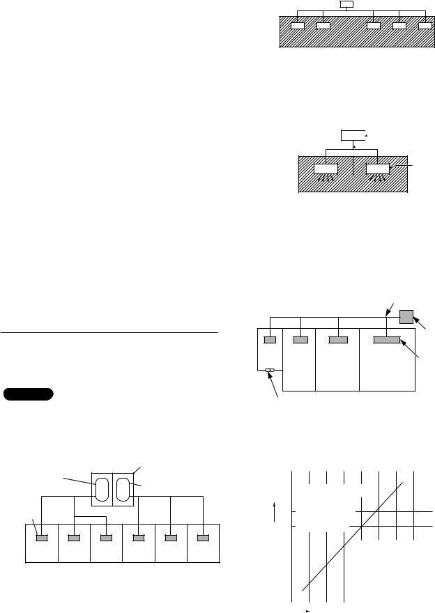
1.If there are 2 or more refrigerating systems in a single refrigerating device, the amount of refrigerant should be as charged in each independent device.
For the amount of charge in this example:
Outdoor unit
e.g., charged
amount (10 kg) e.g., charged amount (15 kg)
Indoor unit
Room A Room B Room C Room D Room E Room F
The possible amount of leaked refrigerant gas in rooms A, B and C is 10 kg.
The possible amount of leaked refrigerant gas in rooms D, E and F is 15 kg.
2.The standards for minimum room volume are as follows.
(1) No partition (shaded portion)
(2)When there is an effective opening with the adjacent room for ventilation of leaking refrigerant gas (opening without a door, or an opening 0.15% or larger than the respective floor spaces at the top or bottom of the door).
 Outdoor unit
 Refrigerant tubing
Indoor unit |
(3)If an indoor unit is installed in each partitioned room and the refrigerant tubing is interconnected, the smallest room of course becomes the object. But when mechanical ventilation is installed interlocked with a gas leakage detector in the smallest room where the density limit is exceeded, the volume of the next smallest room becomes the object.
|
|
Refrigerant tubing |
|
|
Outdoor unit |
Very |
|
|
small |
|
Indoor unit |
room |
|
|
|
|
|
Small |
Medium |
Large room |
room |
room |
|
Mechanical ventilation device – Gas leak detector
3.The minimum indoor floor space compared with the amount of refrigerant is roughly as follows: (When the ceiling is 2.7 m high)
40 |
|
|
Range below the |
||
m2 35 |
||
|
||
density limit |
30of 0.3 kg/m3 (countermeasures
space |
25 |
|
not needed) |
|
|
|
|
|
|
|
|
|
|
20 |
|
|
|
|
|
|
|
|
|
|
|
|
|
|
|
|
|
|
Range above |
|
|
||||||
|
|
|
|
|
|
|
|||||||
floor |
|
|
|
|
|
|
|
||||||
15 |
|
|
|
|
|
|
|
||||||
|
|
|
|
|
the density limit |
|
|
||||||
|
|
|
|
|
|||||||||
indoor |
10 |
|
|
|
|
|
of 0.3 kg/m3 |
|
|
||||
|
|
|
|
|
|
|
|
||||||
|
|
|
|
|
|
(countermeasures |
|
|
|||||
|
|
|
|
|
|
||||||||
Min. |
5 |
|
|
|
|
|
needed) |
|
|
|
|
|
|
|
|
|
|
|
|
|
|
|
|
|
|
|
|
|
0 |
|
|
|
|
|
|
|
|
|
|
|
|
|
|
10 |
20 |
|
30 |
|
kg |
||||||
|
|
|
|
|
|||||||||
Total amount of refrigerant
3

CONTENTS
Page
IMPORTANT . . . . . . . . . . . . . . . . . . . . . . . . . . . . . . 2
Please Read Before Starting
Check of Density Limit
1. GENERAL . . . . . . . . . . . . . . . . . . . . . . . . . . . . . 4
1-1. Tools Required for Installation (not supplied) 1-2. Type of Copper Tube and Insulation Material 1-3. Additional Materials Required for Installation
2. HOW TO INSTALL THE UNIT . . . . . . . . . . . . . .5
2-1. Duct for fresh air
3.TEST OF THE SYSTEM AND CONTROL OF THE AIR VOLUME TO THE OUTLET GRILLES . . . .7
|
|
|
Page |
4. |
ELECTRICAL WIRING . . . . . . . . . . . . . . . . . . |
. .8 |
|
|
4-1. |
General Precautions on Wiring |
|
|
4-2. Recommended Wire Length and Wire Diame- |
||
|
|
ter for Power Supply System |
|
|
4-3. Wiring System Diagrams |
|
|
5. |
HOW TO PROCESS TUBING . . . . . . . . . . . . . |
.12 |
|
|
5-1. Connecting the Refrigerant Tubing |
|
|
|
5-2. Connecting Tubing between Indoor and Out- |
||
|
|
door Units |
|
|
5-3. |
Insulating the Refrigerant Tubing |
|
|
5-4. |
Taping the Tubes |
|
|
5-5. |
Finishing the Installation |
|
6 |
APPENDIX . . . . . . . . . . . . . . . . . . . . . . . . . . . |
.16 |
|
1. GENERAL
This booklet briefly outlines where and how to install the air conditioning system. Please read over the entire set of instructions for the indoor unit and make sure all accessory parts listed are with the system before beginning.
1-1. Tools Required for Installation (not supplied)
1.Standard screwdriver
2.Phillips head screwdriver
3.Knife or wire stripper
4.Tape measure
5.Carpenter’s level
6.Sabre saw or key hole saw
7.Hacksaw
1-2. Type of Copper Tube and Insulation Material
If you wish to purchase these materials separately from a local source, you will need:
1.Deoxidized annealed copper tube for refrigerant tubing.
2.Foamed polyethylene insulation for copper tubes as required to precise length of tubing. Wall thickness of the insulation should be not less than 8 mm.
3.Use insulated copper wire for field wiring. Wire size varies with the total length of wiring. Refer to
4. Electrical Wiring for details.
8.Core bits
9.Hammer
10.Drill
11.Tube cutter
12.Tube flaring tool
13.Torque wrench
14.Adjustable wrench
15.Reamer (for deburring)
CAUTION |
Check local electrical codes |
|
and regulations before |
||
|
||
|
||
|
obtaining wire. Also, check |
|
|
any specified instructions |
|
|
or limitations. |
1-3. Additional Materials Required for Installation
1.Refrigeration (armored) tape
2.Insulated staples or clamps for connecting wire (See your local codes.)
3.Putty
4.Refrigeration tubing lubricant
5.Clamps or saddles to secure refrigerant tubing
6.Scale for weighing
4
2. HOW TO INSTALL THE UNIT
Minimum operation and maintenance area. (fig. 2-1)
300
|
A |
B |
|
|
|
7/9/12 |
1500 |
1100 |
16/18/22 |
1700 |
1100 |
|
|
|
Fig. 2-1
Find the space for the installation of the return air grille and mark the opening to do. Cut the falseceiling. (fig. 2-2)
Use rawl plug suitable to the ceiling consistence and four M10 threaded bars of suitable length (not supplied). (fig. 2- 3)
Mark on the ceiling the holes for the hanging rods, verify the distance of the centres. The value included in the brackets is referred to the model X18. (fig. 2-4)
Drill a 80 mm diameter hole, for the passage of refrigeration pipework, condensate pipework and electrical cable. Insert a PVC pipe in the wall. (fig. 2-5)
Secure the unit in position with locknuts and washers, level the unit, keeping the right distance from the falseceiling for the installation of return air grille. (fig. 2-6)
Foresee a removable panel of the falseceiling for servicing. (fig. 2-7)
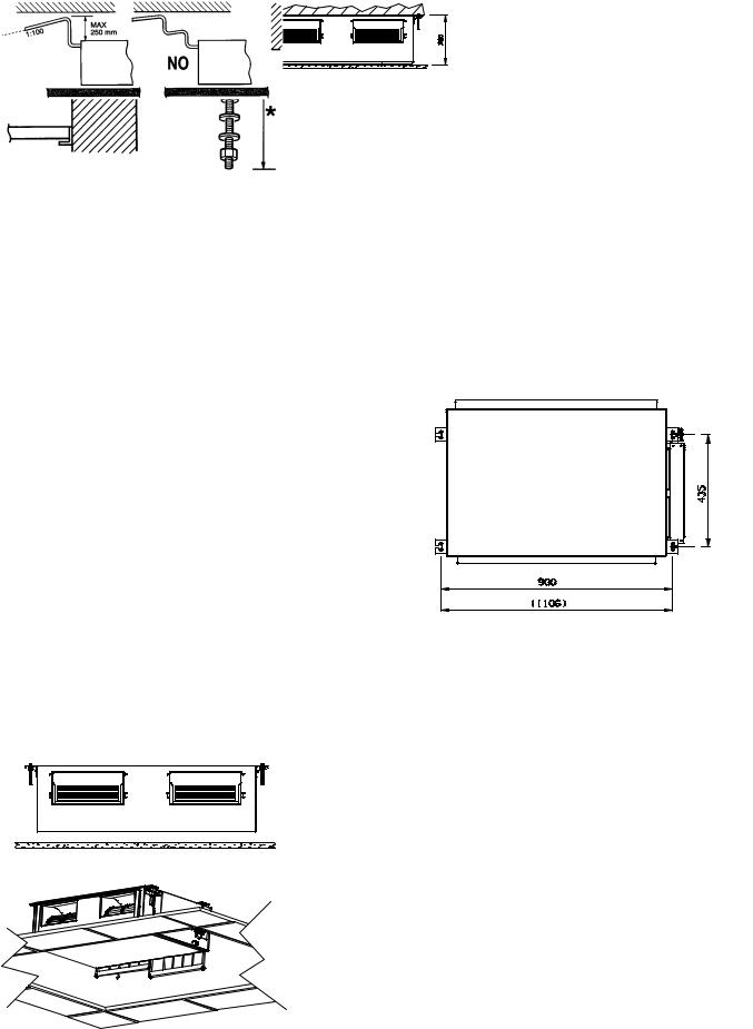
The unit is supplied with PVC hose from the condensate pump. Maximum pump lift is 250 mm over the unit. Convoy the condensate with a positive slope (min. 1:100) to the outside. The highest point in the condensate pipework should be as close to the unit as possible. This prevents a large volume of water draining back into the unit when it is switched off. (fig. 2-8)
Convoy the condensate to the outside with a positive slope, from a trap at the end if necessary. (fig. 2-9)
Fig. 2-5
Fig. 2-6
Fig. 2-7
Fig. 2-2
Fig. 2-3
Fig. 2-4
Fig. 2-8
Fig. 2-9
5

On the front and rear side of the unit a rectangular port (with flange) helps during duct mounting. (fig. 2-10)
Rear and front flange for the air intake. The value included in the brackets is referred to the model X18. (fig. 2-11)
Discarge air duct (optional accessory). Contact the After Sale Service. (fig. 2-12)
Remove the filter and pour, inside the condensate drain pan, 0.5 liter of water. Start the unit checking for proper drain pump operation. (fig. 2-13)
Fig. 2-11
2-1 Duct for fresh air
Outlet conduct
Intake coduct
False ceiling
Fig. 2-10
Air intake
Fig. 2-12
Fig. 2-13
2
1
There is a duct connection port for drawing in fresh air.
The supplementary fan motor for outside air intake has to be supplied separately and controlled by a bipolar ON-OFF switch with safety fuses.
Fresh air flow must be about 10% of the total air flow to avoid operating problems and noise.
•Open the knock-out hole , fix a 120 mm flange on the unit and connect the thermically insulated duct.
•Install an outside grille with filter inspection port to prevent dust and leaves from entering and fouling the indoor unit heat exchanger.
6
3. TEST OF THE SYSTEM AND CONTROL OF THE AIR VOLUME TO THE OUTLET GRILLES
The unit is prearranged to supply an external static pressure of about 5 mm. Too high resistances in the air distribution system can cause an exceedingly small air volume to the outlet grilles.
This trouble can be solved by increasing the fan speed as follows:
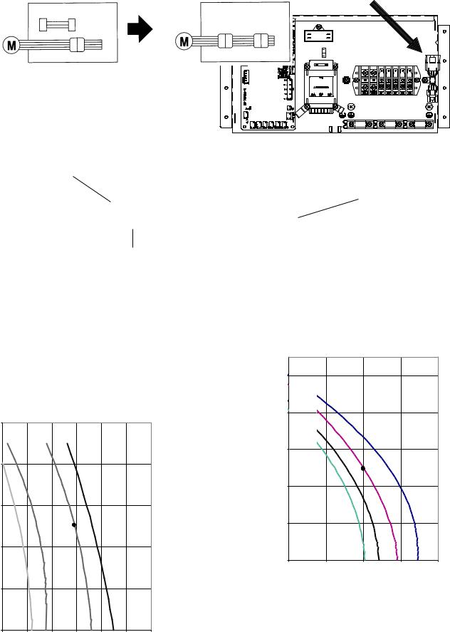
Open the cover of the electrical junction box. Take out the booster cable clamped in the box. (fig. 3-1)
Disconnect the fan motor plug in the electrical box and insert the booster cable as a cable extension between the motor plug and the socket from the PCB. The external static pressure will increase to 7 mm w.g. Check static pressure and air flow rate on the fan performance graph. (fig. 3-2)
Fig. 3-1
Booster cable
Booster cable
Fan motor
Fan motor
Connector motor cable (at the supply)
Fig. 3-2
H = High fan speed
L = Low fan speed
HH = Very high fan speed
M = Middle fan speed
16/18/22
10
(mmW.G.) |
8 |
|
|
|
|
|
|
|
|
|
|
|
|
|
|
PRESSURE |
6 |
|
|
|
|
|
|
|
|
|
|
|
|
|
|
STATIC |
|
|
|
|
HH |
|
|
4 |
|
M |
H |
|
|
|
|
|
|
|
|
|
|
||
EXTERNAL |
|
|
|
|
|
|
|
|
L |
|
|
|
|
|
|
|
|
|
|
|
|
|
|
|
2 |
|
|
|
|
|
|
|
0 |
|
|
|
|
|
|
|
300 |
500 |
700 |
900 |
1100 |
1300 |
1500 |
m3/h
|
|
|
7/9/12 |
|
|
|
10 |
|
|
|
|
(mmW.G.) |
8 |
|
|
|
|
|
|
|
|
|
|
PRESSURE |
6 |
|
|
|
|
|
|
|
HH |
|
|
STATIC |
|
|
|
|
|
4 |
|
H |
|
|
|
EXTERNAL |
|
|
M |
|
|
|
|
L |
|
|
|
2 |
|
|
|
|
|
|
|
|
|
|
|
|
0 |
|
|
|
|
|
200 |
400 |
600 |
800 |
1000 |
|
|
|
|
|
m3/h |
H: Standard supplied unit. Available fan speeds: Low-Midd- le-High (L - M - H). Max. static pressure: about 5 mm
HH:Unit with cable extension of the fan motor (booster cable). Available fan speeds: Middle-High-Very high (M - H - HH). Max. static pressure: about 7 mm
7
4. ELECTRICAL WIRING
4-1. General Precautions on Wiring
(1)Before wiring, confirm the rated voltage of the unit as shown on its nameplate, then carry out the wiring closely following the wiring diagram.
(2)Provide a power outlet to be used exclusively for each unit, and a power supply disconnect and circuit breaker for overcurrent protection should be provided in the exclusive line.
(3)To prevent possible hazards from insulation failure, the unit must be grounded.
(4)Each wiring connection must be done in accordance with the wiring system diagram. Wrong wiring may cause the unit to misoperate or become damaged.
(5)Do not allow wiring to touch the refrigerant tubing, compressor, or any moving parts of the fan.
(6)Unauthorized changes in the internal wiring can be very dangerous. The manufacturer will accept no responsibility for any damage or misoperation that occurs as a result of such unauthorized changes.
(7)Regulations on wire diameters differ from locality to locality. For field wiring rules, please refer to your LOCAL ELECTRICAL CODES before beginning.
You must ensure that installation complies with all relevant rules and regulations.
(8)To prevent malfunction of the air conditioner caused by electrical noise, care must be taken when wiring as follows:
●The remote control wiring and the inter-unit control wiring should be wired apart from the inter-unit power wiring.
●Use shielded wires for inter-unit control wiring between units and ground the shield on both sides.
(9)If the power supply cord of this appliance is damaged, it must be replaced by a repair shop appointed by the manufacture, because special purpose tools are required.
4-2. Recommended Wire Length and Wire Diameter for Power Supply System
Outdoor unit
|
|
(A) Power supply |
Time delay fuse or |
|
(A) Power supply |
Time delay fuse or |
||
|
|
Wire size |
Max. length |
circuit capacity |
|
Wire size |
Max. length |
circuit capacity |
SPW-CR604GDXH8 |
4 mm2 |
113 m |
15 A |
|
2.5 mm2 |
70 m |
16A |
|
SPW-CR704GDXH8 |
6 mm2 |
74 m |
30 A |
|
6 mm2 |
74 m |
35A |
|
SPW-CR904GDXH8 |
6 mm2 |
60 m |
35 A |
or |
6 mm2 |
60 m |
35A |
|
SPW-CR1154GDXH8 |
6 mm2 |
55 m |
40 A |
|
10 mm2 |
91 m |
50A |
|
SPW-CR704GDCH8 |
6 mm2 |
47 m |
35 A |
|
6 mm2 |
47 m |
35A |
|
SPW-CR904GDCH8 |
6 mm2 |
46 m |
40 A |
|
10 mm2 |
77 m |
50A |
|
SPW-CR1154GDCH8 |
6 mm2 |
39 m |
50 A |
|
10 mm2 |
65 m |
50A |
|
Indoor unit |
|
|
|
|
|
|
|
|
(B) Power supply |
Time delay fuse or |
|
|
|
|
|
||
2.5 mm2 |
circuit capacity |
|
|
|
|
|
|
|
Max. 130 m |
|
10 ~16A |
|
|
|
|
|
|
Control wiring
(C) Inter-unit (between outdoor and |
(D) Remote control wiring |
(E) Control wiring for group control |
indoor units) control wiring |
|
|
|
|
|
0.75 mm2 (AWG #18) |
0.75 mm2 (AWG #18) |
0.75 mm2 (AWG #18) |
Use shielded wiring* |
Use shielded wiring |
Use shielded wiring |
Max. 1,000 m |
Max. 500 m |
Max. 500 m (Total) |
|
|
|
|
|
|
NOTE |
|
(F) Inter-outdoor unit control wiring |
|
|
|
|
0.75 mm2 (AWG #18) |
|
|
|
|
* With ring-type wire terminal. |
|
Use shielded wiring |
|
|
Max. 500 m |
|
|
|
8
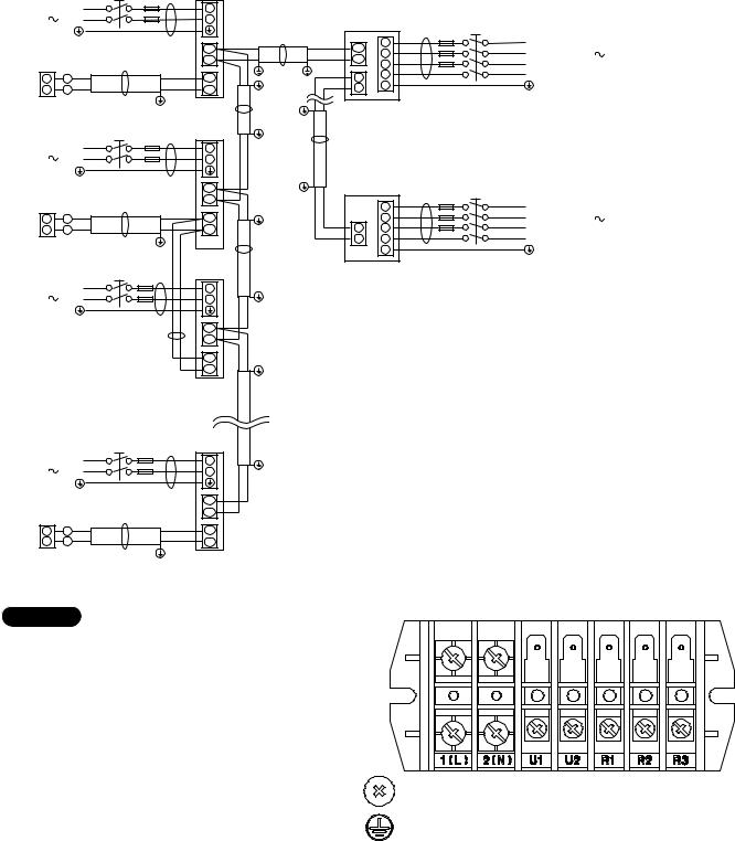
4-3. Wiring System Diagrams
Power supply |
L |
||
220-240V |
|
50Hz N |
|
|
|
|
Ground |
Remote |
|
|
D |
controller |
|
||
WHT |
1 |
|
1 |
BLK |
2 |
|
2 |
Power supply |
L |
||
220-240V |
|
50Hz N |
|
|
|
|
Ground |
Remote |
|
|
|
controller |
|
D |
|
WHT |
1 |
|
1 |
BLK |
2 |
|
2 |
Group control: |
|||
Power supply |
L |
||
220-240V |
|
50Hz N |
|
Ground
Power supply |
L |
||
220-240V |
|
50Hz N |
|
|
|
|
Ground |
Remote |
|
|
D |
controller |
|
||
WHT |
1 |
|
1 |
BLK |
2 |
|
2 |
Indoor unit (No. 1)
1
2
B |
|
C |
U1 |
|
|
|
|
|
|
U2 |
|
|
R1 |
Ground |
|
|
|
|
R2 |
Ground |
|
C |
|
|
|
|
|
Indoor |
Ground |
|
unit (No. 2) |
|
|
F |
|
|
1 |
|
|
|
|
|
2 |
|
B |
U1 |
|
|
|
|
|
U2 |
|
|
R1 |
|
|
R2 |
Ground |
|
|
|
|
C |
|
|
Indoor |
|
|
unit (No. 3) |
|
|
1 |
|
|
2 |
|
B U1
EU2
R1
R2
Ground
C 
Indoor unit (No. n)
1
2
B
U1
U2
R1
R2
Outdoor unit
INV unit
A
U1 |
1 |
|
2 |
||
U2 |
||
3 |
||
|
||
3 |
4 |
|
5 |
||
4 |
||
|
Inter-outdoor-unit control wiring
Outdoor unit
CS unit
A
1
2
3 3
4 4
5
Ground
L1 |
Power supply |
|
L2 |
||
380-415V-3N 50Hz |
||
L3 |
||
|
||
N |
|
|
Ground |
|
L1 |
Power supply |
|
L2 |
||
380-415V-3N 50Hz |
||
L3 |
||
|
||
N |
|
|
Ground |
|
NOTE
(1)Refer to Section 5-2. “Recommended Wire Length and Wire Diameter for Power Supply System” for the explanation of “A,” “B,” “C,” “D,” and “E,” in the above diagrams.
(2)The basic connection diagram of the indoor unit shows the 7P terminal board, so the terminal boards in your equipment may differ from the diagram.
(3)Refrigerant Circuit (R.C.) address should be set before turning the power on.
7P terminal board
1(L) |
2(N) |
U1 |
U2 |
R1 |
R2 |
power |
|
Inter-unit |
Remote |
||
supply |
|
control |
controller |
||
|
|
wiring |
|
|
|
9
CAUTION
(1)When linking outdoor units in a network (S-net link system), disconnect the terminal extended from the short plug (CN003, 2P Black, location: right bottom on the outdoor main control PCB) from all outdoor units except any one of the outdoor units.
(When shipping: In shorted condition.)
Otherwise the communication of S-net link system is not performed. For a system without link (no connection wiring between outdoor units), do not remove the short plug.
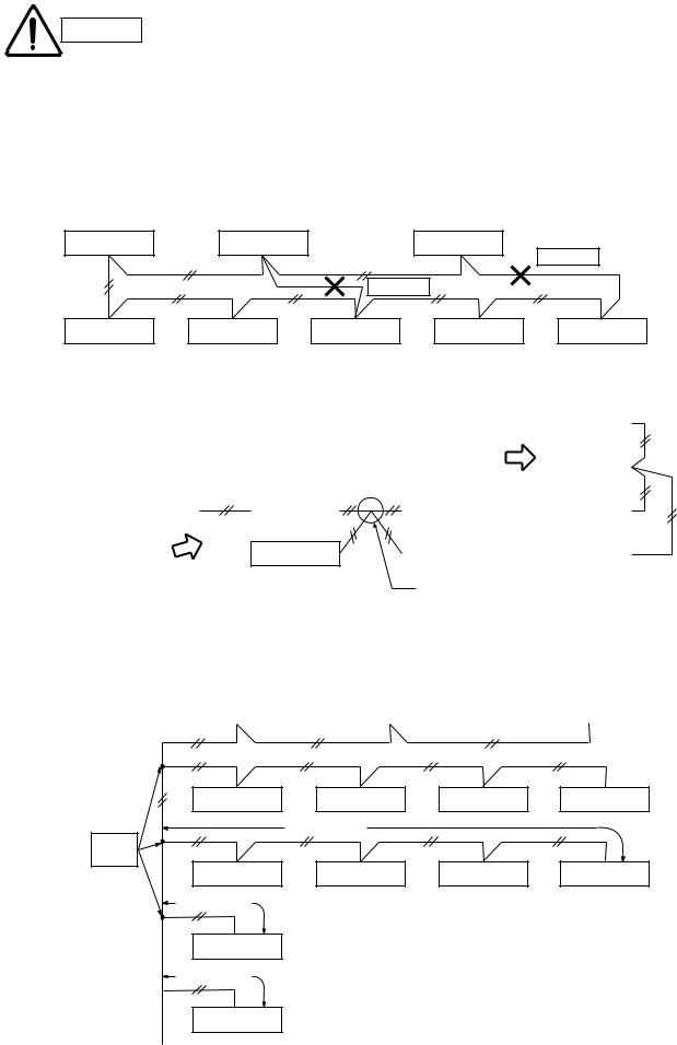
(2)Do not install the inter-unit control wiring in a way that forms a loop. (Fig. 4-1)
Outdoor unit |
Outdoor unit |
|
Outdoor unit |
|
|
|
|
|
Prohibited |
|
|
Prohibited |
|
|
Indoor unit |
Indoor unit |
Indoor unit |
Indoor unit |
Indoor unit |
Fig. 4-1
(3)Do not install inter-unit control wiring such as star branch wiring. Star branch wiring causes mis-address setting.
Outdoor unit |
|
Indoor unit |
|
|
|
NO |
Indoor unit |
|
Fig. 4-2
|
|
Outdoor unit |
NO |
|
|
|
||
Indoor unit |
||
|
|
|
Indoor unit |
|
Indoor unit |
|
|
|
|
|
|
Indoor unit |
|
Indoor unit |
|
|
|
Branch point |
|
|
(4)If branching the inter-unit control wiring, the number of branch points should be 16 or fewer. (Branches less than 1 m are not included in the total branch number.) (Fig. 4-3)
Outdoor unit |
|
Outdoor unit |
|
Outdoor unit |
|
|
|
|
|
Indoor unit |
Indoor unit |
Indoor unit |
Indoor unit |
|
more than 1 m |
|
|
Branch |
|
|
|
point |
|
|
|
Indoor unit |
Indoor unit |
Indoor unit |
Indoor unit |
16 or fewer
more than 1 m
Indoor unit
less than 1 m
Indoor unit
Fig. 4-3
10
(5)Use shielded wires for inter-unit control wiring
(c) and ground the shield on both sides, otherwise misoperation from noise may occur. (Fig. 4-4)
Connect wiring as shown in Section “4-3. Wiring System Diagrams.”
Loose wiring may cause
WARNING the terminal to overheat or result in unit malfunction.
A fire hazard may also exist. Therefore, ensure that all wiring is tightly connected.
When connecting each power wire to the terminal, follow the instructions on “How to connect wiring to the terminal” and fasten the wire securely with the fixing screw of the terminal plate.
How to connect wiring to the terminal
■ For stranded wiring
(1)Cut the wire end with cutting pliers, then strip the insulation to expose the stranded wiring about 10 mm and tightly twist the wire ends. (Fig. 4-5)
(2)Using a Phillips head screwdriver, remove the terminal screw(s) on the terminal plate.
(3)Using a ring connector fastener or pliers, securely clamp each stripped wire end with a ring pressure terminal.
(4)Place the ring pressure terminal, and replace and tighten the removed terminal screw using a screwdriver. (Fig. 4-6)
Shielded wire
Ground |
Ground |
Fig. 4-4
|
Stranded wire |
|
mm |
Ring |
|
10 |
||
pressure |
||
Strip |
||
terminal |
||
|
Fig. 4-5
Special
washer Screw
Ring pressure
terminal  Screw and Special washer
Wire |
Terminal plate |
|
Ring pressure terminal
Wire 
Fig. 4-6
11
 Loading...