


ENGLISH
LCD HDTV
Owner’s Manual
Table of Contents . . . . 4
ESPAÑOL
TV de LCD HDTV Manual de Instrucciones
Contenido . . . . . . . . . 22
FRANÇAIS
TVHD ACL
Manuel d’instructions
Table des matières . . 39
Need assistance?
Visit our Web site at
www.sanyoctv.com
or call toll free
1-800-877-5032
We can Help!
© 2008 Sanyo Manufacturing Corporation
Model Nos.: |
DP26648 |
Nos. de Modelo: |
DP32648 |
Nos de modèle : |
Welcome to the World of Sanyo
Thank you for purchasing this Sanyo LCD High-Definition Digital Television. You made an excellent choice for Performance, Reliability, Features, Value, and Styling.
Printed in Mexico SMC, February 2008
Impreso en México SMC, febrero 2008
Imprimé aux. Mexique SMC, février 2008
Part No. / No. de Parte / No de piece : 1JC6P1P0302--
|
|
|
|
|
CAUTION |
|
THIS SYMBOL INDICATES THAT DANGEROUS VOLTAGE CONSTITUTING A |
|
|
|
|
|
|
|
RISK OF ELECTRIC SHOCK IS PRESENT WITHIN THIS UNIT. |
|
RISK OF ELECTRIC SHOCK DO NOT OPEN |
||
|
|
|
|
|
|
|
|
CAUTION: TO REDUCE THE RISK OF ELECTRIC SHOCK, DO NOT REMOVE COVER (OR |
|
THIS SYMBOL INDICATES THAT THERE ARE IMPORTANT OPERATING AND |
|
BACK). NO USER-SERVICEABLE PARTS INSIDE. REFER SERVICING TO QUALIFIED SER- |
|
MAINTENANCE INSTRUCTIONS IN THE LITERATURE ACCOMPANYING THIS |
|
VICE PERSONNEL. |
|
UNIT. |
|
WARNING: TO REDUCE THE RISK OF FIRE OR ELECTRIC SHOCK, DO NOT EXPOSE THIS APPLIANCE TO RAIN OR MOISTURE.
IMPORTANT SAFETY INSTRUCTIONS
1.Read these instructions.
2.Keep these instructions.
3.Heed all warnings.
4.Follow all instructions.
5.Do not use this apparatus near water.
6.Clean only with dry cloth.
7.Do not block any ventilation openings. Install in accordance with the manufacturer’s instructions.
8.Do not install near any heat sources such as radiators, heat registers, stoves, or other apparatus (including amplifiers) that produce heat.
9.Do not defeat the safety purpose of the polarized or grounding-type plug. A polarized plug has two blades with one wider than the other. A grounding-type plug has two blades and a third grounding prong. The wide blade or the third prong are provided for your safety. If the provided plug does not fit fully into your outlet, consult an electrician for replacement of the obsolete outlet.
10.Protect the power cord from being walked on or pinched particularly at plugs, convenience receptacles, and the point where they exit from the apparatus.
11.Only use attachments/accessories specified by the manufacturer.
12.Use only with the cart, stand, tripod, bracket, or table specified by the manufacturer, or sold with the apparatus. When a cart is used, use caution when moving the cart/apparatus combination to avoid injury from tip-over.
13.Unplug this apparatus during lightning storms or when unused for long periods of time.
14.Refer all servicing to qualified service personnel. Servicing is required when the apparatus has been damaged in any way, such as power-supply cord or plug is damaged, liquid has been spilled or objects have fallen into the apparatus, the apparatus has been exposed to rain or moisture, does not operate normally, or has been dropped.
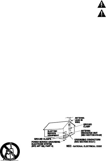
15.If an outside antenna is connected to the television equipment, be sure the antenna system is grounded so as to provide some protection against voltage surges and built up static charges. In the U.S. Selection 810-21 of the National Electrical Code provides information with respect to proper grounding of the mast and supporting structure, grounding of the lead-in wire to an antenna discharge unit, size of grounding conductors, location of antenna discharge unit, connection to grounding electrodes, and requirements for the grounding electrodes.
16.An outside antenna system should not be located in the vicinity of overhead power lines or other electrical light or power circuits, or where it can fall into such power lines or circuits. When installing an outside antenna system, extreme care should be taken to keep from touching such power lines or circuits as contact with them might be fatal.
EXAMPLE OF ANTENNA GROUNDING ACCORDING
TO NATIONAL ELECTRICAL CODE,ANSI/NFPA 70
“Note to CATV system installer:
This reminder is provided to call the CATV system installer’s attention to Article 820-40 of the NEC that provides guidelines for proper grounding and, in particular, specifies that the cable ground shall be connected to the grounding system of the building, as close to the point of cable entry as practical.”
17.Wall or Ceiling Mounting—The product should be mounted to a wall or ceiling only as recommended by the manufacturer.
18."Apparatus shall not be exposed to dripping or splashing and no objects filled with liquids, such as vases, shall be placed on the apparatus."
19.When the MAINS plug is used as the disconnect device, the disconnect device shall remain readily operable.
2 |
Need help? Visit our Web site at www.sanyoctv.com or Call 1-800-877-5032 |
FCC INFORMATION
This equipment has been tested and found to comply with the limits for a Class B digital device, pursuant to Part 15 of the FCC Rules. These limits are designed to provide reasonable protection against harmful interference in a residential installation. This equipment generates, uses and can radiate radio frequency energy and, if not installed and used in accordance with the instructions, may cause harmful interference to radio communications. However, there is no guarantee that interference will not occur in a particular installation. If this equipment does cause harmful interference to radio or television reception, which can be determined by turning the equipment off and on, the user is encouraged to try to correct the interference by one or more of the following measures:
–Reorient or relocate the receiving antenna.
–Increase the separation between the equipment and receiver.
–Connect the equipment into an outlet on a circuit different from that to which the receiver is connected.
–Consult the dealer or an experienced radio/TV technician for help.
CAUTION: FCC Regulations state that improper modifications or unauthorized changes to this unit may void the user’s authority to operate the unit.
TRADEMARKS
Manufactured under license from Dolby Laboratories. “Dolby” is a trademark of Dolby Laboratories.
“As an Energy Star® Partner, Sanyo Manufacturing Corporation has determined that this product meets the Energy Star® guidelines for energy efficiency.”
This symbol on the nameplate means the product is Listed by Underwriters’ Laboratories Inc. It is designed and manufactured to meet rigid U.L. safety standards against risk of fire, casualty and electrical hazards.
SPECIFICATIONS
Power Requirement: Source: AC 120V, 60Hz
AC Power Consumption (average):
PROTECTING THE LCD SCREEN
The screen can be damaged if it is not maintained properly. Do not use hard objects such as hard cloth or paper. Do not use exces-
sive pressure when cleaning the screen; excessive pressure can cause permanent discoloration or dark spots.
NEVER spray liquids on the screen.
 HANDLING PRECAUTIONS
•Handle by the cabinet only. Never touch the screen when handling.
•Excessive pressure on the screen can cause permanent discoloration or dark spots.
•Handling damage is not covered under warranty.
CONTAINS MERCURY LAMPS,
DISPOSE OF PROPERLY
DP26648 |
120 watts |
DP32648 |
160 watts |
Need help? Visit our Web site at www.sanyoctv.com or Call 1-800-877-5032 |
3 |
CONTENTS |
|
IMPORTANT SAFETY INSTRUCTIONS . . . . . . . . . . . |
. . . . 2 |
FCC INFORMATION . . . . . . . . . . . . . . . . . . . . . . . . . . . |
. . . . .3 |
TRADEMARKS . . . . . . . . . . . . . . . . . . . . . . . . . . . . . . . . |
. . . .3 |
PROTECTING THE LCD SCREEN . . . . . . . . . . . . . . . . . . |
. . . .3 |
PRECAUTIONS— |
|
Handling . . . . . . . . . . . . . . . . . . . . . . . . . . . . . . . . . . . |
. . . .3 |
Disposal . . . . . . . . . . . . . . . . . . . . . . . . . . . . . . . . . . . . |
. . . .3 |
SPECIFICATIONS . . . . . . . . . . . . . . . . . . . . . . . . . . . . . . |
. . . .3 |
CONTENTS . . . . . . . . . . . . . . . . . . . . . . . . . . . . . . . . . . . |
. . . .4 |
ASSEMBLY—ATTACHING THE TV STAND . . . . . . . . |
. . . .4 |
INSTALLATION— |
|
Positioning the LCD HDTV . . . . . . . . . . . . . . . . . . . . |
. . . .5 |
Wall Mounting (Optional) . . . . . . . . . . . . . . . . . . . . . |
. . . .5 |
GETTING STARTED— |
|
Precautions . . . . . . . . . . . . . . . . . . . . . . . . . . . . . . . . |
. . . .5 |
Remote Control Battery Installation . . . . . . . . . . . . |
. . . .5 |
Antenna Connections to off-air or cable . . . . . . . . |
. . . .5 |
Controls and Jacks . . . . . . . . . . . . . . . . . . . . . . . . . . |
. . . .6 |
Remote Control Operation . . . . . . . . . . . . . . . . . . . . |
. . . .7 |
Connections . . . . . . . . . . . . . . . . . . . . . . . . . . . . . . . . |
. . . .8 |
Power Connection / Initial Channel Search . . . . . |
. . . .9 |
ADVANCED AV CONNECTIONS— |
|
HDMI 1 / 2 . . . . . . . . . . . . . . . . . . . . . . . . . . . . . . . . . . |
. . .10 |
Digital Audio / Audio Out Jacks (Fixed Analog) |
. . . .10 |
PC CONNECTIONS . . . . . . . . . . . . . . . . . . . . . . . . . . . . . . . .11
PC Menu Navigation Map . . . . . . . . . . . . . . . . . . . . . . .11
PC MONITOR OPERATION—
PC Preparation . . . . . . . . . . . . . . . . . . . . . . . . . . . . . . . . .11
PC Monitor Setup . . . . . . . . . . . . . . . . . . . . . . . . . . . . . .11
PC Menu Operating Tips . . . . . . . . . . . . . . . . . . . . . . . .11
Manual Adjustments . . . . . . . . . . . . . . . . . . . . . . . . . . . .11
ON-SCREEN MENU OPERATION—
Menu Navigation Map . . . . . . . . . . . . . . . . . . . . . . . . . .12
Manual Channel Search . . . . . . . . . . . . . . . . . . . . . . . .12
Channel Scan Memory . . . . . . . . . . . . . . . . . . . . . . . . . .13
Adding Channels to Scan Memory . . . . . . . . . . . . .13
Deleting Channels from Scan Memory . . . . . . . . . .13
V-Guide (Parental Control)
V-Guide Operation . . . . . . . . . . . . . . . . . . . . . . . . . . .14
V-Guide Operation (Advanced) . . . . . . . . . . . . . . . .15
Picture / Sound Adjustment
Adjusting the Picture / Sound Manually . . . . . . . . .16
Advanced Picture / Sound Adjustments . . . . . . . . .16
Digital Caption . . . . . . . . . . . . . . . . . . . . . . . . . . . . . . . . .17
Menu Language . . . . . . . . . . . . . . . . . . . . . . . . . . . . . . . .17
Energy (power) Saver . . . . . . . . . . . . . . . . . . . . . . . . . . .17
HELPFUL HINTS–Problems/Solutions . . . . . . . . . . . . . . .18
WARRANTY . . . . . . . . . . . . . . . . . . . . . . . . . . . . . . . . . . . . . .19
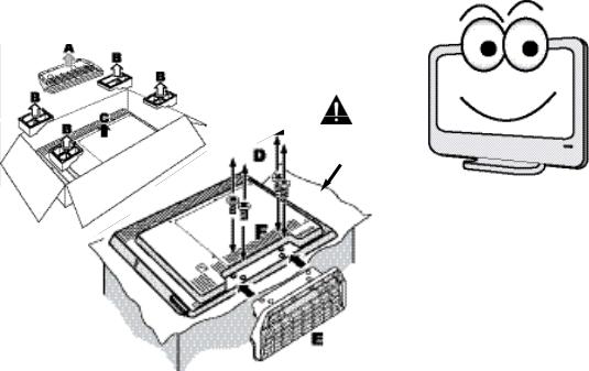
ASSEMBLY—ATTACHING THE TV STAND
NOTE: Skip this Step if you are wall-mounting the unit.
Tools Needed: Phillips screwdriver (remove screws from stand mounting inserts [D] before installing stand base.)
Padded
Surface
Hello! I’m your new Sanyo Widescreen LCD HDTV. Don’t plug me in just yet! Please read this manual carefully so you can learn about my many features, such as, my integrated HD Tuner, V-Guide control, Digital Channels, my PC Input and many more...
4 |
Need help? Visit our Web site at www.sanyoctv.com or Call 1-800-877-5032 |
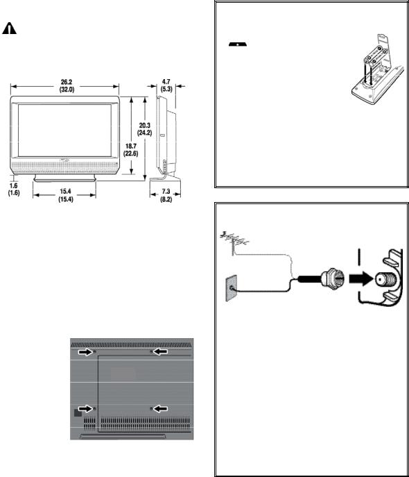
INSTALLATION
POSITIONING THE LCD HDTV
 Always use a firm-flat surface when positioning your HDTV. Do not position the unit in a confined area. Allow adequate space for proper ventilation.
DP26648
(DP32648)
GETTING STARTED
1Install supplied batteries in the Remote.
(2 ”AAA” eneloop Ni-MH rechargeable batteries)
 PRECAUTIONS
Do not use rechargeables together with dry cells, other types, mixed new and old, or batteries with different charge levels.
Do not expose the Remote or batteries to moisture or heat.
Match the “+” and “–” signs on the batteries with marks inside the Remote Control.
For eneloop battery recharging, please refer to your battery charger’s instructions (battery charger not included).
 Please recycle used up rechargeable batteries.
For more information visit: www.eneloopusa.com
NOTE: All dimensions are in inches.
WALL MOUNTING (OPTIONAL)
Use the screws that are threaded into the standmounting inserts on the back of your HDTV to secure it to a wall mounting kit.
NOTE:Wall Mounting kit is not supplied.
VESA standard interface: 200 x 200
Wall Mounting
Inserts
Mounting screws measurements:
M6 Diameter, Length—12mm (min.) 16mm (max.)
2 Antenna Connection for off-air signals
ANALOG / DIGITAL
ANTENNA IN
ANTENNA
OR
CABLE
THE TUNER IN THIS HDTV CAN RECEIVE:
a. Digital and Analog off-air signals from an antenna.
OR
b.Analog or ClearQAM cable channels from a direct Cable TV connection.
NOTES: You must use the on-screen MENU to Search for ClearQAM Cable channels. (See page 12.)
For the best picture, connect your Cable box or Satellite receiver to HDMI1, 2, or component jacks (Video2 or 3).
This HDTV can receive ANY unscrambled RF signal being broadcast.
Need help? Visit our Web site at www.sanyoctv.com or Call 1-800-877-5032 |
5 |

GETTING STARTED—CONTROLS AND JACKS
RIGHT-SIDE
PANEL
Power key
Volume
– + keys


Channel  ▼▲ keys
S-Video Input (VIDEO1), PAGE 8—To enhance video detail use the S-Video jack instead of the Video jack, if available on your external equipment. (An S-Video connection will override a connection to the Video1 input jack.)

Digital Audio Output (Coaxial), PAGE 10—Use a Phono-Type (Coaxial) Digital Audio Out Cable to connect Digital Audio Output to an advanced stereo home theater system equipped with Dolby® Digital 5.1.
Component Video Input (VIDEO2 or VIDEO3), PAGE 8—Connect digital video equipment to the Video Green (Y), Blue (Pb), Red (Pr) jacks, and matching Audio White (L ) and Red (R) jacks. These jacks will automatically detect the type of signal being received.
Stereo Audio Out (L/R) Jacks, PAGE 10—
Connect stereo audio equipment to these jacks.
PC Input (15-Pin Monitor and Mini Stereo Audio) Page 11—Connect computer and audio outputs to these terminals.
•MONITOR RGB (D-SUB)
•AUDIO R/L (Stereo Mini Jack)
6 |
Need help? Visit our Web site at www.sanyoctv.com |

LEFT-SIDE PANEL
Analog / Digital Antenna Input, PAGE 5—
Connect an RF antenna or Analog Cable system to this jack.
AV Input (VIDEO1), PAGE 8—Connect analog video equipment here.
HDMI Input (INPUT1 or INPUT2), PAGE 10—
An all digital AV interface that accepts uncompressed video signals for the very best picture possible. HDMI supports HDCP copy protection, allowing transmission of copy-protected digital content. The signal can also include Dolby® Digital or PCM audio, when available.
or Call 1-800-877-5032
 Loading...