


C1271
TECHNICAL & SERVICE MANUAL
KS0971 + C0971
+ CL0971
FILE NO.
KS1271 + C1271
+ CL1271
Destination: North America
DC INVERTER SPLIT SYSTEM AIR CONDITIONER
Indoor Model No.
KS0971
KS1271
Indoor Unit
Product Code No.
1 852 099 81
1 852 099 82
Outdoor Model No.
C0971
C1271
CL0971
CL1271
Product Code No.
1 852 330 23
1 852 330 24
1 852 330 25
1 852 330 26
Outdoor Unit
KS0971
KS1271
IMPORTANT
These air conditioners employ new
refrigerant R410A.
Pay special attention when
servicing the unit.
C0971
C1271
CL0971
CL1271
REFERENCE NO. SM700655-05
Important!
Please Read Before Starting
This air conditioning system meets strict safety and operating
standards. As the installer or service person, it is an
important part of your job to install or service the system so it
operates safely and efficiently.
For safe installation and trouble-free operation, you must:
Carefully read this instruction booklet before beginning.
Follow each installation or repair step exactly as shown.
Observe all local, state, and national electrical codes.
Pay close attention to all warning and caution notices given
in this manual.
This symbol refers to a hazard or
WARNING
CAUTION
If Necessary, Get Help
These instructions are all you need for most installation
sites and maintenance conditions. If you require help for
a special problem, contact our sales/service outlet or
your certified dealer for additional instructions.
In Case of Improper Installation
The manufacturer shall in no way be responsible for
improper installation or maintenance service, including
failure to follow the instructions in this document.
SPECIAL PRECAUTIONS
unsafe practice which can result
in severe personal injury or death.
This symbol refers to a hazard
or unsafe practice which can
result in personal injury or
product or property damage.
When Transporting
Be careful when picking up and moving the indoor and
outdoor units. Get a partner to help, and bend your knees
when lifting to reduce strain on your back. Sharp edges or thin
aluminum fins on the air conditioner can cut your fingers.
When Installing
In a Ceiling or Wall
Make sure the ceiling/wall is strong enough to hold the unit’s
weight. It may be necessary to construct a strong wood or
metal frame to provide added support.
In a Room
Properly insulate any tubing run inside a room to prevent
"sweating" that can cause dripping and water damage to walls
and floors.
In Moist or Uneven Locations
Use a raised concrete pad or concrete blocks to provide a
solid, level foundation for the outdoor unit. This prevents
water damage and abnormal vibration.
In an Area with High Winds
Securely anchor the outdoor unit down with bolts and a metal
frame. Provide a suitable air baffle.
In a Snowy Area (for Heat Pump-type Systems)
Install the outdoor unit on a raised platform that is higher than
drifting snow. Provide snow vents.
When Connecting Refrigerant Tubing
•
Use the flare method for connecting tubing.
•
Apply refrigerant lubricant to the matching surfaces of the
flare and union tubes before connecting them, then tighten
the nut with a torque wrench for a leak-free connection.
•
Check carefully for leaks before starting the test run.
When Servicing
WARNING
•
Do not supply power to the unit until all wiring and tubing
are completed or reconnected and checked.
•
Highly dangerous electrical voltages are used in this
system. Carefully refer to the wiring diagram and these
instructions when wiring. Improper connections and
inadequate grounding can cause accidental injury or death.
•
Ground the unit following local electrical codes.
•
Connect all wiring tightly. Loose wiring may cause
overheating at connection points and a possible fire
hazard.
When Wiring
ELECTRICAL SHOCK CAN CAUSE
SEVERE PERSONAL INJURY OR DEATH.
ONLY A QUALIFIED, EXPERIENCED
ELECTRICIAN SHOULD ATTEMPT TO
WIRE THIS SYSTEM.
•
Turn the power off at the main power box (mains) before
opening the unit to check or repair electrical parts and
wiring.
•
Keep your fingers and clothing away from any moving parts.
•
Clean up the site after you finish, remembering to check
that no metal scraps or bits of wiring have been left inside
the unit being serviced.
Others
CAUTION
Ventilate any enclosed areas when installing or testing the
•
refrigeration system. Escaped refrigerant gas, on contact
with fire or heat, can produce dangerously toxic gas.
Confirm upon completing installation that no refrigerant gas
•
is leaking. If escaped gas comes in contact with a stove,
gas water heater, electric room heater or other heat source,
it can produce dangerously toxic gas.
2

Table of Contents
Page
1. OPERATING RANGE
2. SPECIFICATIONS
2-1. Unit Specifications
2-2. Major Component Specifications
2-3. Other Component Specifications
3. DIMENSIONAL DATA
4. REFRIGERANT FLOW DIAGRAM
4-1. Refrigerant Flow Diagram
5. PERFORMANCE DATA
5-1. Te mperature Charts
5-2. Cooling Capacity
5-3. Cooling Capacity (Low Ambient)
5-4. Air Throw Distance Charts
6. ELECTRICAL DATA
6-1. Electrical Characteristics
6-2. Electric Wiring Diagrams
...................................................................................................................
.............................................................................................................
.....................................................................................................................
............................................................................................................
.................................................................................................................
....................................................................................................
....................................................................................................
.......................................................................................
.......................................................................................
...................................................................................................
........................................................................................
.................................................................................................
5
6
10
16
17
19
20
24
26
28
30
32
7. MAINTENANCE
7-1. Address Setting of the Remote Control Unit
7-2. Disconnecting and Connecting Positive Connector for Outdoor Unit
8. FUNCTIONS
8-1. Operation Functions
8-2. Protective Functions
9. TROUBLESHOOTING
9-1. Precautions before Performing Inspection or Repair
9-2. Method of Self-Diagnostics
9-3. Checking the Indoor and Outdoor Units
9-4. Trouble Diagnosis of Fan Motor
9-5. Noise Malfunction and Electromagnetic Interference
...........................................................................................................
...........................................................................................................
.................................................................................................
..........................................................................................
.......................................................................
...........................................................
..............................................................................
..........................................................
..................................
35
36
37
39
40
40
42
46
47
3

10. CHECKING ELECTRICAL COMPONENTS
10-1. Measurement of Insulation Resistance
10-2. Checking Continuity of Fuse on PCB Ass'y
11. REFRIGERANT R410A:
SPECIAL PRECAUTIONS WHEN SERVICING UNIT
11-1. Characteristics of New Refrigerant R410A
11-2. Checklist before Servicing
11-3. Tools Specifically for R410A
11-4. Tubing Installation Procedures
11-5. In Case of Compressor Malfunction
11-6. In Case Refrigerant is Leaking
11-7. Charging Additional Refrigerant
11-8. Retro-Fitting Existing Systems
...................................................................................................
................................................................................................
............................................................................................
....................................................................................
............................................................................................
..........................................................................................
............................................................................................
...............................................................................
.........................................................................
.........................................................................
Page
48
49
50
51
52
52
53
55
56
56
APPENDIX A INSTRUCTION MANUAL
..........................................................................................
APPENDIX B INSTALLATION INSTRUCTIONS
.............................................................................
A-1
A-2
4
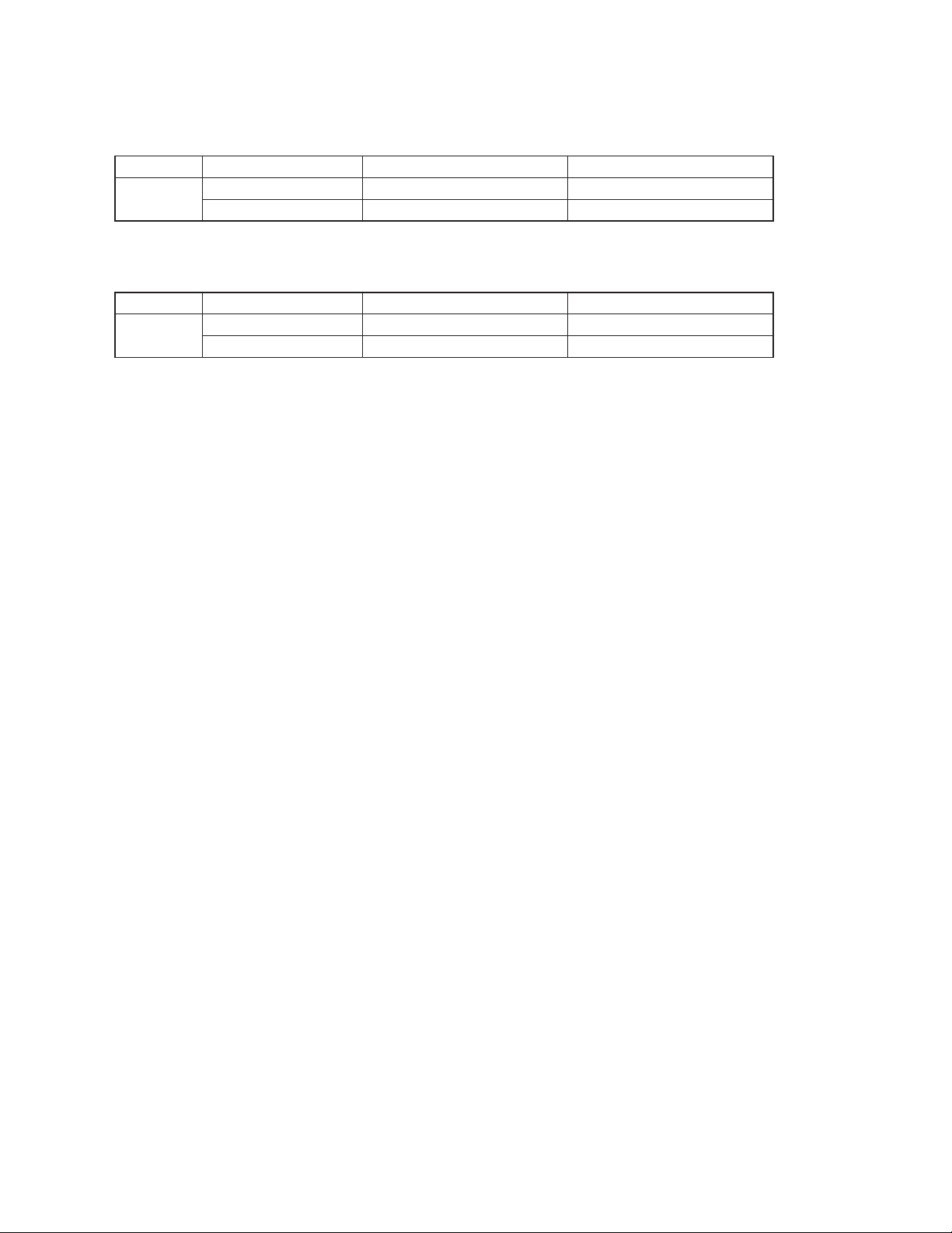
1. OPERATING RANGE
Models : KS0971 + C0971
KS1271 + C1271
Temperature Indoor Air Intake Temp. Outdoor Air Intake Temp.
Cooling
Models : KS0971 + CL0971
KS1271 + CL1271
Cooling
Maximum
Minimum
Temperature Indoor Air Intake Temp. Outdoor Air Intake Temp.
Maximum
Minimum
95 °F D.B. / 71 °F W.B.
67 °F D.B. / 57 °F W.B.
95 °F D.B. / 71 °F W.B.
67 °F D.B. / 57 °F W.B.
115 °F D.B.
67 °F D.B.
115 °F D.B.
0 °F D.B.
5
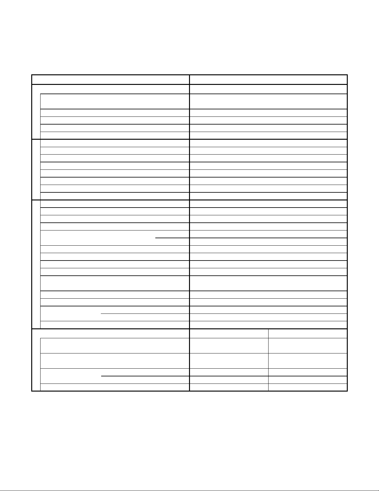
2. SPECIFICATIONS
2-1. Unit Specifications
Indoor Unit KS0971
Outdoor Unit C0971
Remarks: Rating conditions are:
Cooling: Indoor air temperature 80°F D.B. / 67°F W.B.
Outdoor air temperature 95°F D.B. / 75°F W.B.
DATA SUBJECT TO CHANGE WITHOUT NOTICE.
Vertical
dB-A
dB-A
Indoor : Hi/Me/Lo/Qt*
Outdoor : Hi
Air Filter
Compressor
Refrigerant / Amount charged at shipment Ibs (g)
Refrigerant Control
7.6
750
( 2.5 to 7.6 )
( 250 to 750 )
9,000
2.65
( 3,000 to 9,000 )
( 0.9 to 2.65 )
Shipping Volume
Cooling
7,650
1,350
Net
Shipping
Package Dimensions
Weight
Height × Width × Depth
Height × Width × Depth
Ibs (kg)
Ibs (kg)
cu.ft (m
3
)
(mm)
inch
(mm)
115V Single-Phase 60Hz
inch
104 to 126
Dimensions & Weight
(*Qt = Quiet mode)
Refrigerant Tubing Connections
Unit Dimensions
Operation Sound
Electrical Rating
Sensible Capacity
Latent Capacity
WPower Input
V
A
Available Voltage Range
Running Amperes
Refrigerant Tube Kit / Accessories
Narrow tube
Wide tube
Refrigerant inch (mm)
Tube Diameter inch (mm)
19.8
24.3
2.82
(9.0)
(11.0)
(0.08)
72.8
79.4
6.35
(33.0)
(36.0)
(0.18)
23-5/8 × 33-11/16 × 14-1/4
(600 × 856 × 362)
(285 × 825 × 189) (548 × 720 × 265)
10-1/32 × 35-7/16 × 13-25/32
(255 × 900 × 350)
Outdoor UnitIndoor Unit
11-7/32 × 32-15/32 × 7-7/16 21-9/16 × 28-11/32 × 10-7/16
1/4 (6.35)
3/8 (9.52)
ft (m)Max. allowable tubing length at shipment
Flare Type
25 (7.5)
34 / 31 / 28 / 23
46
R410A / 2.09 (950)
Electric Expansion Valve
Washable, Anti-Mold
DC Rotary (Inverter)
Manual
Auto
Timer
Indoor / OutdoorFan Speeds
24-Hour ON or OFF Timer, 1-Hour OFF Timer
Auto and 3 steps / Auto (Hi, Me, Lo)
Airflow Direction (Indoor) Horizontal
Controls / Temperature Control
Control Unit
Microprocessor / I.C. Thermister
Wireless Remote Control Unit
Features
Compressor Locked Rotor Amperes
Optional / Air Clean Filter
BTU/h
Performance
%Power Factor 86
A20
Voltage Rating
BTU/h
kW
Total Capacity
BTU/h
SEER BTU/Wh 16
282 (480)Air Circulation (High) ft3/min (m3/h)
3.4Moisture Removal (High) Pints/h
EER BTU/h/W 12
Fuse or Circuit Breaker Capacity A20
6

Indoor Unit KS1271
Outdoor Unit C1271
Voltage Rating
Total Capacity
Sensible Capacity
Latent Capacity
BTU/h
kW
BTU/h
BTU/h
115V Single-Phase 60Hz
11,900
3.5
Performance
Available Voltage Range
Running Amperes
V
A
WPower Input
10.9
1,090
%Power Factor 87
EER BTU/h/W 10.9
SEER BTU/Wh 17
Compressor Locked Rotor Amperes
Electrical Rating
A20
Fuse or Circuit Breaker Capacity A20
Controls / Temperature Control
Control Unit
Timer
Indoor / OutdoorFan Speeds
Microprocessor / I.C. Thermister
Wireless Remote Control Unit
24-Hour ON or OFF Timer, 1-Hour OFF Timer
Auto and 3 steps / Auto (Hi, Me, Lo)
Airflow Direction (Indoor) Horizontal
Vertical
Air Filter
Compressor
Refrigerant / Amount charged at shipment Ibs (g)
Features
Refrigerant Control
Operation Sound
(*Qt = Quiet mode)
Indoor : Hi/Me/Lo/Qt*
Outdoor : Hi
dB-A
dB-A
Washable, Anti-Mold
DC Rotary (Inverter)
R410A / 2.43 (1,100)
Electric Expansion Valve
36 / 33 / 29 / 25
Refrigerant Tubing Connections
ft (m)Max. allowable tubing length at shipment
Refrigerant inch (mm)
Tube Diameter inch (mm)
Refrigerant Tube Kit / Accessories
Narrow tube
Wide tube
Optional / Air Clean Filter
Unit Dimensions
Height × Width × Depth
Package Dimensions
Height × Width × Depth
Weight
Dimensions & Weight
Shipping Volume
Net
Shipping
inch
(mm)
inch
(mm)
Ibs (kg)
Ibs (kg)
cu.ft (m
11-7/32 × 32-15/32 × 7-7/16 21-9/16 × 28-11/32 × 10-7/16
(285 × 825 × 189) (548 × 720 × 265)
10-1/32 × 35-7/16 × 13-25/32
(255 × 900 × 350)
19.8
(9.0)
24.3
(11.0)
3
)
2.82
(0.08)
DATA SUBJECT TO CHANGE WITHOUT NOTICE.
Cooling
( 3,000 to 11,900 )
( 0.9 to 3.5 )
9,100
2,800
294 (500)Air Circulation (High) ft3/min (m3/h)
4.26Moisture Removal (High) Pints/h
104 to 126
( 2.5 to 10.9 )
( 250 to 1,090 )
Manual
Auto
47
Flare Type
25 (7.5)
1/4 (6.35)
3/8 (9.52)
Outdoor UnitIndoor Unit
23-5/8 × 33-11/16 × 14-1/4
(600 × 856 × 362)
75.0
81.6
6.35
(34.0)
(37.0)
(0.18)
Remarks: Rating conditions are:
Cooling: Indoor air temperature 80°F D.B. / 67°F W.B.
Outdoor air temperature 95°F D.B. / 75°F W.B.
7

Indoor Unit KS0971
Outdoor Unit CL0971
Voltage Rating
Total Capacity
Sensible Capacity
Latent Capacity
BTU/h
kW
BTU/h
BTU/h
115V Single-Phase 60Hz
9,000
2.65
Performance
Available Voltage Range
Running Amperes
V
A
WPower Input
7.6
750
%Power Factor 86
EER BTU/h/W 12
SEER BTU/Wh 16
Compressor Locked Rotor Amperes
Electrical Rating
A20
Fuse or Circuit Breaker Capacity A20
Controls / Temperature Control
Control Unit
Timer
Indoor / OutdoorFan Speeds
Microprocessor / I.C. Thermister
Wireless Remote Control Unit
24-Hour ON or OFF Timer, 1-Hour OFF Timer
Auto and 3 steps / Auto (Hi, Me, Lo)
Airflow Direction (Indoor) Horizontal
Vertical
Air Filter
Compressor
Refrigerant / Amount charged at shipment Ibs (g)
Features
Refrigerant Control
Operation Sound
(*Qt = Quiet mode)
Indoor : Hi/Me/Lo/Qt*
Outdoor : Hi
dB-A
dB-A
Washable, Anti-Mold
DC Rotary (Inverter)
R410A / 2.09 (950)
Electric Expansion Valve
34 / 31 / 28 / 23
Refrigerant Tubing Connections
ft (m)Max. allowable tubing length at shipment
Refrigerant inch (mm)
Tube Diameter inch (mm)
Refrigerant Tube Kit / Accessories
Narrow tube
Wide tube
Optional / Air Clean Filter
Unit Dimensions
Height × Width × Depth
Package Dimensions
Height × Width × Depth
Weight
Dimensions & Weight
Shipping Volume
Net
Shipping
inch
(mm)
inch
(mm)
Ibs (kg)
Ibs (kg)
cu.ft (m
11-7/32 × 32-15/32 × 7-7/16 21-9/16 × 28-11/32 × 10-7/16
(285 × 825 × 189) (548 × 720 × 265)
10-1/32 × 35-7/16 × 13-25/32
(255 × 900 × 350)
19.8
(9.0)
24.3
(11.0)
3
)
2.82
(0.08)
DATA SUBJECT TO CHANGE WITHOUT NOTICE.
Cooling
( 3,000 to 9,000 )
( 0.9 to 2.65 )
7,650
1,350
282 (480)Air Circulation (High) ft3/min (m3/h)
3.4Moisture Removal (High) Pints/h
104 to 126
( 2.5 to 7.6 )
( 250 to 750 )
Manual
Auto
46
Flare Type
25 (7.5)
1/4 (6.35)
3/8 (9.52)
23-5/8 × 33-11/16 × 14-1/4
(600 × 856 × 362)
Outdoor UnitIndoor Unit
72.8
79.4
6.35
(33.0)
(36.0)
(0.18)
Remarks: Rating conditions are:
Cooling: Indoor air temperature 80°F D.B. / 67°F W.B.
Outdoor air temperature 95°F D.B. / 75°F W.B.
8
Indoor Unit KS1271
Outdoor Unit CL1271
Voltage Rating
Total Capacity
Sensible Capacity
Latent Capacity
BTU/h
kW
BTU/h
BTU/h
115V Single-Phase 60Hz
11,900
3.5
Performance
Available Voltage Range
Running Amperes
V
A
WPower Input
10.9
1,090
%Power Factor 87
EER BTU/h/W 10.9
SEER BTU/Wh 17
Compressor Locked Rotor Amperes
Electrical Rating
A20
Fuse or Circuit Breaker Capacity A20
Controls / Temperature Control
Control Unit
Timer
Indoor / OutdoorFan Speeds
Microprocessor / I.C. Thermister
Wireless Remote Control Unit
24-Hour ON or OFF Timer, 1-Hour OFF Timer
Auto and 3 steps / Auto (Hi, Me, Lo)
Airflow Direction (Indoor) Horizontal
Vertical
Air Filter
Compressor
Refrigerant / Amount charged at shipment Ibs (g)
Features
Refrigerant Control
Operation Sound
(*Qt = Quiet mode)
Indoor : Hi/Me/Lo/Qt*
Outdoor : Hi
dB-A
dB-A
Washable, Anti-Mold
DC Rotary (Inverter)
R410A / 2.43 (1,100)
Electric Expansion Valve
36 / 33 / 29 / 25
Refrigerant Tubing Connections
ft (m)Max. allowable tubing length at shipment
Refrigerant inch (mm)
Tube Diameter inch (mm)
Refrigerant Tube Kit / Accessories
Narrow tube
Wide tube
Optional / Air Clean Filter
Unit Dimensions
Height × Width × Depth
Package Dimensions
Height × Width × Depth
Weight
Dimensions & Weight
Shipping Volume
Net
Shipping
inch
(mm)
inch
(mm)
Ibs (kg)
Ibs (kg)
cu.ft (m
11-7/32 × 32-15/32 × 7-7/16 21-9/16 × 28-11/32 × 10-7/16
(285 × 825 × 189) (548 × 720 × 265)
10-1/32 × 35-7/16 × 13-25/32
(255 × 900 × 350)
19.8
(9.0)
24.3
(11.0)
3
)
2.82
(0.08)
DATA SUBJECT TO CHANGE WITHOUT NOTICE.
Cooling
( 3,000 to 11,900 )
( 0.9 to 3.5 )
9,100
2,800
294 (500)Air Circulation (High) ft3/min (m3/h)
4.26Moisture Removal (High) Pints/h
104 to 126
( 2.5 to 10.9 )
( 250 to 1,090 )
Manual
Auto
47
Flare Type
25 (7.5)
1/4 (6.35)
3/8 (9.52)
Outdoor UnitIndoor Unit
23-5/8 × 33-11/16 × 14-1/4
(600 × 856 × 362)
75.0
81.6
6.35
(34.0)
(37.0)
(0.18)
Remarks: Rating conditions are:
Cooling: Indoor air temperature 80°F D.B. / 67°F W.B.
Outdoor air temperature 95°F D.B. / 75°F W.B.
9

2-2. Major Component Specifications
2-2-1. Indoor Unit
Indoor Unit KS0971
Control PCB
Part No.
Controls
Control Circuit Fuse
CB-KS0971
Microprocessor
250V 3A
Remote Control Unit
Fan
Type
Q'ty ... Dia. and Length
Fan Motor
Type
Model ... Q'ty
No. of Poles
Rough Measure RPM (Cool)
Nominal Output
Coil Resistance
(Ambient Temp. 68 °F (20 °C))
Safety Device
Type
Operating Temp.
Run Capacitor Micro F
Flap Motor
Type Stepping Motor
Model
Rating
Coil Resistance Ohm
(Ambient Temp. 77 °F (25 °C))
inch (mm)
W
Ohm
Open °F (°C)
Close °F (°C)
VAC
1 ... D3-11/16 / L24-31/32 (D94/L634)
Each Pair of Terminal : 400 +/- 7%
RCS-4VPIS4U
IBH-884-076 ... 1
BRN-WHT : 57.9
RED-WHT : 55.2
Thermal Fuse
Cross-Flow
AC Motor
4
1,200
16
266 (130)
-
4.5
250
MP24Z3
DC 12V
Heat Exchanger Coil
Coil
Rows
Fins per inch
ft
2
(m2)
Aluminum Plate Fin / Copper Tube
2
19.5
2.02 (0.188) Face Area
DATA SUBJECT TO CHANGE WITHOUT NOTICE.
10
Indoor Unit KS1271
Control PCB
Part No.
Controls
Control Circuit Fuse
CB-KS1271
Microprocessor
250V 3A
Remote Control Unit
RCS-4VPIS4U
Fan
Type
Q'ty ... Dia. and Length
inch (mm)
1 ... D3-11/16 / L24-31/32 (D94/L634)
Fan Motor
Type
Model ... Q'ty
IBH-884-076 ... 1
No. of Poles
Rough Measure RPM (Cool)
Nominal Output
Coil Resistance
(Ambient Temp. 68 °F (20 °C))
W
Ohm
BRN-WHT : 57.9
RED-WHT : 55.2
Safety Device
Type
Operating Temp.
Open °F (°C)
Thermal Fuse
Close °F (°C)
Run Capacitor Micro F
VAC
Flap Motor
Type Stepping Motor
Model
Rating
Coil Resistance Ohm
Each Pair of Terminal : 400 +/- 7%
(Ambient Temp. 77 °F (25 °C))
Cross-Flow
AC Motor
4
1,250
16
266 (130)
-
4.5
250
MP24Z3
DC 12V
Heat Exchanger Coil
Coil
Rows
Fins per inch
ft
2
(m2)
Aluminum Plate Fin / Copper Tube
2
19.5
2.02 (0.188) Face Area
DATA SUBJECT TO CHANGE WITHOUT NOTICE.
11

2-2-2. Outdoor Unit
Outdoor Unit C0971
Control PCB
Part No.
Controls
Control Circuit Fuse
Compressor
Type
Compressor Model / Nominal Output
Compressor Oil ... Amount
Coil Resistance (Ambient Temp. 68 °F (20 °C))
Safety Device
CT (Peak current cut-off control)
Compressor Discharge Temp. Control
Operation cut-off control in abnormal ambient Temp.
Overload Relay
Run Capacitor
Crankcase Heater
Pints (cc)
Ohm
Model
Operation Temp.
Micro F
VAC
CB-C0971
Microprocessor
125V 25A
DC Rotary (Hermetic)
G4C090LU1ER / 900W
FV50S ... 0.68 (320)
U - V :
0.81
V - W :
W - U :
0.81
0.81
Yes
Yes
Yes
CS-7L115
Open : 239 °F (115 °C), Close : 203 °F (95 °C)
-
-
-
Fan
Type
Q'ty ... Dia. inch (mm)
Fan Motor
Type
Model ... Q'ty
No. of Poles
Rough Measure RPM (Cool)
Nominal Output
Coil Resistance
(Ambient Temp. 68 °F (20 °C))
Safety Device
Type
Over- Current Protection
Run Capacitor
Heat Exchanger Coil
Coil
Rows
Fins per inch
Face Area
W
Ohm
Micro F
VAC
2
ft
(m2)
Propeller
1 ... D15-3/4 (D400)
DC Motor
DAJ12-55J71-CU ... 1
8
750
50
RED - WHT :
WHT - BLU :
BLU - RED :
77.5
77.5
77.5
Internal Controller
Yes
-
-
Aluminum Plate Fin / Copper Tube
2
18.1
3.10 (0.288)
External Finish Acrylic baked-on enamel finish
DATA SUBJECT TO CHANGE WITHOUT NOTICE.
12

Outdoor Unit C1271
Control PCB
Part No.
Controls
Control Circuit Fuse
Compressor
Type
Compressor Model / Nominal Output
Compressor Oil ... Amount
Coil Resistance (Ambient Temp. 68 °F (20 °C))
Safety Device
CT (Peak current cut-off control)
Compressor Discharge Temp. Control
Operation cut-off control in abnormal ambient Temp.
Overload Relay
Run Capacitor
Crankcase Heater
Pints (cc)
Ohm
Model
Operation Temp.
Micro F
VAC
CB-C1271
Microprocessor
125V 25A
DC Rotary (Hermetic)
G4C090LU1ER / 900W
FV50S ... 0.68 (320)
U - V :
0.81
V - W :
W - U :
0.81
0.81
Yes
Yes
Yes
CS-7L115
Open : 239 °F (115 °C), Close : 203 °F (95 °C)
-
-
-
Fan
Type
Q'ty ... Dia. inch (mm)
Fan Motor
Type
Model ... Q'ty
No. of Poles
Rough Measure RPM (Cool)
Nominal Output
Coil Resistance
(Ambient Temp. 68 °F (20 °C))
Safety Device
Type
Over- Current Protection
Run Capacitor
Heat Exchanger Coil
Coil
Rows
Fins per inch
Face Area
W
Ohm
Micro F
VAC
2
ft
(m2)
Propeller
1 ... D15-3/4 (D400)
DC Motor
DAJ12-55J71-CU ... 1
8
750
50
RED - WHT :
WHT - BLU :
BLU - RED :
77.5
77.5
77.5
Internal Controller
Yes
-
-
Aluminum Plate Fin / Copper Tube
2
18.1
3.95 (0.367)
External Finish Acrylic baked-on enamel finish
DATA SUBJECT TO CHANGE WITHOUT NOTICE.
13

Outdoor Unit CL0971
Control PCB
Part No.
Controls
Control Circuit Fuse
Compressor
Type
Compressor Model / Nominal Output
Compressor Oil ... Amount
Coil Resistance (Ambient Temp. 68 °F (20 °C))
Safety Device
CT (Peak current cut-off control)
Compressor Discharge Temp. Control
Operation cut-off control in abnormal ambient Temp.
Overload Relay
Run Capacitor
Crankcase Heater
Pints (cc)
Ohm
Model
Operation Temp.
Micro F
VAC
CB-CL0971
Microprocessor
125V 25A
DC Rotary (Hermetic)
G4C090LU1ER / 900W
FV50S ... 0.68 (320)
U - V :
0.81
V - W :
W - U :
0.81
0.81
Yes
Yes
Yes
CS-7L115
Open : 239 °F (115 °C), Close : 203 °F (95 °C)
-
-
115V 20W
Fan
Type
Q'ty ... Dia. inch (mm)
Fan Motor
Type
Model ... Q'ty
No. of Poles
Rough Measure RPM (Cool)
Nominal Output
Coil Resistance
(Ambient Temp. 68 °F (20 °C))
Safety Device
Type
Over- Current Protection
Run Capacitor
Heat Exchanger Coil
Coil
Rows
Fins per inch
Face Area
W
Ohm
Micro F
VAC
2
ft
(m2)
Propeller
1 ... D15-3/4 (D400)
DC Motor
DAJ12-55J71-CU ... 1
8
750
50
RED - WHT :
WHT - BLU :
BLU - RED :
77.5
77.5
77.5
Internal Controller
Yes
-
-
Aluminum Plate Fin / Copper Tube
2
18.1
3.10 (0.288)
External Finish Acrylic baked-on enamel finish
DATA SUBJECT TO CHANGE WITHOUT NOTICE.
14
Outdoor Unit CL1271
Control PCB
Part No.
Controls
Control Circuit Fuse
Compressor
Type
Compressor Model / Nominal Output
Compressor Oil ... Amount
Coil Resistance (Ambient Temp. 68 °F (20 °C))
Safety Device
CT (Peak current cut-off control)
Compressor Discharge Temp. Control
Operation cut-off control in abnormal ambient Temp.
Overload Relay
Run Capacitor
Crankcase Heater
Pints (cc)
Ohm
Model
Operation Temp.
Micro F
VAC
CB-CL1271
Microprocessor
125V 25A
DC Rotary (Hermetic)
G4C090LU1ER / 900W
FV50S ... 0.68 (320)
U - V :
0.81
V - W :
W - U :
0.81
0.81
Yes
Yes
Yes
CS-7L115
Open : 239 °F (115 °C), Close : 203 °F (95 °C)
-
-
115V 20W
Fan
Type
Q'ty ... Dia. inch (mm)
Fan Motor
Type
Model ... Q'ty
No. of Poles
Rough Measure RPM (Cool)
Nominal Output
Coil Resistance
(Ambient Temp. 68 °F (20 °C))
Safety Device
Type
Over- Current Protection
Run Capacitor
Heat Exchanger Coil
Coil
Rows
Fins per inch
Face Area
W
Ohm
Micro F
VAC
2
ft
(m2)
Propeller
1 ... D15-3/4 (D400)
DC Motor
DAJ12-55J71-CU ... 1
8
750
50
RED - WHT :
WHT - BLU :
BLU - RED :
77.5
77.5
77.5
Internal Controller
Yes
-
-
Aluminum Plate Fin / Copper Tube
2
18.1
3.95 (0.367)
External Finish Acrylic baked-on enamel finish
DATA SUBJECT TO CHANGE WITHOUT NOTICE.
15
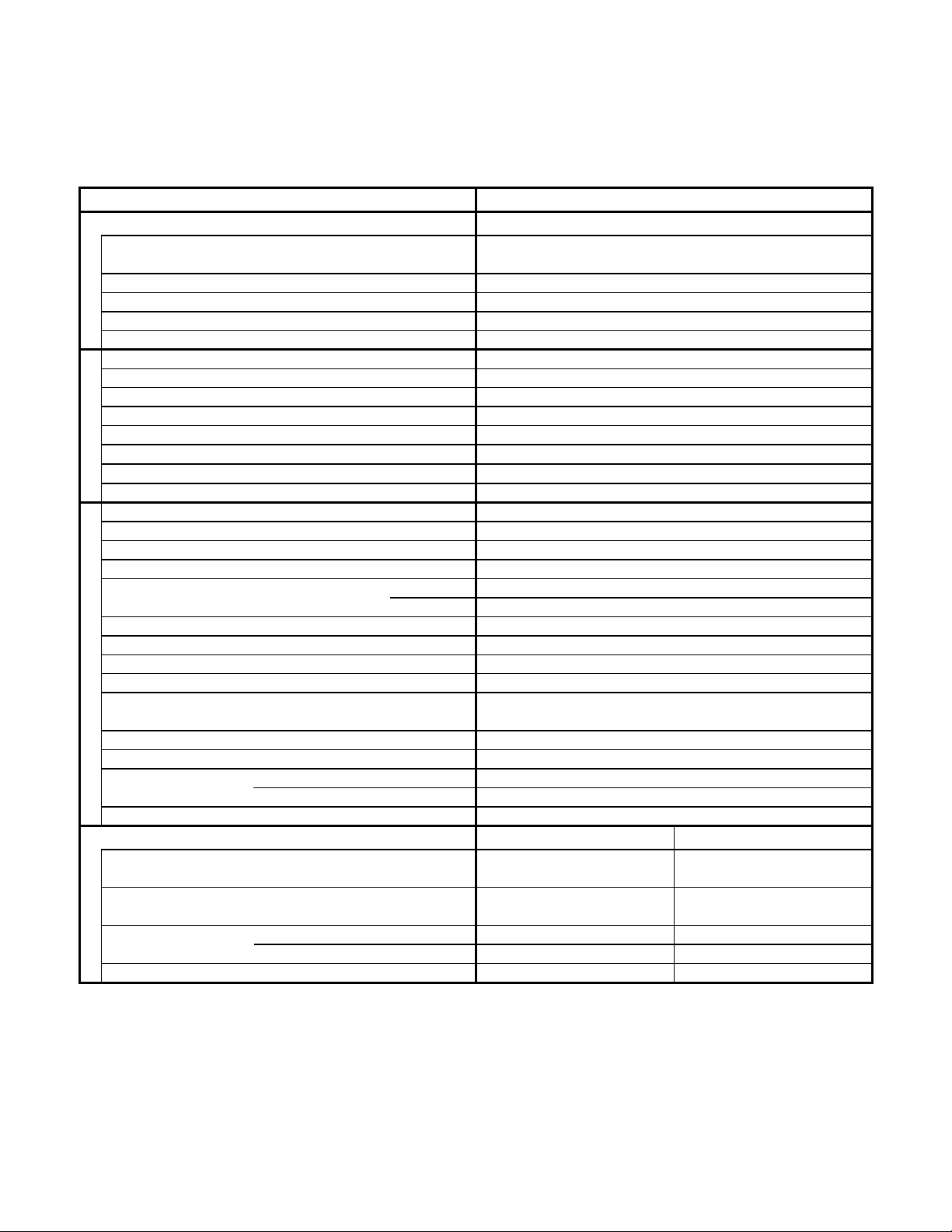
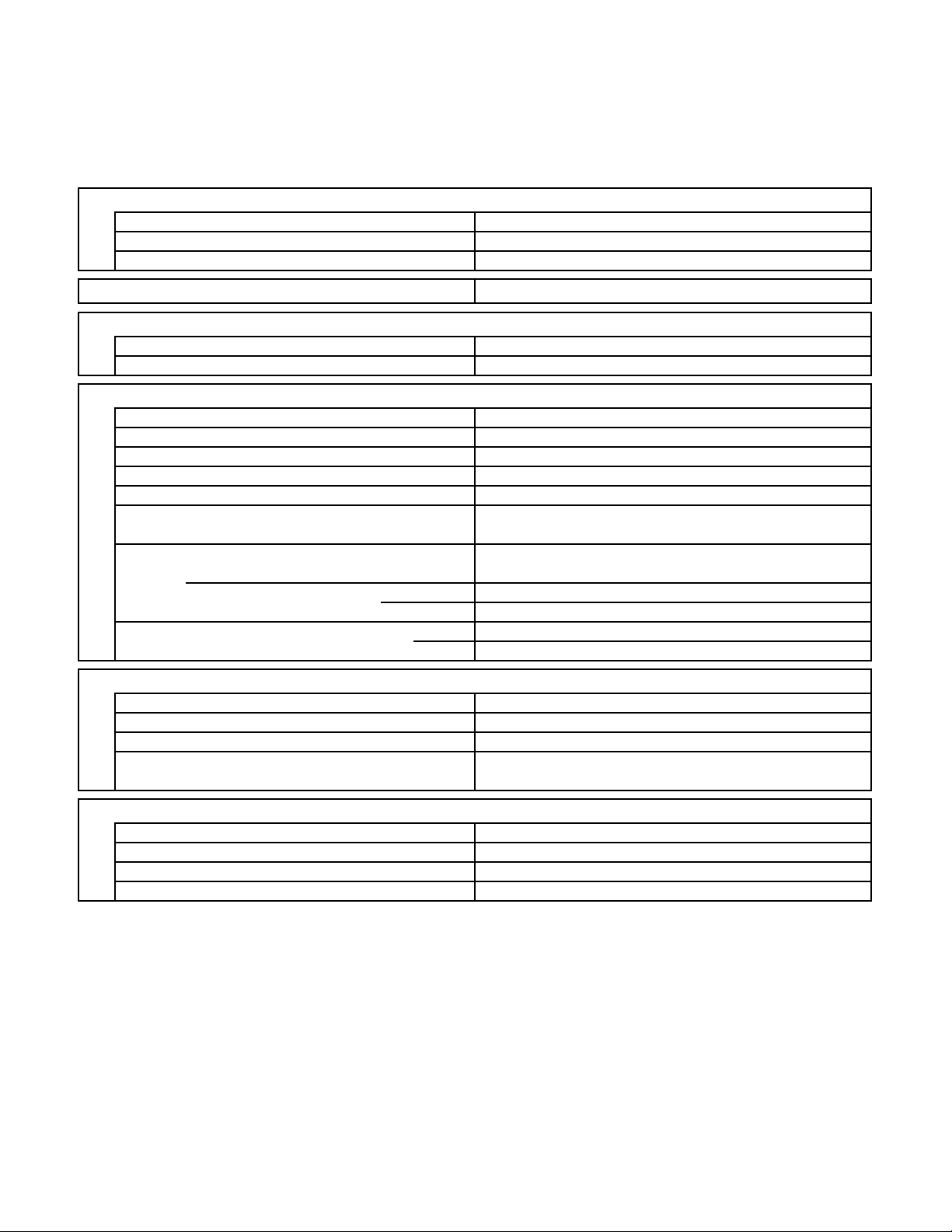
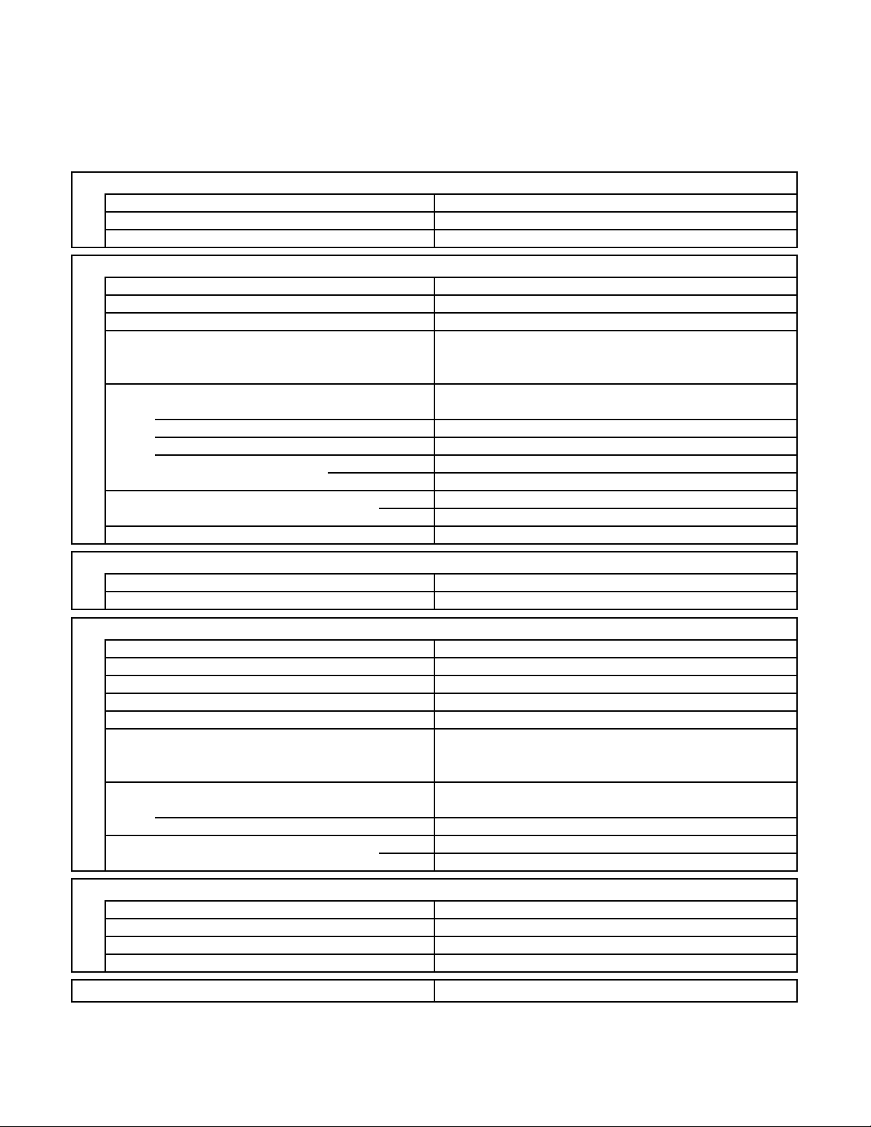
2-3. Other Component Specifications
Indoor Unit KS0971
KS1271
Outdoor Unit C0971 C1271
CL0971 CL1271
Indoor air temp sensor
(Model:PTM-D51H-S3 TH2)
Indoor heat exchanger sensor
(Model:PTM-D51H-S3 TH1)
Compressor temp sensor
(Model:DTN-TKS274Y TH2)
10
9
8
7
6
5
Resistance (k ohm)
4
3
2
1
0
50
59 68 77 86 95 104
(10) (15) (20) (25) (30) (35) (40)
Temperature °F (°C)
200
180
160
140
120
100
Resistance (k ohm)
80
60
40
20
0
32 50 68 86 104 122 140 158 176 194
(0) (10) (20) (30) (40)(50) (60) (70)(80) (90)
Temperature °F (°C)
Outdoor air temp sensor
(Model:DTN-TKS269B)
Outdoor heat exchanger sensor
(Model:DTN-TKS274Y TH1)
40
35
30
25
20
Resistance (k ohm)
15
10
5
0
-
4514 23 32 41 50 59 68
(
-
20)(-15)(-10) (-5) (0) (5) (10) (15) (20)
16
Temperature °F (°C)
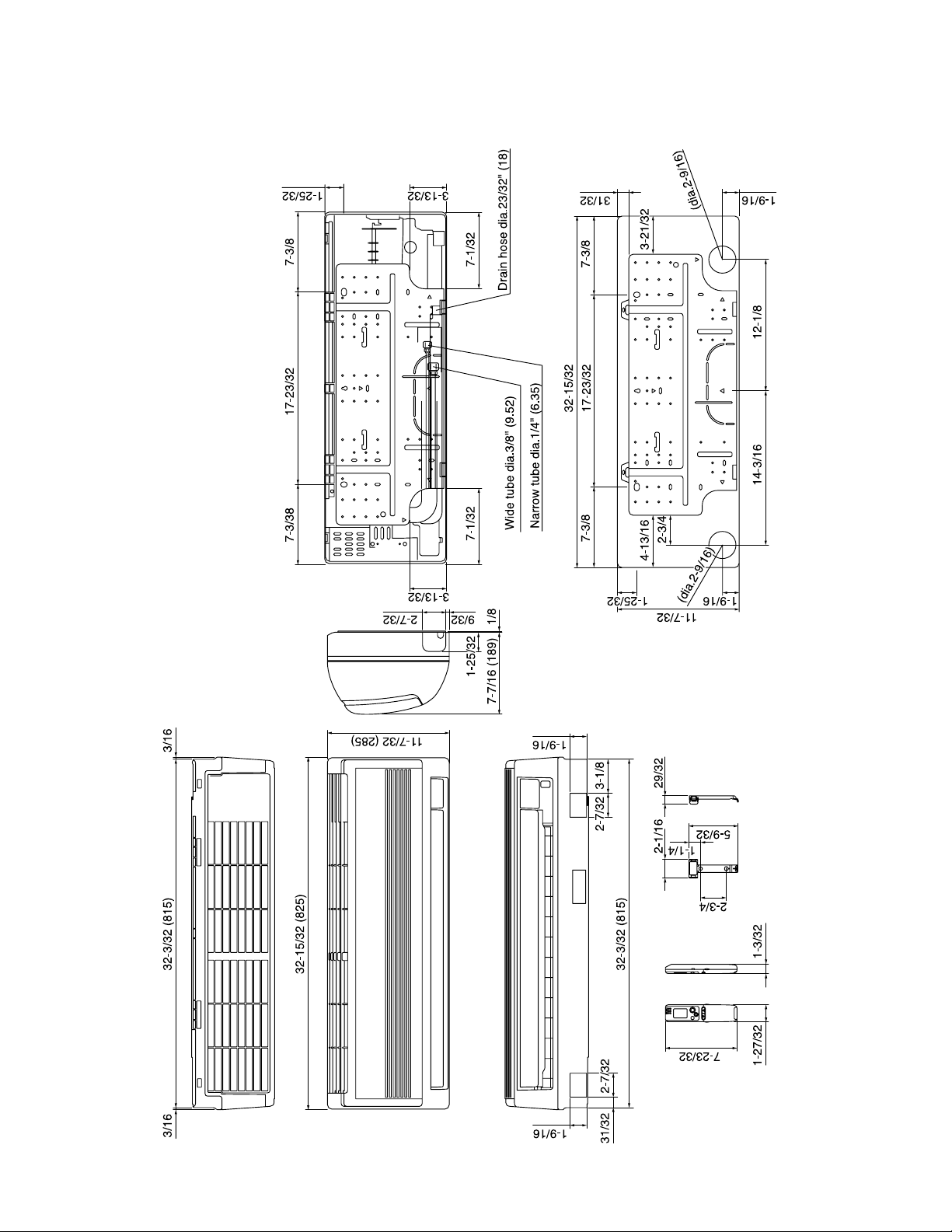
3. DIMENSIONAL DATA
Indoor Unit KS0971
KS1271
17
Unit: inch(mm)
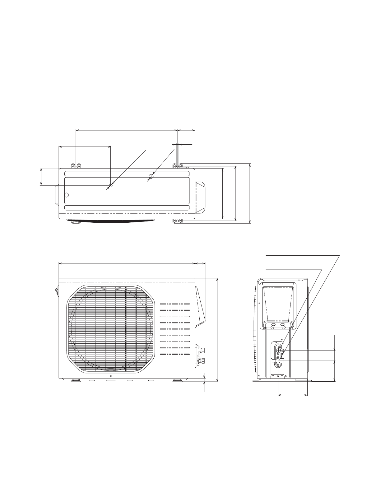
Outdoor Unit C0971 C1271
CL0971 CL1271
3-19/32
10-13/16
21-3/16
ID:23/32
28-11/32 (720) 2-1/8
2-ID:15/16
3-19/32
15/32
11-13/32
10-7/16(265)
12-7/16
Wide tube service valve
dia.3/8" (9.52)
Narrow tube service valve
dia.1/4" (6.35)
18
5/8
21-9/16 (548)
4-9/32 2-5/32
6-3/32
Unit: inch(mm)
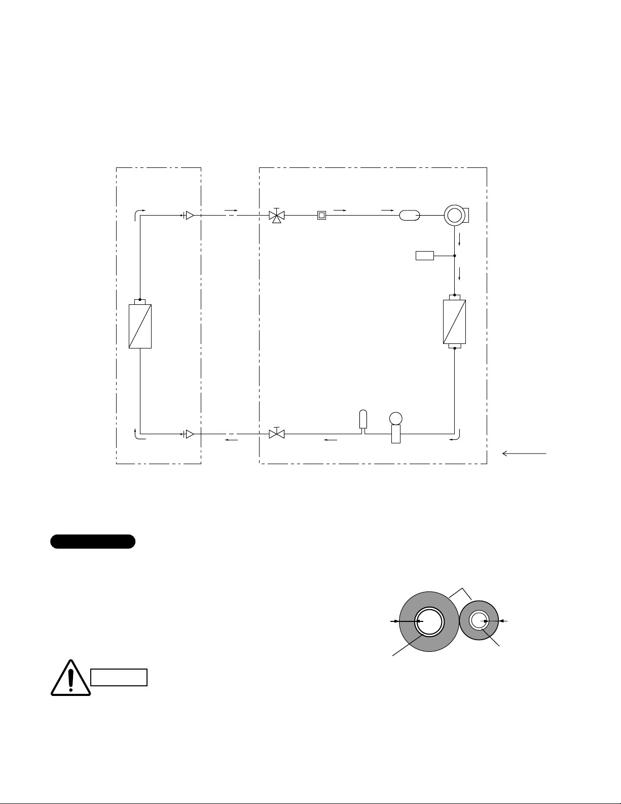
4. REFRIGERANT FLOW DIAGRAM
4-1. Refrigerant Flow Diagram
Indoor Unit KS0971
KS1271
Indoor unit Outdoor unit
Heat exchanger
Narrow tube
Wide tube
O.D.
3/8"
(9.52 mm)
Outdoor Unit C0971 C1271
CL0971 CL1271
Wide tube
service
valve
Muffler
Narrow
tube
service
valve
Accumulator
Electric
expansion
valve
M
High pressure
switch
H.P.
Compressor
Heat exchanger
O.D.
1/4"
(6.35 mm)
Insulation of Refrigerant Tubing
IMPORTANT
Because capillary tubing is used in the outdoor unit, both the
wide and narrow tubes of this air conditioner become cold. To
prevent heat loss and wet floors due to dripping of
condensation, both tubes must be well insulated with a
proper insulation material. The thickness of the insulation
should be a min. 5/16"(8 mm).
After a tube has been insulated,
CAUTION
never try to bend it into a narrow
curve because it can cause the tube
to break or crack.
Muffler
*1
*1: 0nly for C1271/CL1271
Thickness:
Min. 5/16"(8 mm)
Wide tube
Cooling cycle
Insulation
Thickness:
Min. 5/16"(8 mm)
Narrow tube
19
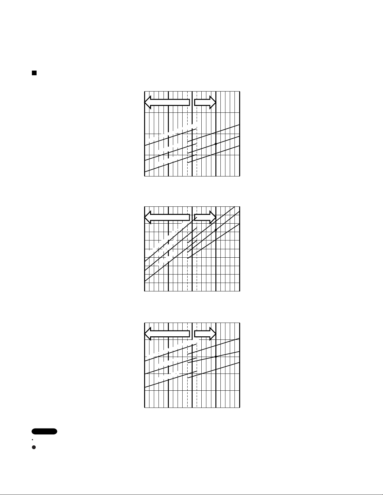
5. PERFORMANCE DATA
5-1. Temperature Charts
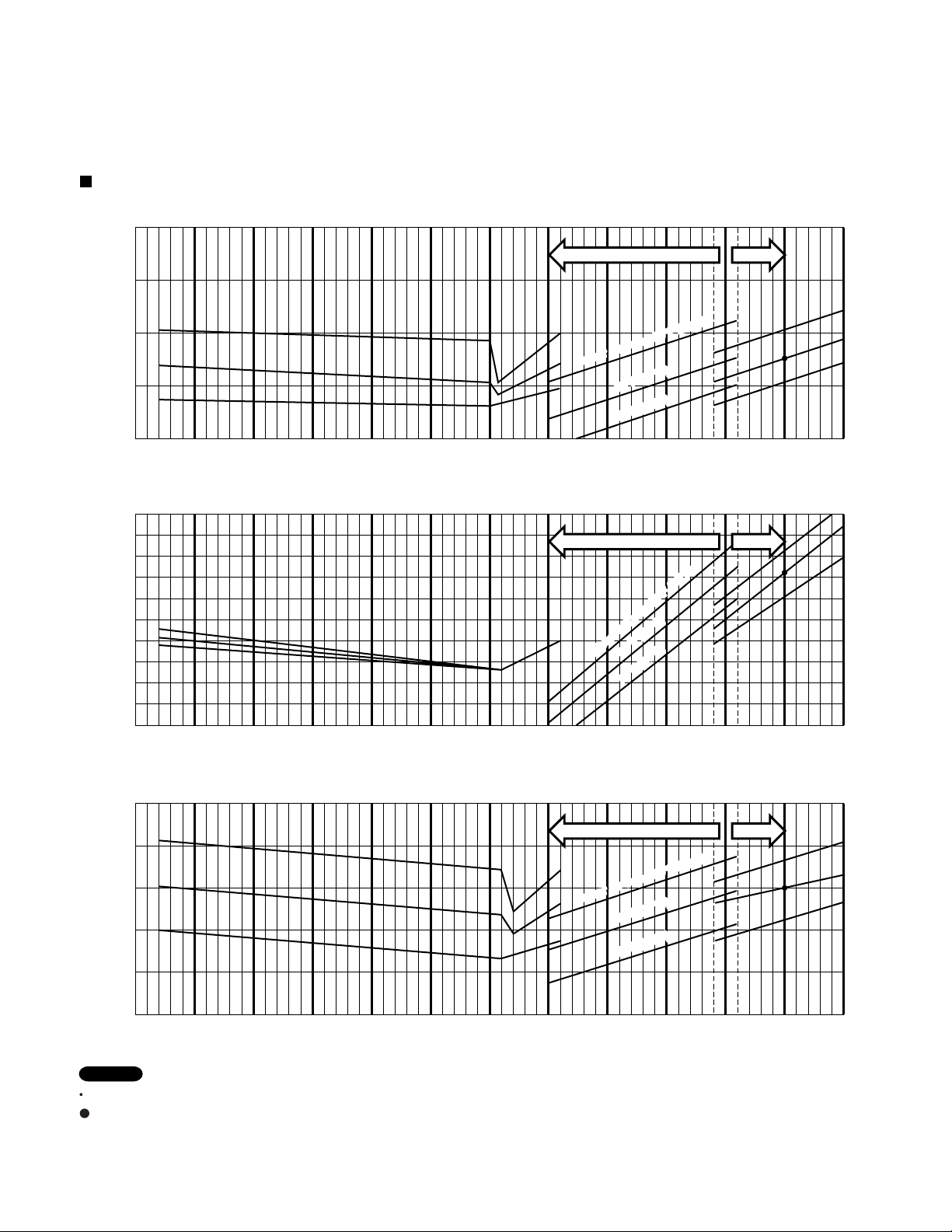
Indoor Unit KS0971 Outdoor Unit C0971
Cooling Characteristics (RH : 46%, Indoor fan speed : High fan) (60Hz, 115V)
(1) Low pressure performance chart
173
(1.2)
Hi FanLo fan
159
(1.1)
psig(MPaG)
C)
°
30
F (
F (
77
(25)
°
C)
°
°C)
27
27
C)
°C)
°
24
24
86
(30)
95
(35)
104
(40)
145
(1.0)
131
(0.9)
117
Low pressure at wide tube service valve
(0.8)
(2) Operating current performance chart
Indoor Air Temp.86
Indoor Air Temp.86°F (30°C)
°F (
°F (
80
80
°F (
°
75
75
68
(20)
Outdoor inlet air D.B. temp.°F(°C)
9
8
7
6
Operating current (A)
5
4
68
(20)
(3) Indoor discharge air performance chart
64.4 (18)
°C)
60.8 (16)
57.2 (14)
53.6 (12)
50.0 (10)
Hi FanLo fan
C)
°
F (30
°
°C)
°C)
27
27
°F (
°F (
C)
80
80
Indoor Air Temp.86
Indoor Air Temp.86°F (30°C)
°
°C)
24
24
F (
°
°F (
75
75
77
(25)
86
(30)
Outdoor inlet air D.B. temp.°F(°C)
Hi FanLo fan
)
°C)
30
F (
°
Indoor Air Temp.86
Indoor Air Temp.86°F (30°C
80
80
75°
75
F (
°
°F (
F (
°F (
C)
°
°C)
27
27
C)
°C)
°
24
24
95
(35)
104
(40)
Indoor discharge air temperature °F(
46.4 (8)
68
(20)
77
(25)
86
(30)
95
(35)
104
(40)
Outdoor inlet air D.B. temp.°F(°C)
NOTE
Check each performance value in test-run mode. Electrical performance values represent a combined indoor/outdoor value.
:Points of rating condition
Black dots in above charts indicate the following rating conditions.
Cooling: Indoor air temperature 80 °F D.B. / 67 °F W.B. Outdoor air temperature 95 °F D.B.
20
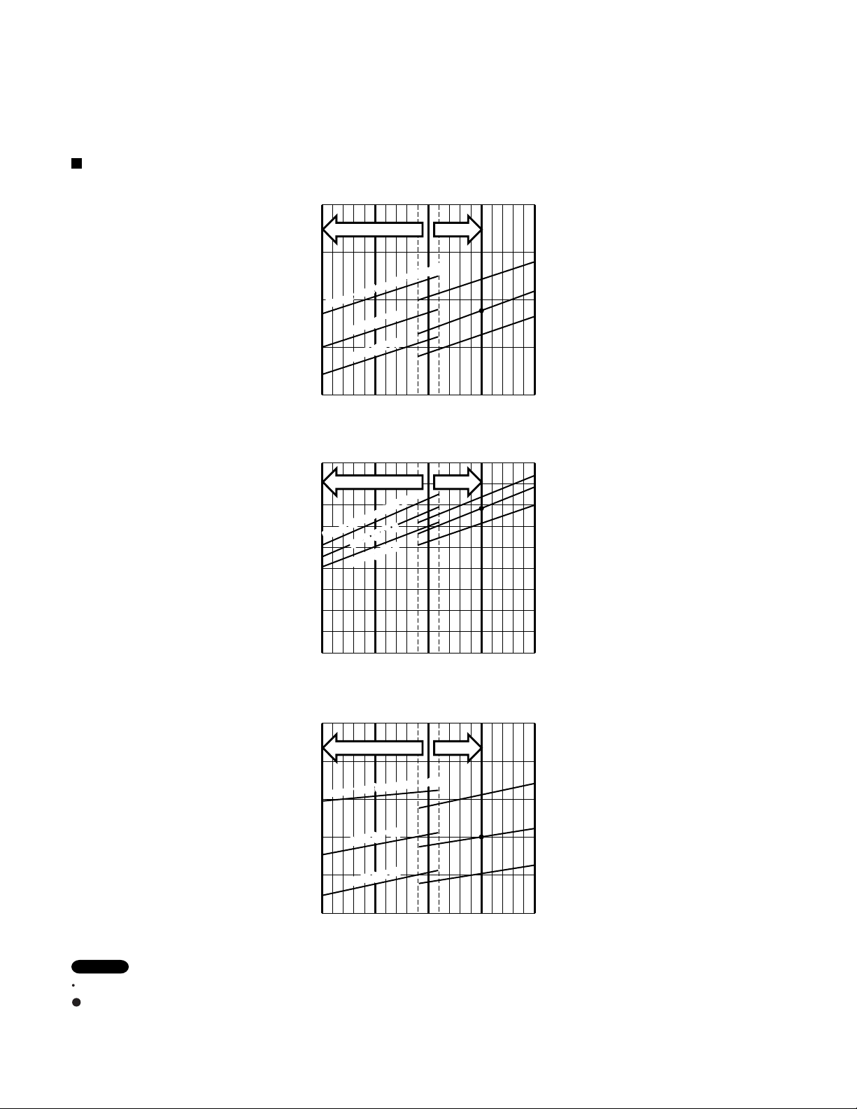
Indoor Unit KS0971 Outdoor Unit CL0971
Cooling Characteristics (RH : 46%, Indoor fan speed : High fan) (60Hz, 115V)
(1) Low pressure performance chart
173
(1.2)
159
(1.1)
psig(MPaG)
145
(1.0)
Indoor Air Temp.86
Indoor Air Temp.86°F (30°C)
131
(0.9)
117
Low pressure at wide tube service valve
(0.8)
-4
(-20)
5
(-15)
14
(-10)
23
(-5)
(2) Operating current performance chart
9
32
(0)
41
(5)
50
(10)
Outdoor inlet air D.B. temp.°F(°C)
59
(15)
68
(20)
°F (
°F (
80
80
F (
°F (
°
75
75
Hi FanLo fan
C)
°
30
F (
°
°C)
°C)
27
27
C)
°C)
°
24
24
77
(25)
86
(30)
95
(35)
104
(40)
8
7
6
Operating current (A)
5
4
-4
(-20)
5
(-15)
14
(-10)
23
(-5)
(3) Indoor discharge air performance chart
64.4 (18)
°C)
60.8 (16)
57.2 (14)
53.6 (12)
50.0 (10)
32
(0)
41
(5)
50
(10)
Outdoor inlet air D.B. temp.°F(°C)
Indoor Air Temp.86
Indoor Air Temp.86°F (30°C)
59
(15)
68
(20)
Indoor Air Temp.86
Indoor Air Temp.86°F (30°C)
80
80
75
75
Hi FanLo fan
C)
°
30
F (
°
C)
°
°C)
27
27
°F (
°F (
C)
80
80
°
°C)
24
24
F (
°
°F (
75
75
°
°F (
°F (
°
F (
F (
77
(25)
F (
°
C)
°
°C)
27
27
C)
°C)
°
24
24
86
(30)
C)
°
30
95
(35)
Hi FanLo fan
104
(40)
Indoor discharge air temperature °F(
46.4 (8)
-4
(-20)
5
(-15)
14
(-10)
23
(-5)
32
(0)
41
(5)
50
(10)
59
(15)
68
(20)
77
(25)
86
(30)
95
(35)
Outdoor inlet air D.B. temp.°F(°C)
NOTE
Check each performance value in test-run mode. Electrical performance values represent a combined indoor/outdoor value.
:Points of rating condition
Black dots in above charts indicate the following rating conditions.
Cooling: Indoor air temperature 80 °F D.B. / 67 °F W.B. Outdoor air temperature 95 °F D.B.
21
104
(40)
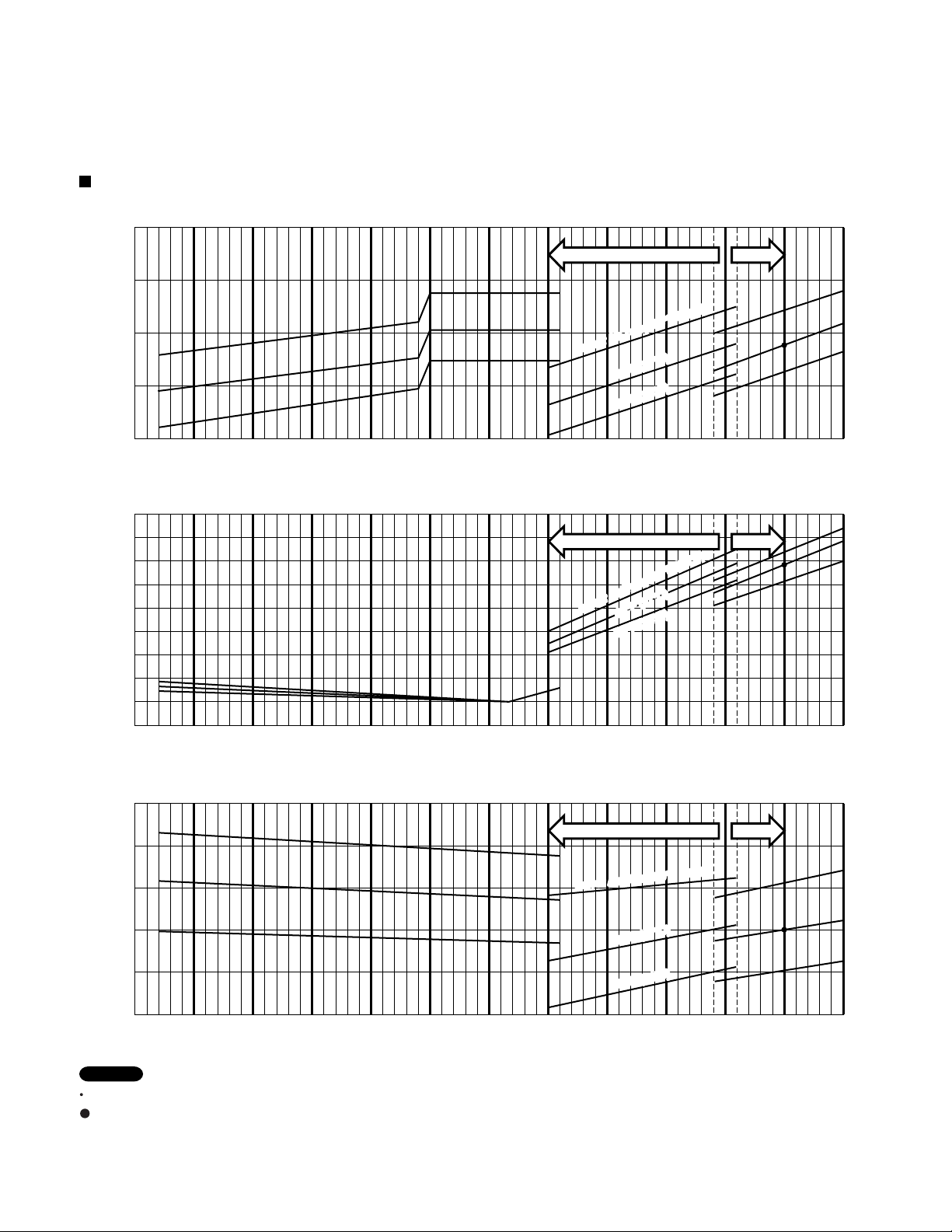
Indoor Unit KS1271 Outdoor Unit C1271
Cooling Characteristics (RH : 46%, Indoor fan speed : High fan) (60Hz, 115V)
(1) Low pressure performance chart
173
(1.2)
Hi FanLo fan
159
(1.1)
psig(MPaG)
145
Indoor Air Temp.86°F (30°C)
(1.0)
131
(0.9)
117
Low pressure at wide tube service valve
(0.8)
(2) Operating current performance chart
Operating current (A)
68
(20)
13
12
11
10
Indoor Air Temp.86°F (30°C)
9
8
7
6
5
4
68
(20)
°C)
27
°F (
80
°C)
24
°F (
75
77
(25)
86
(30)
95
(35)
Outdoor inlet air D.B. temp.°F(°C)
Hi FanLo fan
°C)
27
°F (
80
°C)
24
°F (
75
77
(25)
86
(30)
95
(35)
Outdoor inlet air D.B. temp.°F(°C)
104
(40)
104
(40)
(3) Indoor discharge air performance chart
64.4 (18)
°C)
86
(30)
Hi FanLo fan
95
(35)
104
(40)
60.8 (16)
57.2 (14)
53.6 (12)
50.0 (10)
Indoor discharge air temperature °F(
46.4 (8)
Indoor Air Temp.86°F (30°C)
°C)
27
°F (
80
°C)
24
°F (
75
68
(20)
77
(25)
Outdoor inlet air D.B. temp.°F(°C)
NOTE
Check each performance value in test-run mode. Electrical performance values represent a combined indoor/outdoor value.
:Points of rating condition
Black dots in above charts indicate the following rating conditions.
Cooling: Indoor air temperature 80 °F D.B. / 67 °F W.B. Outdoor air temperature 95 °F D.B.
22
Indoor Unit KS1271 Outdoor Unit CL1271
Cooling Characteristics (RH : 46%, Indoor fan speed : High fan) (60Hz, 115V)
(1) Low pressure performance chart
173
(1.2)
159
(1.1)
psig(MPaG)
145
(1.0)
131
(0.9)
117
Low pressure at wide tube service valve
(0.8)
-4
(-20)
5
(-15)
14
(-10)
23
(-5)
(2) Operating current performance chart
13
12
11
10
9
8
7
Operating current (A)
6
5
4
-4
(-20)
5
(-15)
14
(-10)
23
(-5)
(0)
32
41
(5)
50
(10)
Outdoor inlet air D.B. temp.°F(°C)
(0)
32
41
(5)
50
(10)
Outdoor inlet air D.B. temp.°F(°C)
Indoor Air Temp.86°F (30°C)
80
75
59
(15)
59
(15)
68
(20)
Indoor Air Temp.86°F (30°C)
80
75
68
(20)
°F (
°F (
°F (
°F (
Hi FanLo fan
°C)
27
°C)
24
77
(25)
°C)
27
°C)
24
77
(25)
86
(30)
86
(30)
95
(35)
Hi FanLo fan
95
(35)
104
(40)
104
(40)
(3) Indoor discharge air performance chart
64.4 (18)
°C)
86
(30)
Hi FanLo fan
95
(35)
60.8 (16)
57.2 (14)
53.6 (12)
50.0 (10)
Indoor discharge air temperature °F(
46.4 (8)
-4
(-20)
5
(-15)
14
(-10)
23
(-5)
(0)
Indoor Air Temp.86°F (30°C)
°C)
27
°F (
80
°C)
24
°F (
75
32
41
(5)
50
(10)
59
(15)
68
(20)
77
(25)
Outdoor inlet air D.B. temp.°F(°C)
NOTE
Check each performance value in test-run mode. Electrical performance values represent a combined indoor/outdoor value.
:Points of rating condition
Black dots in above charts indicate the following rating conditions.
Cooling: Indoor air temperature 80 °F D.B. / 67 °F W.B. Outdoor air temperature 95 °F D.B.
23
104
(40)
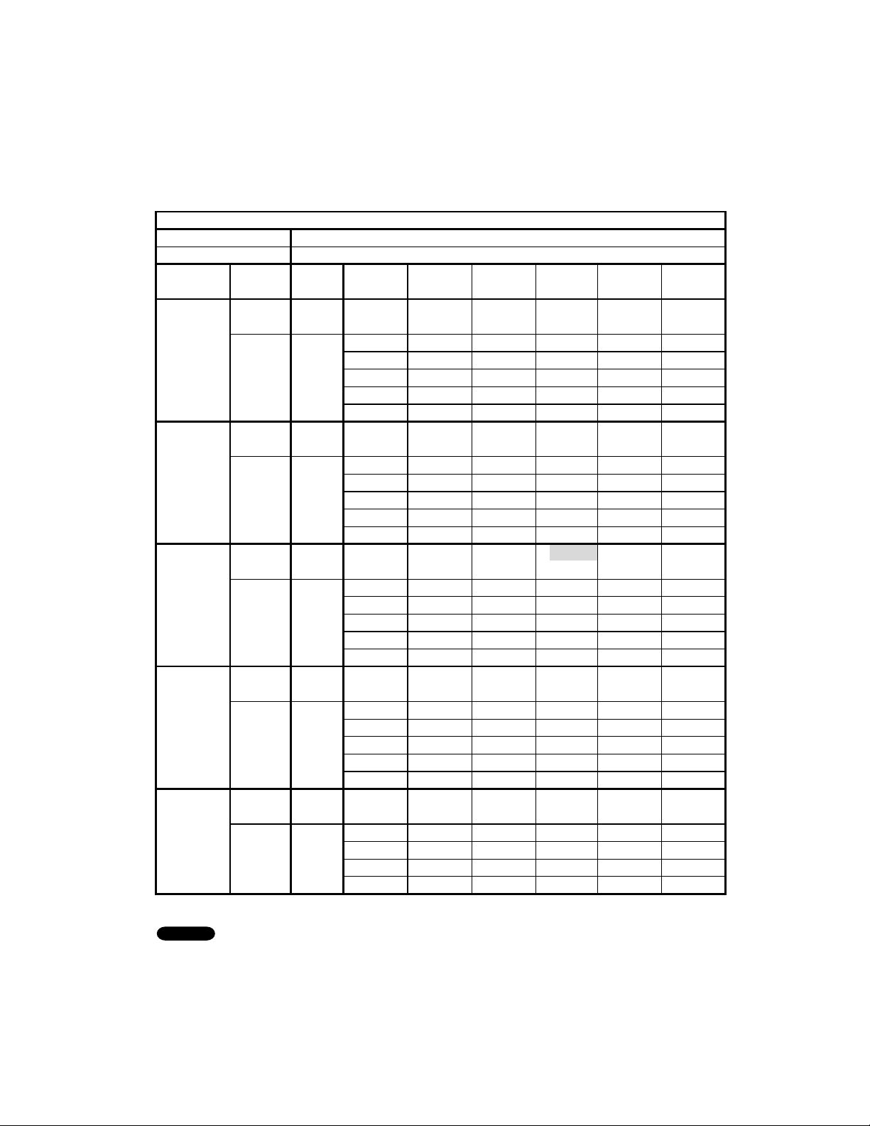
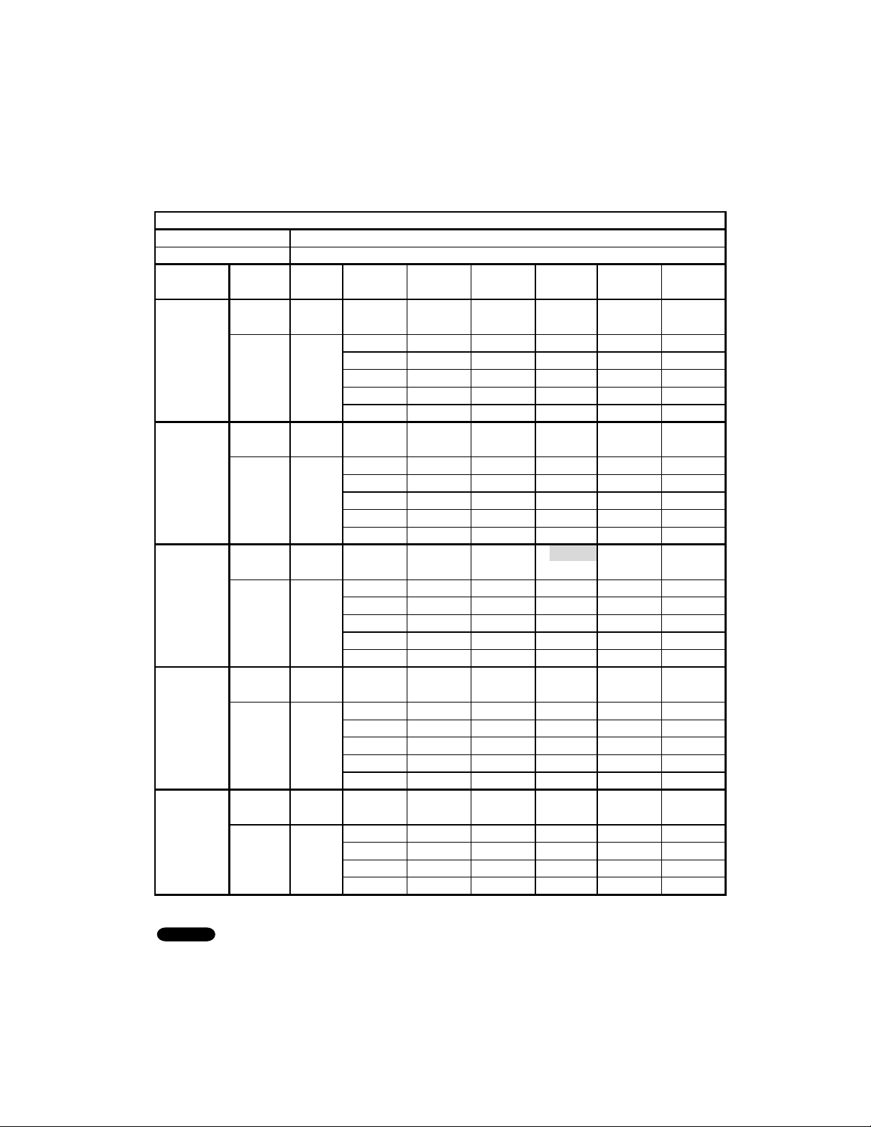
5-2. Cooling Capacity
Indoor Unit : KS0971
Outdoor Unit : C0971 / CL0971
Power Supply : 115V Single Phase 60Hz
< Cooling Capacity >
RATING CAPACITY: 9,000 BTU/h AIR FLOW RATE: 282 CFM
INDOOR OUTDOOR
ENT. TEMP. oF (oC) AMBIENT TEMP. oF (oC)
W.B. D.B. 65 75 85 95 105 115
TC 9,080 8,800 8,500 8,260 7,890 6,400
72 (22.2) SHC 6,870 6,760 6,590 6,480 6,320 5,610
59 76 (24.4) SHC 7,860 7,690 7,580 7,470 7,250 6,400
(15.0) 80 (26.7) SHC 8,840 8,730 8,500 8,260 7,890 6,400
84 (28.9) SHC 9,080 8,800 8,500 8,260 7,890 6,400
88 (31.1) SHC 9,080 8,800 8,500 8,260 7,890 6,400
TC 9,440 9,160 8,860 8,630 8,250 6,580
72 (22.2) SHC 5,770 5,610 5,500 5,390 5,220 4,510
63 76 (24.4) SHC 6,700 6,590 6,430 6,370 6,160 5,500
(17.2) 80 (26.7) SHC 7,690 7,580 7,470 7,360 7,200 6,480
84 (28.9) SHC 8,680 8,570 8,400 8,300 8,130 6,580
88 (31.1) SHC 9,440 9,160 8,860 8,630 8,250 6,580
TC 9,790 9,520 9,220 # 9,000 8,620 6,740
(18.3) (23.9) (29.4) (35.0) (40.6) (46.1)
72 (22.2) SHC 4,620 4,450 4,350 4,290 4,130 3,410
67 76 (24.4) SHC 5,550 5,440 5,330 5,220 5,060 4,350
(19.4) 80 (26.7) SHC 6,540 6,430 6,320 6,210 6,100 5,330
84 (28.9) SHC 7,530 7,420 7,310 7,200 7,030 6,320
88 (31.1) SHC 8,460 8,350 8,240 8,190 8,020 6,740
TC 10,120 9,860 9,560 9,360 8,980 6,890
72 (22.2) SHC 3,360 3,250 3,140 3,080 2,920 2,210
71 76 (24.4) SHC 4,350 4,240 4,130 4,020 3,910 3,190
(21.7) 80 (26.7) SHC 5,330 5,220 5,110 5,060 4,890 4,180
84 (28.9) SHC 6,270 6,210 6,100 5,990 5,880 5,110
88 (31.1) SHC 7,250 7,140 7,030 6,980 6,810 6,100
TC 10,400 10,140 9,840 9,680 9,300 7,010
75 76 (24.4) SHC 3,140 3,030 2,920 2,860 2,750 2,040
(23.9) 80 (26.7) SHC 4,130 4,070 3,960 3,910 3,800 3,030
84 (28.9) SHC 5,110 5,000 4,890 4,840 4,730 4,020
88 (31.1) SHC 6,050 5,990 5,880 5,830 5,720 4,950
TC : Total Cooling Capacity (BTU/h) SHC : Sensible Heat Capacity (BTU/h)
NOTE
1.
Rating conditions (#)
: Indoor Unit Entering Air Temp. 80 °F (26.7 °C) D.B. / 67 °F (19.4 °C) W.B.
: Outdoor Ambient Temp. 95 °F (35 °C) D.B.
2.
Above data does not take Freeze Prevention Protection during cooling operation into account.
For this reason, the value may vary from the actual cooling characteristics.
3. Above data represents the value when the operation frequency of a compressor is fixed.
24
Indoor Unit : KS1271
Outdoor Unit : C1271 / CL1271
Power Supply : 115V Single Phase 60Hz
< Cooling Capacity >
RATING CAPACITY: 11,900 BTU/h AIR FLOW RATE: 294 CFM
INDOOR OUTDOOR
ENT. TEMP. oF (oC) AMBIENT TEMP. oF (oC)
W.B. D.B. 65 75 85 95 105 115
TC 11,970 11,660 11,310 11,050 10,620 8,860
72 (22.2) SHC 8,480 8,300 8,130 7,960 7,730 6,880
59 76 (24.4) SHC 9,450 9,280 9,100 8,990 8,760 7,850
(15.0) 80 (26.7) SHC 10,530 10,360 10,130 10,020 9,790 8,860
84 (28.9) SHC 11,500 11,330 11,160 10,990 10,620 8,860
88 (31.1) SHC 11,970 11,660 11,310 11,050 10,620 8,860
TC 12,370 12,070 11,730 11,480 11,050 9,020
72 (22.2) SHC 7,220 7,050 6,880 6,760 6,530 5,620
63 76 (24.4) SHC 8,190 8,020 7,850 7,730 7,560 6,590
(17.2) 80 (26.7) SHC 9,220 9,100 8,930 8,820 8,590 7,680
84 (28.9) SHC 10,250 10,080 9,900 9,790 9,560 8,650
88 (31.1) SHC 11,220 11,050 10,880 10,760 10,590 9,020
TC 12,740 12,450 12,120 # 11,900 11,470 9,160
(18.3) (23.9) (29.4) (35.0) (40.6) (46.1)
72 (22.2) SHC 5,900 5,730 5,620 5,500 5,330 4,360
67 76 (24.4) SHC 6,880 6,760 6,590 6,530 6,300 5,330
(19.4) 80 (26.7) SHC 7,900 7,790 7,620 7,560 7,330 6,420
84 (28.9) SHC 8,930 8,760 8,650 8,530 8,360 7,390
88 (31.1) SHC 9,900 9,790 9,620 9,560 9,330 8,360
TC 13,080 12,800 12,470 12,290 11,870 9,270
72 (22.2) SHC 4,480 4,360 4,250 4,190 4,020 3,050
71 76 (24.4) SHC 5,500 5,390 5,220 5,160 4,990 4,020
(21.7) 80 (26.7) SHC 6,530 6,420 6,300 6,190 6,080 5,050
84 (28.9) SHC 7,500 7,390 7,280 7,220 7,050 6,080
88 (31.1) SHC 8,530 8,420 8,300 8,190 8,020 7,050
TC 13,320 13,060 12,750 12,610 12,210 9,330
75 76 (24.4) SHC 4,130 4,020 3,960 3,900 3,730 2,760
(23.9) 80 (26.7) SHC 5,160 5,100 4,990 4,930 4,760 3,790
84 (28.9) SHC 6,190 6,080 5,960 5,900 5,790 4,820
88 (31.1) SHC 7,160 7,100 6,990 6,930 6,760 5,790
TC : Total Cooling Capacity (BTU/h) SHC : Sensible Heat Capacity (BTU/h)
NOTE
1.
Rating conditions (#)
: Indoor Unit Entering Air Temp. 80 °F (26.7 °C) D.B. / 67 °F (19.4 °C) W.B.
: Outdoor Ambient Temp. 95 °F (35 °C) D.B.
2.
Above data does not take Freeze Prevention Protection during cooling operation into account.
For this reason, the value may vary from the actual cooling characteristics.
3. Above data represents the value when the operation frequency of a compressor is fixed.
25
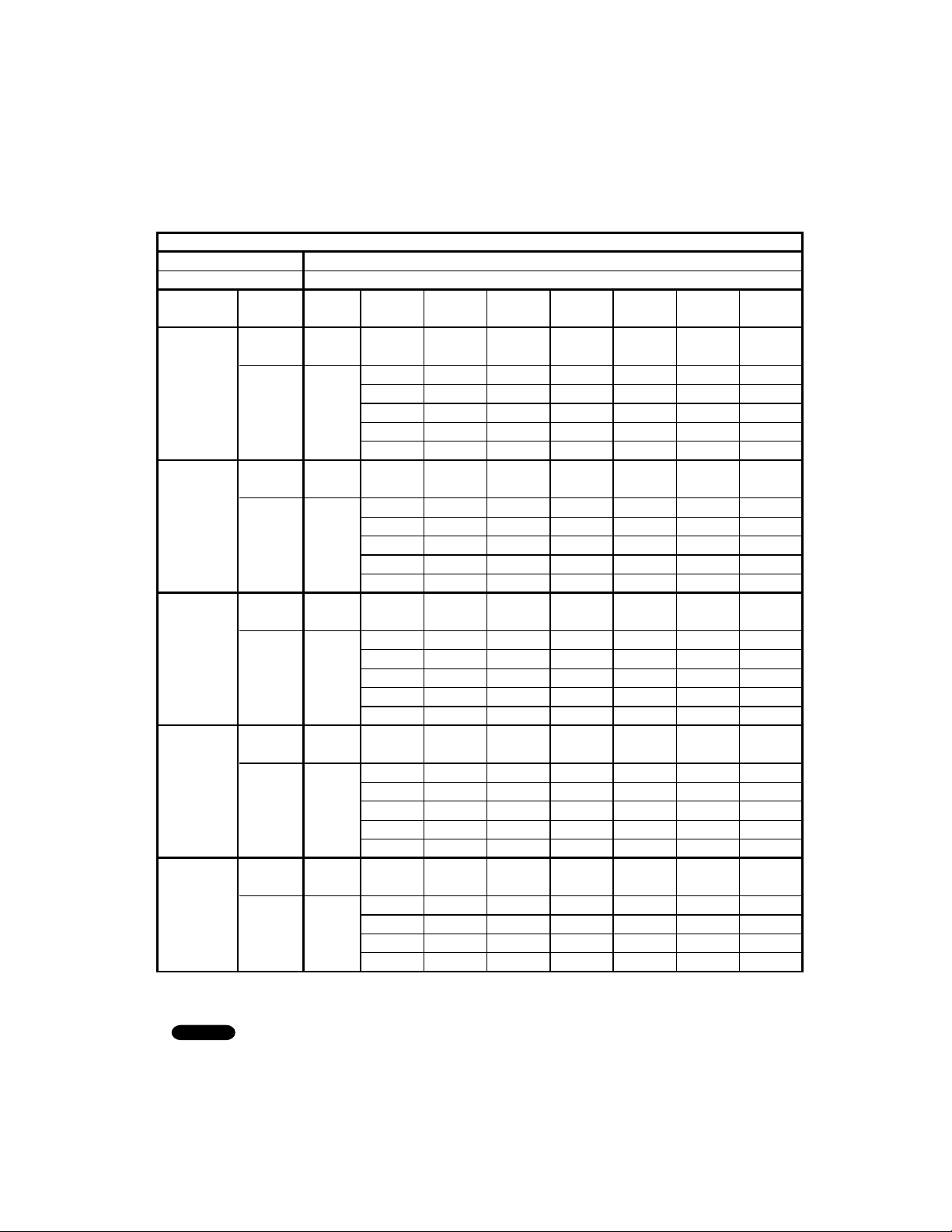
5-3. Cooling Capacity (Low Ambient)
Indoor Unit : KS0971
Outdoor Unit : CL0971
Power Supply : 115V Single Phase 60Hz
< Cooling Capacity (Low Ambient) >
RATING CAPACITY: 9,000 BTU/h AIR FLOW RATE: 282 CFM
INDOOR OUTDOOR
ENT. TEMP.
W.B. D.B. 0515 25 35 45 55
59 76 (24.4) SHC 8,190 8,240 8,190 8,240 8,240 8,240 8,190
(15.0) 80 (26.7) SHC 9,230 9,230 9,230 9,230 9,230 9,230 9,230
63 76 (24.4) SHC 6,810 6,810 6,870 6,920 6,980 6,980 6,980
(17.2) 80 (26.7) SHC 7,800 7,860 7,860 7,910 7,970 7,970 7,970
o
F (oC) AMBIENT TEMP. oF (oC)
(-17.8) (-15.0) (-9.4) (-3.9) (1.7) (7.2) (12.8)
TC 9,770 9,790 9,760 9,800 9,840 9,850 9,780
72 (22.2) SHC 7,250 7,250 7,250 7,250 7,250 7,310 7,250
84 (28.9) SHC 9,770 9,790 9,760 9,800 9,840 9,850 9,780
88 (31.1) SHC 9,770 9,790 9,760 9,800 9,840 9,850 9,780
TC 9,670 9,700 9,760 9,860 9,960 10,010 9,980
72 (22.2) SHC 5,880 5,880 5,880 5,940 5,990 5,990 5,990
84 (28.9) SHC 8,790 8,790 8,840 8,900 8,900 8,950 8,950
88 (31.1) SHC 9,670 9,700 9,760 9,830 9,890 9,890 9,890
TC 9,460 9,510 9,660 9,840 10,010 10,120 10,120
72 (22.2) SHC 4,450 4,450 4,560 4,620 4,670 4,730 4,730
67 76 (24.4) SHC 5,440 5,440 5,500 5,550 5,660 5,720 5,720
(19.4) 80 (26.7) SHC 6,430 6,430 6,480 6,590 6,650 6,700 6,700
84 (28.9) SHC 7,360 7,420 7,470 7,530 7,640 7,640 7,640
88 (31.1) SHC 8,350 8,350 8,400 8,510 8,570 8,620 8,620
TC 9,100 9,170 9,440 9,730 9,980 10,160 10,210
72 (22.2) SHC 2,970 3,030 3,080 3,190 3,300 3,360 3,410
71 76 (24.4) SHC 3,960 3,960 4,070 4,180 4,290 4,350 4,350
(21.7) 80 (26.7) SHC 4,950 5,000 5,060 5,170 5,280 5,330 5,390
84 (28.9) SHC 5,940 5,940 6,050 6,160 6,210 6,320 6,320
88 (31.1) SHC 6,870 6,920 6,980 7,090 7,200 7,250 7,310
TC 8,630 8,720 9,130 9,530 9,880 10,120 10,220
75 76 (24.4) SHC 2,530 2,590 2,700 2,860 2,970 3,030 3,080
(23.9) 80 (26.7) SHC 3,580 3,580 3,740 3,850 3,960 4,020 4,070
84 (28.9) SHC 4,510 4,560 4,670 4,780 4,950 5,000 5,060
88 (31.1) SHC 5,500 5,500 5,660 5,770 5,880 5,990 5,990
TC : Total Cooling Capacity (BTU/h) SHC : Sensible Heat Capacity (BTU/h)
NOTE
1.
Above data does not take Freeze Prevention Protection during cooling operation into account.
For this reason, the value may vary from the actual cooling characteristics.
2. Above data represents the value when the operation frequency of a compressor is fixed.
26
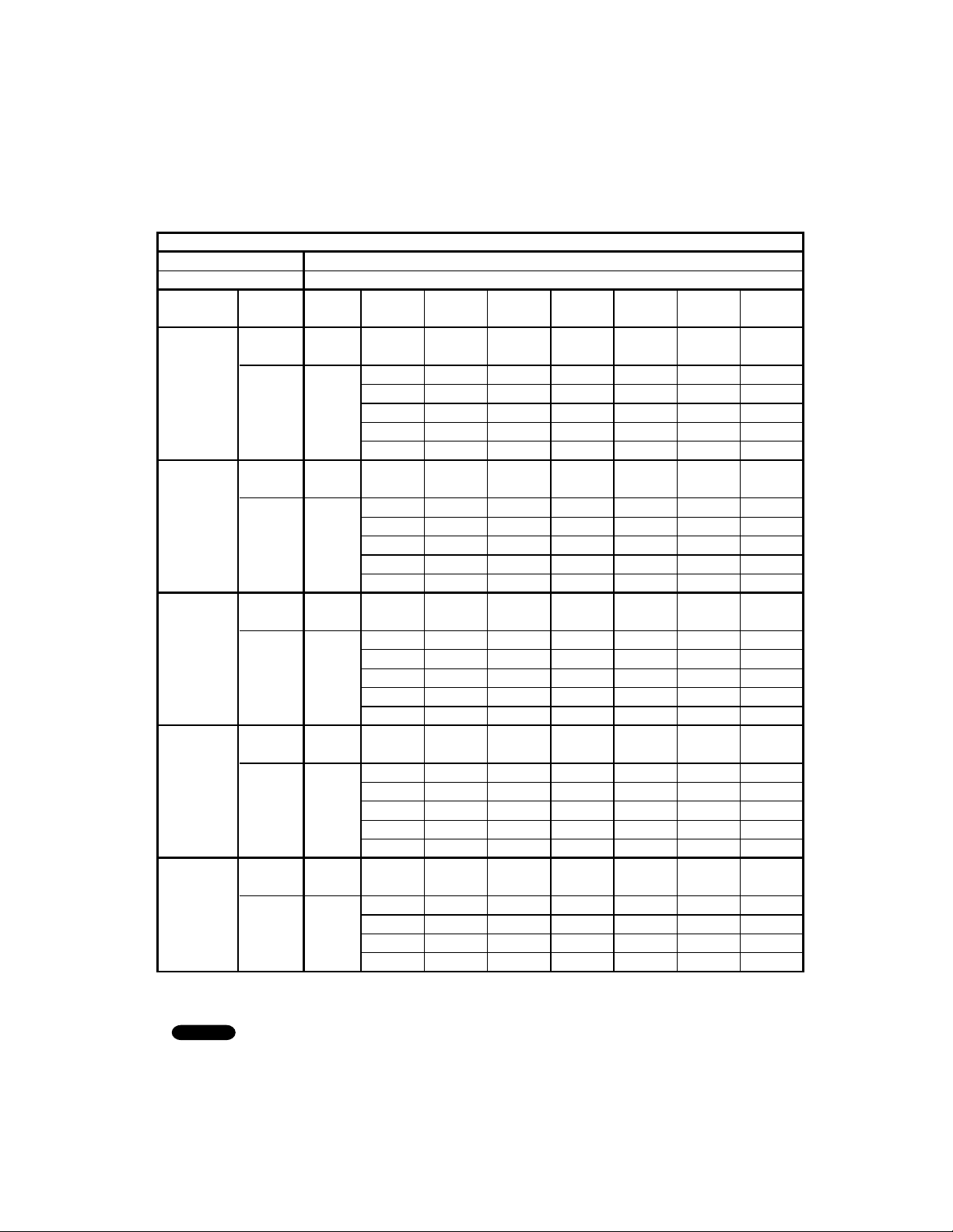
Indoor Unit : KS1271
Outdoor Unit : CL1271
Power Supply : 115V Single Phase 60Hz
< Cooling Capacity (Low Ambient) >
RATING CAPACITY: 11,900 BTU/h AIR FLOW RATE: 294 CFM
INDOOR OUTDOOR
ENT. TEMP.
W.B. D.B. 0515 25 35 45 55
59 76 (24.4) SHC 8,250 8,250 8,250 8,300 8,300 8,300 8,250
(15.0) 80 (26.7) SHC 9,280 9,280 9,330 9,330 9,330 9,330 9,280
63 76 (24.4) SHC 6,880 6,880 6,930 6,930 6,990 6,990 6,990
(17.2) 80 (26.7) SHC 7,900 7,900 7,960 8,020 8,020 8,020 8,020
o
F (oC) AMBIENT TEMP. oF (oC)
TC 9,660 9,670 9,680 9,710 9,730 9,720 9,670
72 (22.2) SHC 7,280 7,280 7,280 7,280 7,280 7,280 7,280
84 (28.9) SHC 9,660 9,670 9,680 9,710 9,730 9,720 9,670
88 (31.1) SHC 9,660 9,670 9,680 9,710 9,730 9,720 9,670
TC 9,610 9,620 9,700 9,780 9,840 9,870 9,840
72 (22.2) SHC 5,900 5,900 5,900 5,960 5,960 6,020 5,960
84 (28.9) SHC 8,930 8,930 8,930 8,990 8,990 9,050 8,990
88 (31.1) SHC 9,610 9,620 9,700 9,780 9,840 9,870 9,840
TC 9,460 9,490 9,640 9,770 9,890 9,960 9,970
(-17.8) (-15.0) (-9.4) (-3.9) (1.7) (7.2) (12.8)
72 (22.2) SHC 4,480 4,480 4,530 4,590 4,650 4,700 4,700
67 76 (24.4) SHC 5,450 5,500 5,560 5,620 5,680 5,680 5,680
(19.4) 80 (26.7) SHC 6,530 6,530 6,590 6,650 6,700 6,700 6,700
84 (28.9) SHC 7,500 7,500 7,560 7,620 7,680 7,730 7,730
88 (31.1) SHC 8,480 8,530 8,590 8,650 8,700 8,700 8,700
TC 9,190 9,240 9,480 9,680 9,860 9,980 10,030
72 (22.2) SHC 2,990 3,050 3,100 3,160 3,280 3,280 3,330
71 76 (24.4) SHC 4,020 4,020 4,130 4,190 4,250 4,300 4,300
(21.7) 80 (26.7) SHC 5,050 5,050 5,160 5,220 5,280 5,330 5,330
84 (28.9) SHC 6,020 6,080 6,130 6,190 6,300 6,300 6,360
88 (31.1) SHC 7,050 7,050 7,160 7,220 7,280 7,330 7,330
TC 8,840 8,900 9,240 9,520 9,760 9,940 10,020
75 76 (24.4) SHC 2,590 2,650 2,760 2,820 2,930 2,990 2,990
(23.9) 80 (26.7) SHC 3,680 3,680 3,790 3,850 3,960 4,020 4,020
84 (28.9) SHC 4,650 4,650 4,760 4,880 4,930 4,990 5,050
88 (31.1) SHC 5,620 5,680 5,790 5,850 5,960 6,020 6,020
TC : Total Cooling Capacity (BTU/h) SHC : Sensible Heat Capacity (BTU/h)
NOTE
1.
Above data does not take Freeze Prevention Protection during cooling operation into account.
For this reason, the value may vary from the actual cooling characteristics.
2. Above data represents the value when the operation frequency of a compressor is fixed.
27
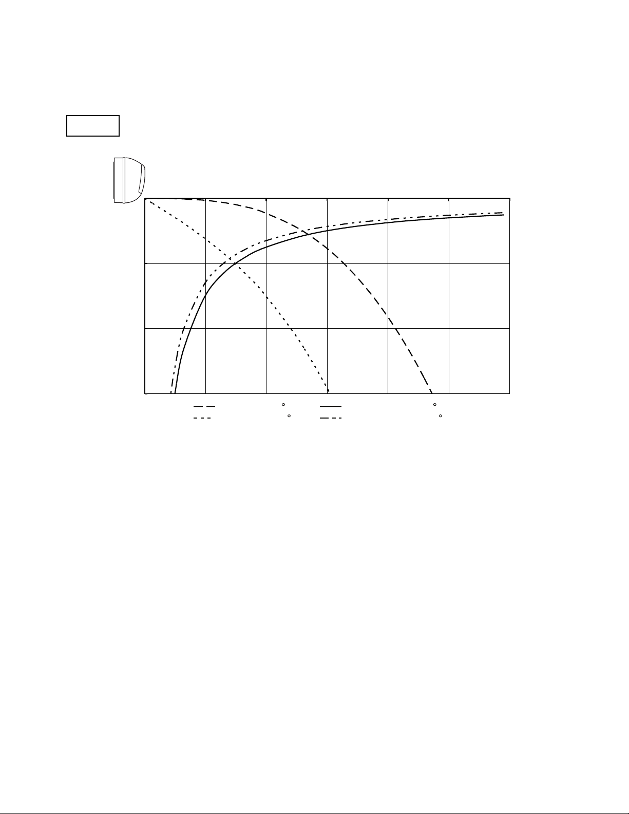
5-4. Air Throw Distance Charts
0
5
10
15
0 5 10 15 20 25 30
Indoor Unit KS0971
Cooling
Room air temp. : 80°F (26.7°C)
Fan speed : High
Axis air velocity (ft./sec.)
Vertical distance (ft.)
Horizontal distance (ft.)
: Flap angle 0 , : Axis air velocity 0
: Flap angle 30 , : Axis air velocity 30
28

Indoor Unit KS1271
0
5
10
15
0 5 10 15 20 25 30
Cooling
Room air temp. :80
Fan speed : High
Axis air velocity (ft./sec.)
Vertical distance (ft.)
(26.7°C)
°F
Horizontal distance (ft.)
: Flap angle 0 , : Axis air velocity 0
: Flap angle 30 , : Axis air velocity 30
29
6. ELECTRICAL DATA
6-1. Electrical Characteristics
Indoor UnitKS0971
C0971
Outdoor Unit
Cooling
Performance at 115V Single-phase 60Hz
Rating conditions Running amp. A 0.45
Rating conditions: Indoor air temperature: 80°F (26.7°C) D.B. / 67°F (19.4°C) W.B.
Outdoor air temperature: 95°F (35°C) D.B.
Indoor Unit KS0971
Outdoor Unit CL0971
Cooling
Performance at 115V Single-phase 60Hz
Rating conditions Running amp. 0.45
Indoor Unit Outdoor Unit Complete Unit
Fan Motor Fan Motor + Compressor
7.15
Power input W
A
Power input 45
W
45
Indoor Unit Outdoor Unit Complete Unit
Fan Motor Fan Motor + Compressor
705
7.15
705
7.6
750
7.6
750
Rating conditions: Indoor air temperature: 80°F (26.7°C) D.B. / 67°F (19.4°C) W.B.
Outdoor air temperature: 95°F (35°C) D.B.
30
 Loading...