


CA21SE1M
Sanyo CA21SE1M, CA21VF1K, CP21VF1K, CP14SE1M, CA21SE1V User Manual
...
CA14SE1M
INSTRUCTION MANUAL
Colour Television
CP14SE1M
CA14SE1K
CP14SE1K
CA14SE1(V)
CP14SE1(V)
CA21CF1(V)
CP21CF1(V)
CA21CF1M
CP21CF1M
CA21SE1M
CP21SE1M
CA21SE1K
CP21SE1K
CA21SE1(V)
CP21SE1(V)
CA21VF1
Multi System
CATV Hyper Band
256 Programmes with Automatic Tuning
CP21VF1
CA21VF1K
CP21VF1K
nings and Cautions
WWararnings and Cautions
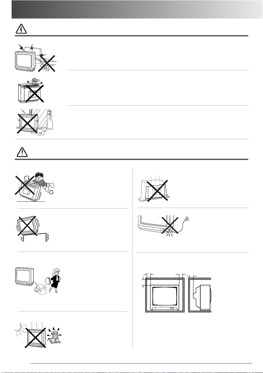
Warning
High voltages are used in the operation of this television receiver. Do not
remove the cabinet back from your set. Refer servicing to qualified service
personnel.
Do not drop or push objects into the television cabinet slots or openings.
Never spill any kind of liquid on the television receiver.
To prevent fire or electrical shock hazard, do not expose the television
receiver to rain or moisture. The television shall not be exposed to dripping
or splashing and that no objects filled with liquids, such as vases, shall be
placed on the television.
Caution
Never stand on, lean on or push suddenly the television or its stand.
You should pay special attention to
children. Serious injury may result if
it should fall.
Do not place your television on an
unstable cart, stand, shelf or table.
Serious injury to an individual, and
damage to the television, may result
if it should fall.
At installation of the unit, the plug
of power cord shall remain
accessible and readily operable
to disconnect the unit from the
wall outlet.
When the television receiver is
not used for an extended period
of time, it is advisable to disconnect the AC power cord from the
AC outlet.
Avoid exposing the television
receiver to direct sunlight and
other source of the heat.
Do not stand the television
receiver directly on other products which give off heat. E.g.
video cassette players, audio
amplifiers.
Minimum distances
10cm
20cm
Heat build-up can reduce the service life of your television, and can also be dangerous.
Do not block the ventilation holes in
the back cover.
Adequate ventilation is essential to
prevent failure of electrical components.
Do not squash power supply
cord under the television
receiver.
10cm
5cm
If the television is to be
built into a
compartment
or similarly
enclosed, the
minimum distances must
be maintained.
2
Contents
Contents
Plug & Play
Plug & Play
Warnings and Cautions . . . . . . . . . . . . . . 2
Contents . . . . . . . . . . . . . . . . . . . . . . . . . 3
Plug & Play . . . . . . . . . . . . . . . . . . . . . . . 3
Front Control . . . . . . . . . . . . . . . . . . . . . 4-5
Remote Control Transmitter . . . . . . . . . . 6
Battery Installation of
the Remote Control Transmitter . . . . . . . 6
General Operation
Remote Control Operation . . . . . . . . . 7
OFF TIMER . . . . . . . . . . . . . . . . . . . . 8
ON TIMER . . . . . . . . . . . . . . . . . . . . . 8
Colour and Sound System
Setting of the Colour System . . . . . . . 8
Setting of the Sound system . . . . . . . . 8-9
Picture Adjustment . . . . . . . . . . . . . . . . . 9-10
Audio Adjustment . . . . . . . . . . . . . . . . . . 10
Tuning of the Channels
Automatic Tuning . . . . . . . . . . . . . . . 11
Semi-Auto Tuning and Manual Tuning
Channel Copy . . . . . . . . . . . . . . . . . . 12
Channel Swapping . . . . . . . . . . . . . . 12
Skip Channel Set and Cancel . . . . . . . . . . .12-13
Setting of the Private Position . . . . . . . . 13
Setting of the OSD Language . . . . . . . . . 14
Connecting Other Equipment . . . . . . . . . 14
Connecting to the Rear AV1 Input
Jacks . . . . . . . . . . . . . . . . . . . . . . . . . . .14-15
Selecting the Colour System in AV
Mode . . . . . . . . . . . . . . . . . . . . . . . .15
Connecting to a DVD Player with AV1(DVD)
Video Component output terminal . . .15
Connection to the Front AV2 Input
Jacks . . . . . . . . . . . . . . . . . . . . . . . . . . . 16
Connecting to the Monitor Output
Jacks . . . . . . . . . . . . . . . . . . . . . . . . . . . 16
AV Connection to the Aerial Socket . . . . 16
Aerial Connection . . . . . . . . . . . . . . . . . . 17
Care and Cleaning . . . . . . . . . . . . . . . . . . 17
Specifications . . . . . . . . . . . . . . . . . . . . . 18
Helpful
Hints-Problems/Solutions . . . . . . . . . . . 19
.
.11
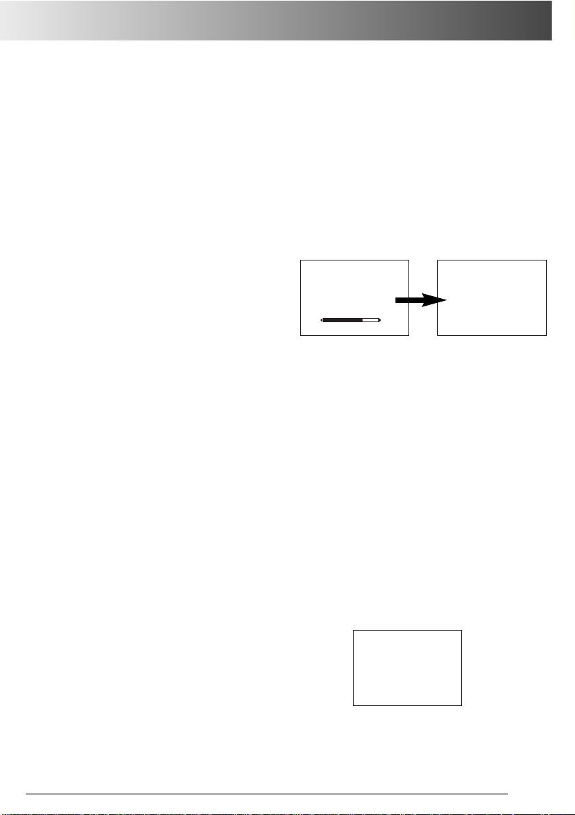
Automatic setting up channels
This TV set provides a self-automatic tuning and
sorting system function called “Plug & Play”. It
automatically begins searching and storing of all
available channels when switching-on the TV set
for the first time.
Let’s start !
Connect power cord of the TV set to a wall
outlet, and turn on the TV set by pressing the
1
1
Mains ON/OFF button. Self-automatic tuning
system will be started as follows;
I AM SEARCHING.
ALL PROGRAMMES.
PLEASE WAIT.
1
After completing this procedure, the programme
position 1 is selected and the ending messages on
the screen.
Note: The Plug & Play can be cancelled at any
time by pressing the MENU button.
Press any of the control buttons to make the
ending message disappear. Or will
2
2
automatically return to normal TV display
after 10 seconds.
✐ This procedure only appears at the first
switch-on time.
■ If no TV stations are found, the display shown
below will appear. Please check if the antenna
is connected properly.
AUTO SET-UP
COMPLETED.
HAPPY VIEWING !
NO STATION.
PLEASE CONNECT
ANTENNA PLUG.
If it isn’t connected properly, connect antenna and
Automatic Tuning will be reset.
3
ont Controlol
FrFront Contr
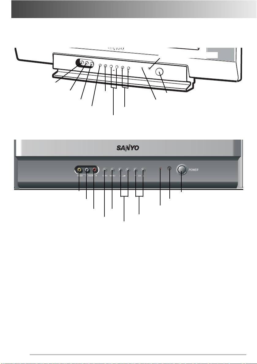
Each button listed in this section has the same function as it’s corresponding button on the remote control.
Model CA14SE1(V), CP14SE1(V), CA21SE1(V), CP21SE1(V), CA21VF1, CP21VF1,
CA21VF1K, CP21VF1K
Remote Control Detector
T
VI
V/A
D
EO
V
MEN
L-AU
D
U
-
I
O-R
+
C
H
POW
ER
Video Input Jack (AV2)
Audio Input Jack-Left (AV2)
Audio Input Jack-Right (AV2)
TV/AV Selector
MENU
Mains ON/OFF Button
Stand-by and Power Indicator
Programme UP/DOWN
VOLUME
Model CA21CF1(V), CP21CF1(V)
Video Input Jack (AV2)
Audio Input Jack-Left (AV2)
Audio Input Jack-Right (AV2)
4
MENU
TV/AV Selector
Mains ON/OFF Button
Remote Control Detector
Stand-by and Power Indicator
Programme UP/DOWN
VOLUME
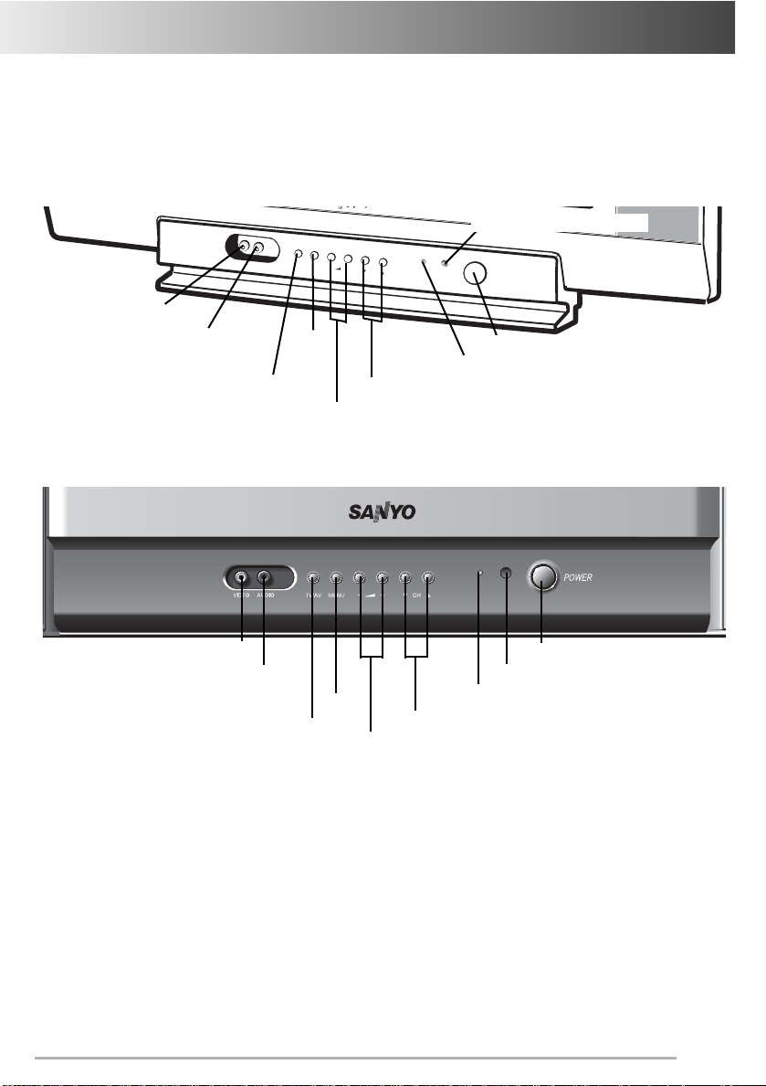
ont Controlol
FrFront Contr
Each button listed in this section has the same function as it’s corresponding button on the remote control.
Monaural Model
Model CA14SE1M, CP14SE1M, CA14SE1K, CP14SE1K, CA21SE1M, CP21SE1M,
CA21SE1K, CP21SE1K
Remote Control Detector
VI
D
EO
AU
D
I
O
Video Input Jack (AV2)
Audio Input Jack (AV2)
TV/AV Selector
Model CA21CF1M, CP21CF1M
Video Input Jack (AV2)
Audio Input Jack (AV2)
TV/AV Selector
T
V/
AV
MEN
MENU
U
-
+
C
H
Stand-by and Power Indicator
Programme UP/DOWN
VOLUME
MENU
Programme UP/DOWN
VOLUME
POW
ER
Mains ON/OFF Button
Mains ON/OFF Button
Remote Control Detector
Stand-by and Power Indicator
5
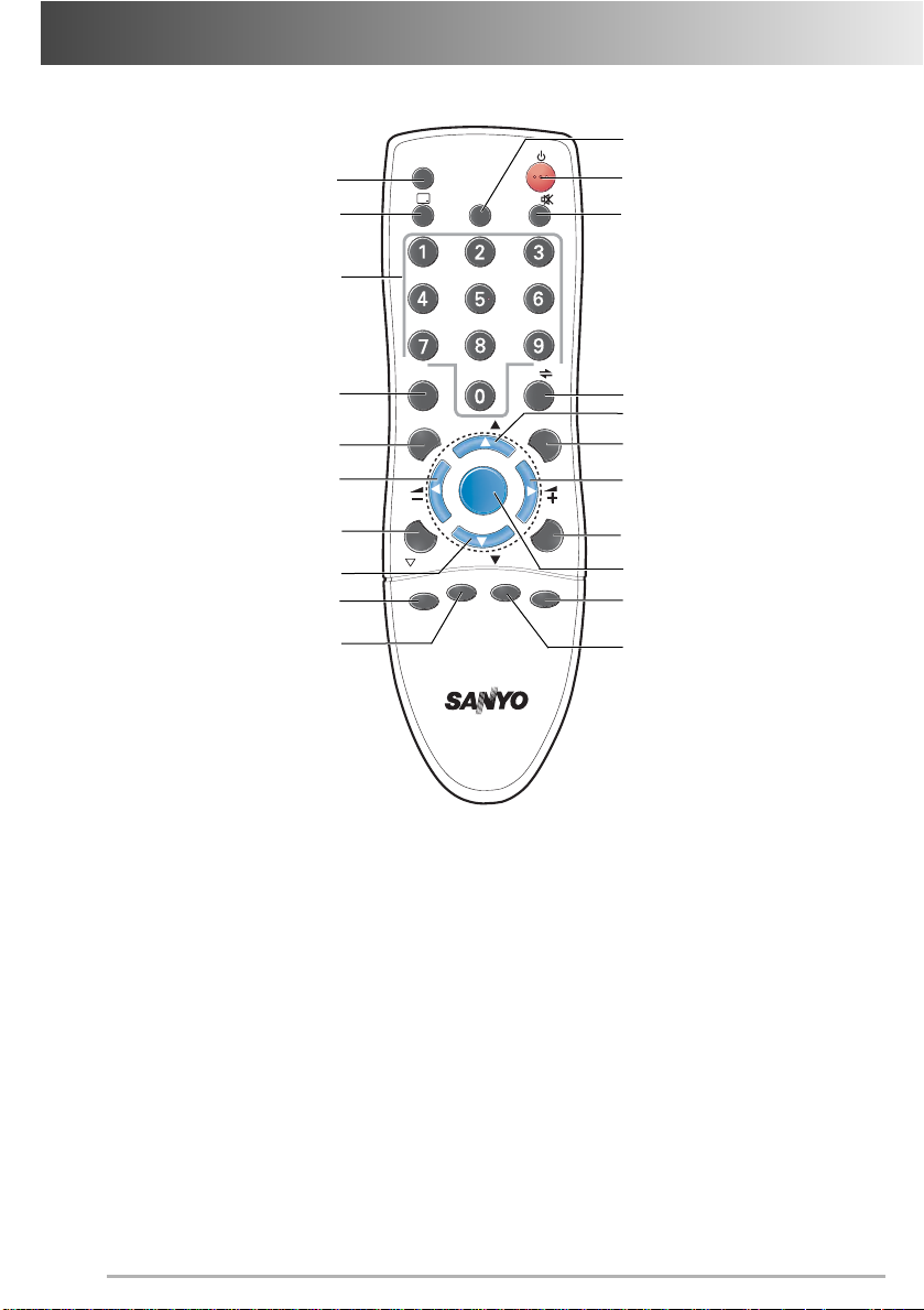
Remote Contr
-/- -
Remote Contr
ol T
ransmitter
ol T
ransmitter
TV / AV Selector button
RECALL/COLOUR SYSTEM button
Programme Selector button
DIGIT button
SWAP button
VOLUME - button
STEREO/MONO button
(This button is not used)
Programme DOWN button
* BASS EXPANDER button
* SOUND MODE button
TV / AV
-/- -
SWAP
A•B
BASS
SOUND
TIMER
CH
MENU
CH
JXPSC
S. SYS
P
P
CH SCAN
PICTURE
SURROUND
TIMER button
Power ON/OFF button
MUTE button
ALTERNATE button
Programme UP button
CHANNEL SCAN button
VOLUME + button
PICTURE MODE button
MENU button
* SURROUND button
SOUND SYSTEM button
* For monaural models this button is not used.
Battery Installation of the Remote Control Transmitter
1. Open the battery cover.
2. Install two “AA” 1.5 volt batteries so that the “+” and “-” marks on the batteries match the “+” and
“ - ” marks inside the unit.
3. Close the battery cover.
Note: Replace the batteries when the TV set is showing the following symptoms:
Operation is unsteady or erratic, sometimes the TV set does not work with transmitter.
Discharged batteries may leak and damage the unit. The normal life of batteries should be from
nine to ten months.
6
 Loading...