


LFD DISPLAY
User Manual
ED32C ED40C ED46C ED55C
The color and the appearance may differ depending on the product, and the specifications are subject to change without prior notice to improve the performance.

Table of contents
Before Using the Product
Copyright |
5 |
|
|
Safety Precautions |
6 |
Symbols |
6 |
Cleaning |
6 |
Storage |
7 |
Electricity and Safety |
7 |
Installation |
8 |
Operation |
10 |
Preparations
Checking the Contents |
13 |
Removing the Packaging (for ED32C, ED40C and |
|
ED46C models only) |
13 |
Removing the Packaging |
|
(for ED55C models only) |
14 |
Checking the Components |
15 |
Parts |
16 |
Reverse Side |
16 |
Anti-theft Lock |
17 |
Remote Control |
18 |
Before Installing the Product |
|
(Installation Guide) |
21 |
Tilting Angle and Rotation |
21 |
Ventilation |
21 |
|
|
Dimensions |
22 |
|
|
Installing the Wall Mount |
23 |
Installing the Wall Mount Kit |
23 |
Wall Mount Kit Specifications (VESA) |
24 |
|
|
Remote Control (RS232C) |
25 |
Cable Connection |
25 |
Connection |
27 |
Control Codes |
28 |
Connecting and Using a Source
Device
Before Connecting |
37 |
Pre-connection Checkpoints |
37 |
|
|
Connecting to a PC |
38 |
Connection using the D-SUB cable |
|
(Analog type) |
38 |
Connection Using an HDMI-DVI Cable |
39 |
Connection Using an HDMI Cable |
39 |
Changing the Resolution |
40 |
Changing the Resolution on Windows XP |
40 |
Changing the Resolution on Windows Vista |
40 |
Changing the Resolution on Windows 7 |
41 |
Changing the Resolution on Windows 8 |
41 |
|
|
Connecting to a Video Device |
42 |
Connection Using an HDMI-DVI Cable |
42 |
Connection Using an HDMI Cable |
43 |
|
|
Connecting to an Audio System |
44 |
|
|
Changing the Input source |
45 |
Source |
45 |
Using MDC
Configuring Settings for Multi Control |
46 |
Configuring settings for Multi Control |
46 |
|
|
MDC Program Installation/Uninstallation |
47 |
Installation |
47 |
Uninstallation |
47 |
|
|
What is MDC? |
48 |
Connecting to MDC |
48 |
Connection Management |
49 |
User Login |
50 |
Auto Set ID |
51 |
Cloning |
52 |
Command Retry |
53 |
|
|
Getting Started with MDC |
54 |
Main Screen Layout |
55 |
Menus |
55 |
Screen Adjustment |
57 |
Advanced features |
60 |
Sound Adjustment |
62 |
System Setup |
62 |
Tool Settings |
71 |
Other Functions |
74 |
Group Management |
75 |
Schedule Management |
77 |
Troubleshooting Guide |
79 |
2

Table of contents
Screen Adjustment
Picture Mode |
81 |
If the input source is PC, HDMI(PC) |
81 |
If the input source is HDMI(AV) |
81 |
|
|
Backlight / Contrast / Brightness / Sharpness / |
|
Color / Tint (G/R) |
82 |
|
|
Picture Size |
83 |
Picture Size |
83 |
Position |
84 |
Resolution Select |
84 |
|
|
Auto Adjustment |
85 |
|
|
PC Screen Adjustment |
85 |
|
|
PIP |
86 |
|
|
Advanced Settings |
87 |
Dynamic Contrast |
87 |
Black Tone |
87 |
Flesh Tone |
87 |
RGB Only Mode |
87 |
Color Space |
87 |
White Balance |
88 |
Gamma |
88 |
Motion Lighting |
88 |
Color Tone |
90 |
Color Temp. |
90 |
Digital Clean View |
90 |
MPEG Noise Filter |
90 |
HDMI Black Level |
91 |
Film Mode |
91 |
Dynamic Backlight |
91 |
Picture Off |
92 |
|
|
Reset Picture |
92 |
Sound Adjustment
Sound Mode |
93 |
|
|
Sound Effect |
94 |
|
|
Speaker Settings |
95 |
|
|
Reset Sound |
95 |
Applications
Source List |
96 |
Refresh |
96 |
Edit Name |
96 |
Information |
96 |
System
Menu Language |
97 |
|
|
Multi Control |
98 |
Configuring settings for Multi Control |
98 |
|
|
Time |
99 |
Clock Set |
99 |
Sleep Timer |
99 |
On Timer |
100 |
Off Timer |
101 |
Holiday Management |
101 |
|
|
Eco Solution |
102 |
Energy Saving |
102 |
Eco Sensor |
102 |
Auto Power Off |
102 |
|
|
Screen Burn Protection |
103 |
Pixel Shift |
103 |
Timer |
104 |
Immediate Display |
105 |
Side Gray |
105 |
|
|
Ticker |
106 |
|
|
Video Wall |
107 |
Video Wall |
107 |
Format |
107 |
Horizontal |
107 |
Vertical |
108 |
Screen Position |
108 |
|
|
Source AutoSwitch Settings |
109 |
Source AutoSwitch |
109 |
Primary Source Recovery |
109 |
Primary Source |
109 |
Secondary Source |
109 |
|
|
General |
110 |
Max. Power Saving |
110 |
Game Mode |
110 |
Auto Power |
110 |
3

Table of contents
Safety Lock |
110 |
Button Lock |
111 |
Standby Control |
111 |
Lamp Schedule |
111 |
OSD Display |
112 |
Power On Adjustment |
112 |
Temperature Control |
112 |
|
|
Change PIN |
113 |
|
|
Anynet+ (HDMI-CEC) |
114 |
Anynet+ (HDMI-CEC) |
114 |
Auto Turn Off |
115 |
Troubleshooting for Anynet+ |
116 |
|
|
Magic Clone |
118 |
|
|
Reset System |
118 |
|
|
Reset All |
119 |
Support
Software Update |
120 |
By USB |
120 |
|
|
Contact Samsung |
121 |
Troubleshooting Guide
Requirements Before Contacting Samsung |
|
Customer Service Center |
122 |
Testing the Product |
122 |
Checking the Resolution and Frequency |
122 |
Check the followings. |
123 |
|
|
Q & A |
126 |
Specifications
General |
128 |
|
|
PowerSaver |
130 |
|
|
Preset Timing Modes |
131 |
Appendix
Contact SAMSUNG WORLD WIDE |
133 |
|
|
Responsibility for the Pay Service (Cost to |
|
Customers) |
142 |
Not a product defect |
142 |
A Product damage caused by customer's fault |
142 |
Others |
142 |
|
|
Correct Disposal |
143 |
Correct Disposal of This Product (Waste Electrical & |
|
Electronic Equipment) |
143 |
Correct disposal of batteries in this product |
143 |
|
|
Optimum Picture Quality and Afterimage Burn- |
|
in Prevention |
144 |
Optimum Picture Quality |
144 |
Prevention of Afterimage Burn-in |
145 |
|
|
License |
147 |
|
|
Terminology |
148 |
|
|
4

Chapter 01
Before Using the Product
Copyright
The contents of this manual are subject to change without notice to improve quality.
© 2013 Samsung Electronics
Samsung Electronics owns the copyright for this manual.
Use or reproduction of this manual in parts or entirety without the authorization of Samsung Electronics is prohibited.
Microsoft, Windows are registered trademarks of Microsoft Corporation.
VESA, DPM and DDC are registered trademarks of the Video Electronics Standards Association.
Ownership of all other trademarks is attributed to their due owner.
•• An administration fee may be charged if either
-- (a) an engineer is called out at your request and there is no defect in the product (i.e. where you have failed to read this user manual).
-- (b) you bring the unit to a repair center and there is no defect in the product (i.e. where you have failed to read this user manual).
•• The amount of such administration charge will be advised to you before any work or home visit is carried out.
5
Safety Precautions
Caution
RISK OF ELECTRIC SHOCK DO NOT OPEN
Caution : TO REDUCE THE RISK OF ELECTRIC SHOCK, DO NOT REMOVE COVER. (OR BACK) THERE ARE NO USER SERVICEABLE PARTS INSIDE.
REFER ALL SERVICING TO QUALIFIED PERSONNEL.
This symbol indicates that high voltage is present inside.
It is dangerous to make any kind of contact with any internal part of this product.
This symbol alerts you that important literature concerning operation and maintenance has been included with this product.
Symbols
Warning
A serious or fatal injury may result if instructions are not followed.
Caution
Personal injury or damage to properties may result if instructions are not followed.
Activities marked by this symbol are prohibited.
Instructions marked by this symbol must be followed.
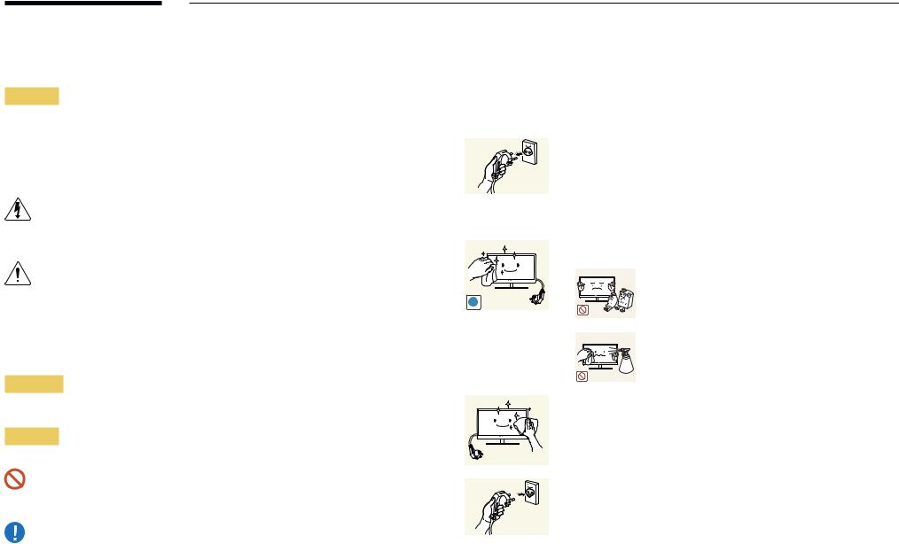
Cleaning
――Exercise care when cleaning as the panel and exterior of advanced LCDs are easily scratched. ――Take the following steps when cleaning.
――The following images are for reference only. Real-life situations may differ from what is shown in the images.
1 |
Power off the product and computer. |
2 |
Disconnect the power cord from the product. |
――Hold the power cable by the plug and do not touch the cable with wet hands. Otherwise, an electric shock may result.
3 Wipe the product with a clean, soft and dry cloth.
•• Do not use detergents that contain alcohol, solvent or
surface-active agents.
!
•• Do not spray water or detergent directly on the product.
4 Wet a soft and dry cloth in water and wring thoroughly to clean the exterior of the product.
5 |
Connect the power cord to the product when cleaning is finished. |
6 |
Power on the product and computer. |
6
Storage
High-glossy models can develop white stains on the surface if an ultrasonic wave humidifier is used nearby.
――Contact Customer Service Center if the inside of the product needs cleaning (service fee will be charged).
Electricity and Safety
――The following images are for reference only. Real-life situations may differ from what is shown in the images.
Warning
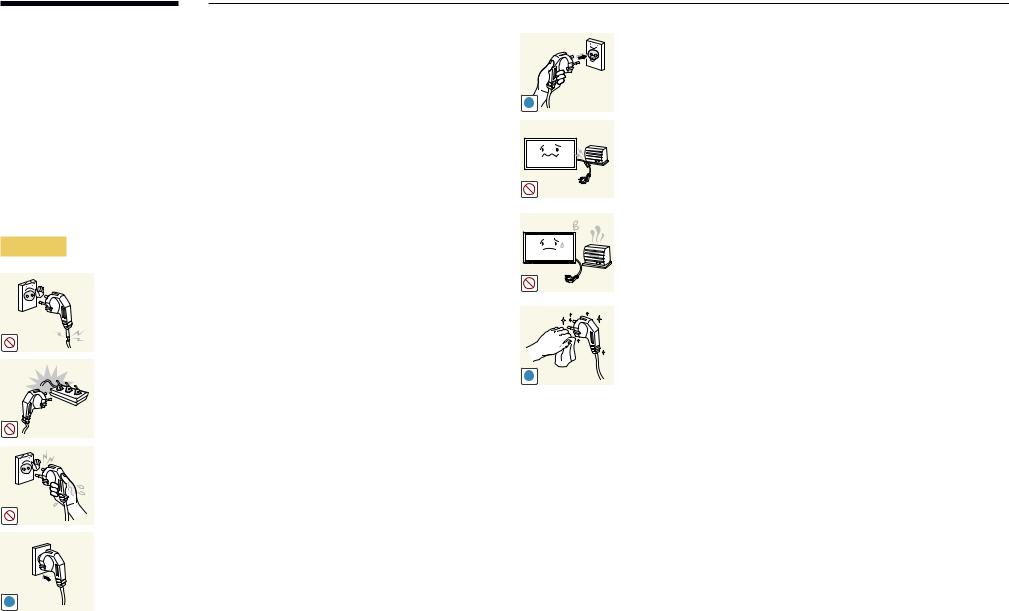
Do not use a damaged power cord or plug, or a loose power socket.
•• An electric shock or fire may result.
Do not use multiple products with a single power socket.
•• Overheated power sockets may cause a fire.
Do not touch the power plug with wet hands. Otherwise, an electric shock may result.
Insert the power plug all the way in so it is not loose.
•• An unsecure connection may cause a fire.
!
Connect the power plug to a grounded power socket (type 1 insulated devices only).
•• An electric shock or injury may result.
!
Do not bend or pull the power cord with force. Be careful not to leave the power cord under a heavy object.
•• Damage to the cord may result in a fire or electric shock.
Do not place the power cord or product near heat sources.
•• A fire or electric shock may result.
Clean any dust around the pins of the power plug or the power socket with a dry cloth.
•• A fire may result.
!
7
Caution
!
!
!
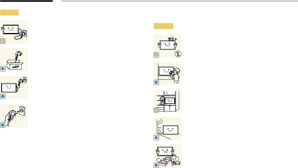
Do not disconnect the power cord while the product is being used.
•• The product may become damaged by an electric shock.
Only use the power cord provided with your product by Samsung. Do not use the power cord with other products.
•• A fire or electric shock may result.
Keep the power socket where the power cord is connected unobstructed.
•• The power cord must be disconnected to cut off power to the product when an issue occurs.
•• Note that the product is not completely powered down by using only the power button on the remote.
Hold the plug when disconnecting the power cord from the power socket.
•• An electric shock or fire may result.
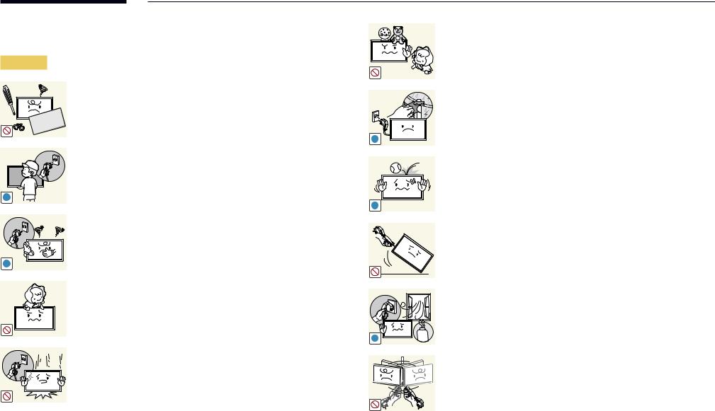
Installation
Warning
DO NOT PLACE CANDLES, INSECT REPELLANTS OR CIGARETTES ON TOP OF THE PRODUCT. DO NOT INSTALL THE PRODUCT NEAR HEAT SOURCES.
•• A fire may result.
Have a technician install the wall-mount hanger.
•• Installation by an unqualified person can result in an injury.
•• Only use approved cabinets.
!
Do not install the product in poorly ventilated spaces such as a bookcase or closet.
•• An increased internal temperature may cause a fire.
Install the product at least 10cm away from the wall to allow ventilation.
•• An increased internal temperature may cause a fire.
!
Keep the plastic packaging out of the reach of children.
•• Children may suffocate.
!
8
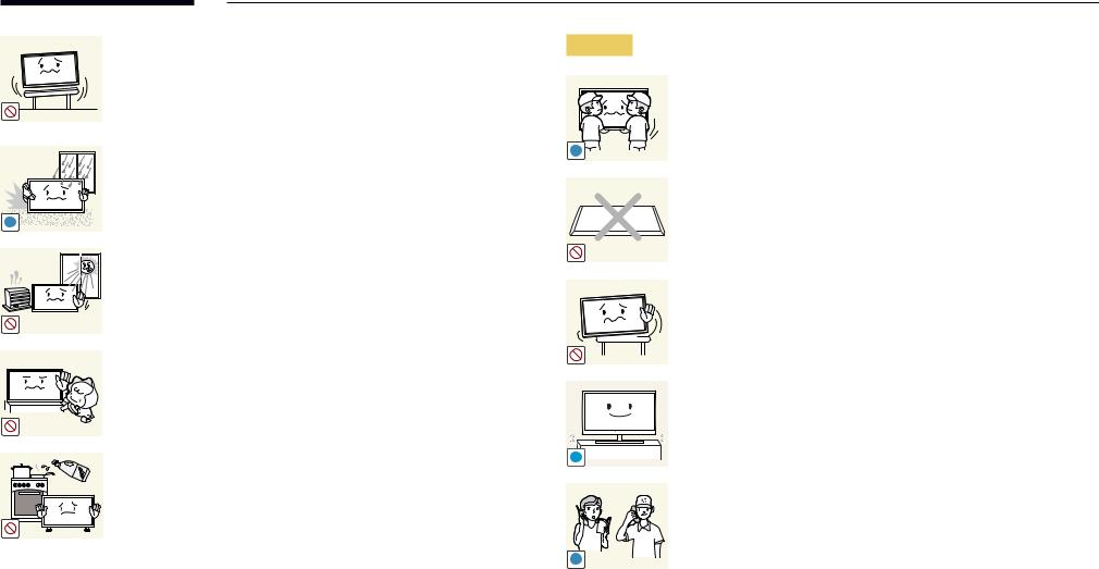
! |
Do not install the product on an unstable or vibrating surface (insecure shelf, |
Caution |
sloped surface, etc.) |
|
•• The product may fall and become damaged and/or cause an injury. |
|
•• Using the product in an area with excess vibration may damage the |
|
product or cause a fire. |
|
Do not install the product in a vehicle or a place exposed to dust, moisture |
! |
(water drips, etc.), oil, or smoke. |
|
•• A fire or electric shock may result. |
|
Do not expose the product to direct sunlight, heat, or a hot object such as a |
|
stove. |
|
•• The product lifespan may be reduced or a fire may result. |
|
Do not install the product within the reach of young children. |
|
•• The product may fall and injure children. |
|
•• As the front is heavy, install the product on a flat and stable surface. |
|
Edible oil, such as soybean oil, can damage or deform the product. Do not |
! |
install the product in a kitchen or near a kitchen counter. |
|
|
SAMSUNG |
|
! |
Do not drop the product while moving.
•• Product failure or personal injury may result.
Do not set down the product on its front.
•• The screen may become damaged.
When installing the product on a cabinet or shelf, make sure that the bottom edge of the front of the product is not protruding.
•• The product may fall and become damaged and/or cause an injury.
•• Install the product only on cabinets or shelves of the right size.
Set down the product gently.
•• Product failure or personal injury may result.
Installing the product in an unusual place (a place exposed to a lot of fine particles, chemical substances or extreme temperatures, or an airport
or train station where the product should operate continuously for an extended period of time) may seriously affect its performance.
•• Be sure to consult Samsung Customer Service Center if you want to install the product at such a place.
9
Operation
Warning
There is a high voltage inside the product. Never disassemble, repair or modify the product yourself.
•• A fire or electric shock may result.
•• Contact Samsung Customer Service Center for repairs.
!
Before moving the product, turn off the power switch and disconnect the power cable and all other connected cables.
•• Damage to the cord may result in a fire or electric shock.
!
!
If the product generates abnormal sounds, a burning smell or smoke,
disconnect the power cord immediately and contact Samsung Customer
Service Center.
•• An electric shock or fire may result.
!
Do not let children hang from the product or climb on top of it.
•• Children may become injured or seriously harmed.
!
If the product is dropped or the outer case is damaged, turn off the power switch and disconnect the power cord. Then contact Samsung Customer Service Center.
•• Continued use can result in a fire or electric shock.
Do not leave heavy objects or items that children like (toys, sweets, etc.) on top of the product.
•• The product or heavy objects may fall as children try to reach for the toys or sweets resulting in a serious injury.
During a lightning or thunderstorm, power off the product and remove the power cable.
•• A fire or electric shock may result.
Do not drop objects on the product or apply impact.
•• A fire or electric shock may result.
Do not move the product by pulling the power cord or any cable.
•• Product failure, an electric shock or fire may result from a damaged cable.
If a gas leakage is found, do not touch the product or power plug. Also, ventilate the area immediately.
•• Sparks can cause an explosion or fire.
GAS
Do not lift or move the product by pulling the power cord or any cable.
•• Product failure, an electric shock or fire may result from a damaged cable.
10
Do not use or keep combustible spray or an inflammable substance near the product.
•• An explosion or fire may result.
!
Ensure the vents are not blocked by tablecloths or curtains.
•• An increased internal temperature may cause a fire.
|
Do not insert metallic objects (chopsticks, coins, hairpins, etc) or objects |
100 |
that burn easily (paper, matches, etc) into the product (via the vent or input/ |
|
output ports, etc). |
•• Be sure to power off the product and disconnect the power cord when water or other foreign substances have entered the product. Then contact Samsung Customer Service Center.
•• Product failure, an electric shock or fire may result.
Do not place objects containing liquid (vases, pots, bottles, etc) or metallic objects on top of the product.
•• Be sure to power off the product and disconnect the power cord when water or other foreign substances have entered the product. Then contact Samsung Customer Service Center.
•• Product failure, an electric shock or fire may result.
Caution
!
-_-
!
!
!
Leaving the screen fixed on a stationary image for an extended period of time may cause afterimage burn-in or defective pixels.
•• Activate power-saving mode or a moving-picture screen saver if you will not be using the product for an extended period of time.
Disconnect the power cord from the power socket if you do not plan on using the product for an extended period of time (vacation, etc).
•• Dust accumulation combined with heat can cause a fire, electric shock or electric leakage.
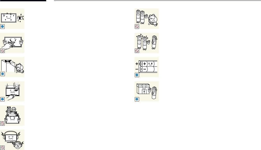
Use the product at the recommended resolution and frequency.
•• Your eyesight may deteriorate.
Do not hold the product upside-down or move it by holding the stand.
•• The product may fall and become damaged or cause an injury.
Looking at the screen too close for an extended period of time can deteriorate your eyesight.
Do not use humidifiers or stoves around the product.
•• A fire or electric shock may result.
11
Rest your eyes for more than 5 minutes for every 1 hour of product use.
•• Eye fatigue will be relieved.
!
Do not touch the screen when the product has been turned on for an extended period of time as it will become hot.
Store small accessories out of the reach of children.
!
Exercise caution when adjusting the product angle or stand height.
•• Your hand or finger may get stuck and injured.
•• Tilting the product at an excessive angle may cause the product to fall
and an injury may result.
!
Do not place heavy objects on the product.
•• Product failure or personal injury may result.
When using headphones or earphones, do not turn the volume too high.
•• Having the sound too loud may damage your hearing.
Be careful that children do not place the battery in their mouths when removed from the remote control. Place the battery in a location that children or infants cannot reach.
•• If children have had the battery in their mouths, consult your doctor immediately.
When replacing the battery, insert it with the right polarity (+, -).
•• Otherwise, the battery may become damaged or it may cause fire, personal injury or damage due to leakage of the internal liquid.
Use only the specified standardized batteries, and do not use a new battery and a used battery at the same time.
•• Otherwise, the batteries may be damaged or cause fire, personal injury or damage due to a leakage of the internal liquid.
!
The batteries (and rechargeable batteries) are not ordinary refuse and must be returned for recycling purposes. The customer is responsible for returning
the used or rechargeable batteries for recycling.
•• The customer can return used or rechargeable batteries to a nearby !  public recycling center or to a store selling the same type of the
battery or rechargeable battery.
12
Chapter 02
Preparations
Checking the Contents
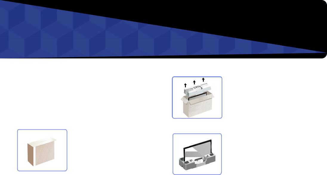
Removing the Packaging (for ED32C, ED40C and ED46C models only)
――This image is for reference only.
1 Open the packaging box. Be careful not to damage the product when you open the packaging with a sharp instrument.
2
3
4
Remove the styrofoam from the product.
Check the product and remove the styrofoam and plastic bag.
Store the box in a dry area so that it can be used when moving the product in the future.
13

Removing the Packaging(for ED55C models only)
――The following images are for reference only. Real-life situations may differ from what is shown in the images.
1 Remove the black locking device at the bottom of the box. |
|
|
1 |
2 |
3 |
2 Using the grooves in the box, lift and remove the top of the box.
3 Check the components and remove the styrofoam and plastic bag.
――The appearance of actual components may differ from the image shown.
4 Store the box in a dry area so that it can be used when moving the product in the future.
14
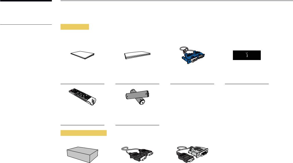
-- Contact the vendor where you purchased the product if any components are missing.
-- The appearance of the components and items sold separately may differ from the image shown.
-- A stand is not provided with the product. To install a stand, you can purchase one separately.
Checking the Components
Components
――Components may differ in different locations.
Quick setup guide |
Warranty card |
D-SUB cable (P.38) |
Power cord |
|
(Not available in some |
|
|
|
locations) |
|
|
|
- |
|
|
|
+ |
|
|
|
- |
|
|
|
+ |
|
|
Remote Control (P.18) |
Batteries (P.19) |
|
|
(AA59-00714A) |
(Not available in some |
|
|
|
locations) |
|
|
Items sold separately
Wall-mount Kit |
|
HDMI cable (P.39) |
|
HDMI-DVI cable (P.39) |
|
|
|
|
|
15
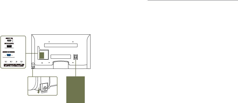
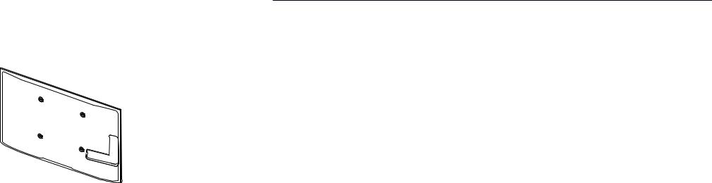
Parts
Reverse Side
Remote Sensor
POWER
Port |
Description |
|
|
HDMI IN |
Connects to a source device using an HDMI cable. |
|
|
SERVICE (5V 0.5A) |
This port is used to upgrade the software. |
|
|
RGB IN |
Connects to a source device using a D-SUB cable. |
|
|
AUDIO OUT |
Connects to the audio of a source device. |
|
|
RGB / HDMI AUDIO IN |
Receives sound from a PC via an audio cable. |
|
|
RS232C IN |
Connects to MDC using an RS232C-stereo adapter. |
|
|
RS232C OUT |
|
|
|
Remote Sensor |
To control the remote control in front of the product, lower the remote control |
|
sensor in the direction of the arrow. |
|
|
16

Anti-theft Lock
――An anti-theft lock allows you to use the product securely even in public places.
――The locking device shape and locking method depend on the manufacturer. Refer to the user guide provided with your anti-theft locking device for details.
To lock an anti-theft locking device:
――Stand: Sold separately
1
2
3
4
Fix the cable of your anti-theft locking device to a heavy object such as a desk.
Put one end of the cable through the loop on the other end.
Insert the locking device into the anti-theft lock slot at the back of the product.
Lock the locking device.
-- An anti-theft locking device can be purchased separately.
-- Refer to the user guide provided with your anti-theft locking device for details. -- Anti-theft locking devices can be purchased at electronics retailers or online.
17
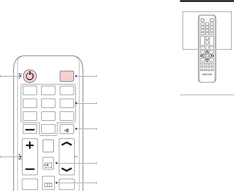
Remote Control
――Using other display devices in the same space as the remote control of this product can cause the other display devices to be inadvertently controlled.
Power on the product. |
|
OFF |
.QZ |
ABC |
DEF |
1 |
2 |
3 |
GHI |
JKL |
MNO |
4 |
5 |
6 |
PRS |
TUV |
WXY |
7 |
8 |
9 |
DEL-/-- |
SYMBOL |
MUTE |
|
0 |
|
CONTENT
(HOME)
Adjust the volume. |
VOL |
SOURCE |
CH |
|
|
|
MENU
MagicInfo |
BLANK |
|
Lite |
||
|
Power off the product.
Enter the password in the OSD menu.
Mute the sound.
Unmuting the sound: Press MUTE again or press the volume control (+ VOL -) button.
Select a connected source device.
Display or hide the onscreen display menu, or return to the previous menu.
-- Remote control button functions may differ for different products.
18

Quickly select frequently used functions. |
TOOLS |
INFO |
|
|
Return to the previous menu. |
RETURN |
|
|
EXIT |
|
|
|
|
|
|
PC |
DVI |
HDMI |
DP |
|
A |
B |
C |
D |
|
MAGICINFO |
3D |
LOCK |
|
To place batteries in the remote control
Display information on the screen.
Move to the upper, lower, left or right menu, or adjust an option's setting.
Confirm a menu selection.
Exit the current menu.
Manually select a connected input source from
PC, HDMI.
It sets safe lock function.
-- Remote control button functions may differ for different products.
19
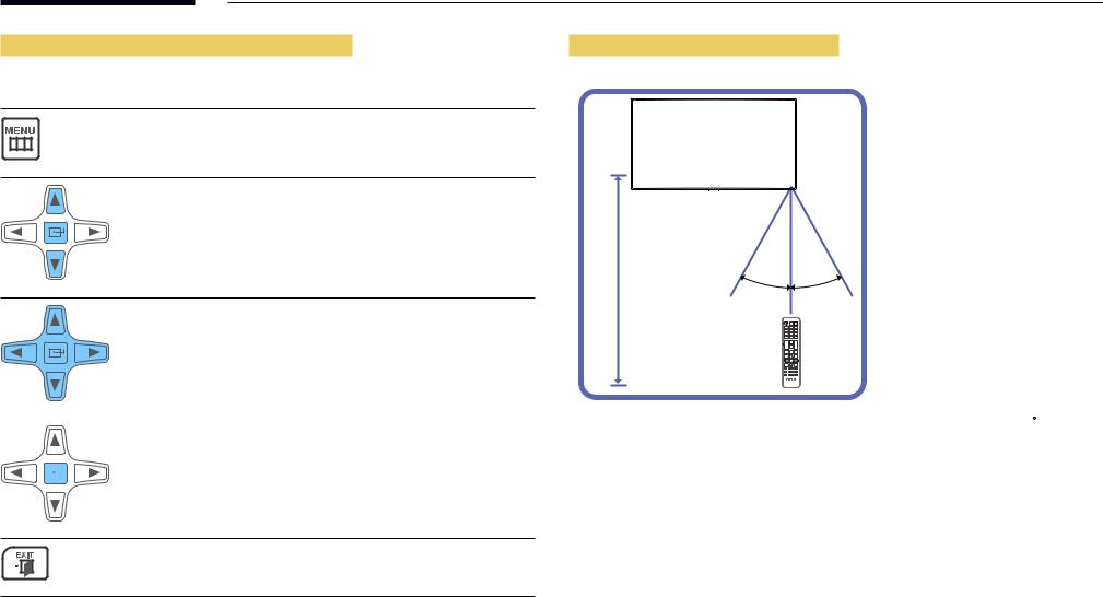
Adjusting the OSD with the Remote Control
Buttons |
Description |
|
|
1 |
Open the OSD menu. |
|
2 |
Select from Picture, Sound, Applications, System or |
|
|
Support in the displayed OSD menu screen. |
3 Change settings as desired.
Remote Control Reception Range
~ 10m |
30˚ |
30˚ |
|
7m |
|||
|
|
4 |
Finish setting. |
|||||||
|
|
|
|
|
|
|
|
|
5 Close the onscreen display (OSD) menu.
Use the remote control within 7m to 10m from the sensor on the product at an angle of 30 from the left and right.
――Store used batteries out of reach of children and recycle.
――Do not use a new and used battery together. Replace both batteries at the same time. ――Remove batteries when the remote control is not to be used for an extended period of time.
20
Before Installing the Product
(Installation Guide)
15 ˚
A 
B
Figure 1.1 Side view
To prevent injury, this apparatus must be securely attached to the floor/wall in accordance with the installation instructions.
•• Ensure that an authorized installation company installs the wall mount.
•• Otherwise, it may fall and cause personal injury.
•• Make sure to install the specified wall mount.
Tilting Angle and Rotation
――Contact Samsung Customer Service Center for further details.
•• The product can be tilted at a maximum angle of 15 from a perpendicular wall surface.
•• To use the product vertically (portrait), turn it clockwise so that the LED is pointing down.
Ventilation
Installation on a Perpendicular Wall
A Minimum 40 mm
B Ambient temperature: Under 35 C
•• When installing the product on a perpendicular wall, allow at least 40 mm of space between the product and wall surface for ventilation and ensure that the ambient A temperature is kept below 35 C.
21
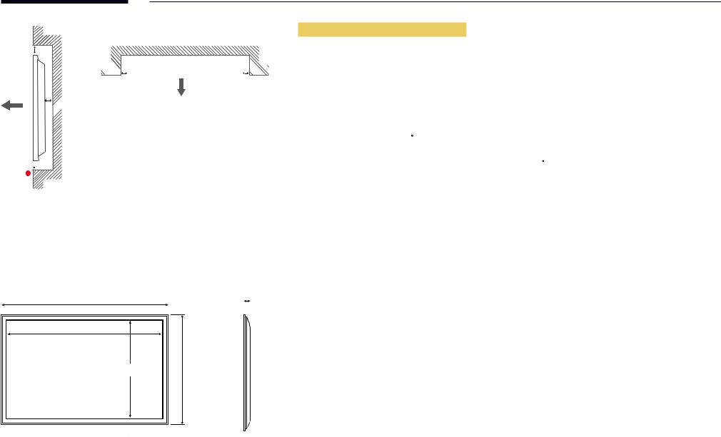
B |
A 
 C
C
E |
Figure 1.2 Side view
Figure 1.3 Side view

 D
D  D
D 

Installation on an Indented Wall
――Contact Samsung Customer Service Center for further details.
Plane view
A Minimum 40 mm B Minimum 70 mm C Minimum 50 mm D Minimum 50 mm
E Ambient temperature: Under 35 C
――When installing the product on an indented wall, allow at least the space specified above between the product and wall for ventilation and ensure that the ambient temperature is kept below 35 C.
Dimensions
|
|
|
|
Unit: mm (inches) |
Model name 1 |
2 |
3 |
4 |
5 |
|
|
5 |
ED32C |
736.0 (29.0) |
703.4 (27.7) |
397.8 (15.7) |
434.5 (17.1) |
93.7 (3.7) |
|||
|
|
1 |
|
|
|
|
|
|
|
|
|
|
|
|
|
|
ED40C |
925.4 (36.4) |
890.6 (35.1) |
503.2 (19.8) |
541.0 (21.3) |
93.6 (3.7) |
|
|
|
|
|
|
|
||||||
|
|
|
|
|
|
||||||
|
|
|
|
|
|
|
|
|
|
|
|
2 |
|
|
|
|
|
|
|
|
|
|
|
|
|
|
|
|
ED46C |
1057.7 (41.6) |
1023.0 (40.3) |
577.6 (22.7) |
615.8 (24.2) |
94.8 (3.7) |
|
|
|
|
4 |
|
|||||||
|
|
|
|
||||||||
|
|
|
|
|
|
|
|
|
|
|
|
|
|
3 |
|
|
ED55C |
1247.7 (49.1) |
1213.6 (47.8) |
684.4 (26.9) |
722.9 (28.5) |
94.8 (3.7) |
|
|
|
|
|
|
|
|
|
|
|
||
――All drawings are not necessarily to scale. Some dimensions are subject to change without prior notice.
Refer to the dimensions prior to performing installation of your product. Not responsible for typographical or printed errors.
22
Installing the Wall Mount Installing the Wall Mount Kit
The wall mount kit (sold separately) allows you to mount the product on the wall.
For detailed information on installing the wall mount, see the instructions provided with the wall mount. We recommend you contact a technician for assistance when installing the wall mount bracket.
Samsung Electronics is not responsible for any damage to the product or injury to yourself or others if you elect to install the wall mount on your own.


 1
1
23
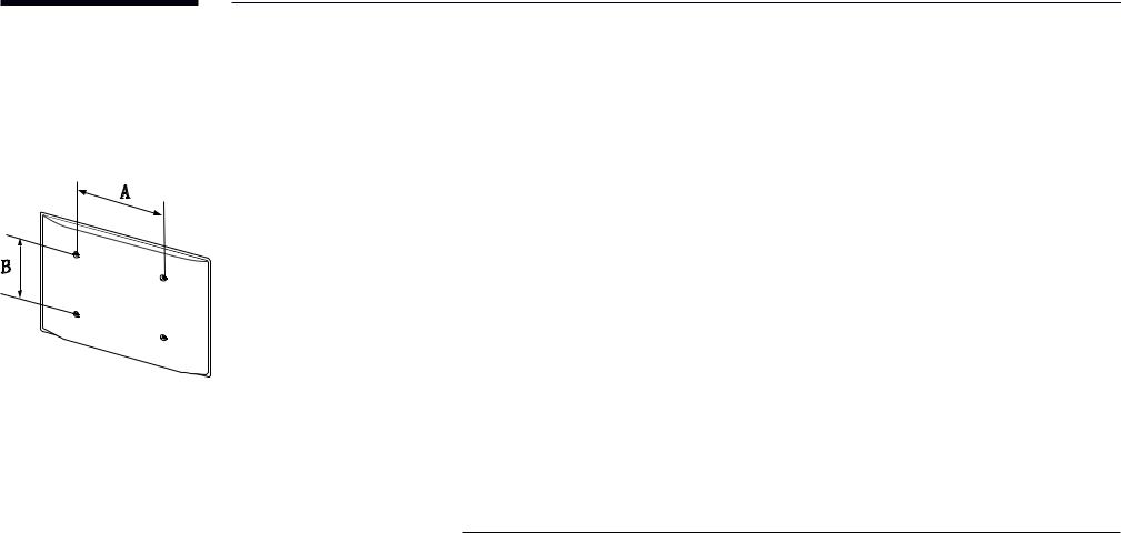
Wall Mount Kit Specifications (VESA)
――Install your wall mount on a solid wall perpendicular to the floor. Before attaching the wall mount to surfaces other than plaster board, please contact your nearest dealer for additional information.
If you install the product on a slanted wall, it may fall and result in severe personal injury.
•• Samsung wall mount kits contain a detailed installation manual and all parts necessary for assembly are provided.
•• Do not use screws that are longer than the standard length or do not comply with the VESA standard screw specifications. Screws that are too long may cause damage to the inside of the product.
•• For wall mounts that do not comply with the VESA standard screw specifications, the length of the screws may differ depending on the wall mount specifications.
•• Do not fasten the screws too firmly. This may damage the product or cause the product to fall, leading to personal injury. Samsung is not liable for these kinds of accidents.
•• Samsung is not liable for product damage or personal injury when a non-VESA or non-specified wall mount is used or the consumer fails to follow the product installation instructions.
•• Do not mount the product at more than a 15 degree tilt.
•• Always have two people mount the product on a wall.
•• Standard dimensions for wall mount kits are shown in the table below.
Unit: mm (inches)
Model name |
VESA screw hole |
Standard Screw |
Quantity |
|
|
specs (A * B) in |
|
|
|
|
millimeters |
|
|
|
|
|
|
|
|
ED32C |
200 x 200 |
(7.9 x 7.9) |
M6, L29 |
4EA |
|
|
|
|
|
ED40C |
|
|
|
|
|
|
|
|
|
ED46C |
400 x 400 |
(15.7 x 15.7) |
M8, L32 |
|
|
|
|
|
|
ED55C |
|
|
|
|
――Do not install your Wall Mount Kit while your product is turned on. It may result in personal injury due to electric shock.
24

Remote Control (RS232C)
Cable Connection
RS232C Cable
Interface |
RS232C (9 pins) |
|
|
Pin |
TxD (No.2), RxD (No.3), GND (No.5) |
|
|
Bit rate |
9600 bps |
|
|
Data bits |
8 bit |
|
|
Parity |
None |
|
|
Stop bit |
1 bit |
|
|
Flow control |
None |
|
|
Maximum length |
15 m (only shielded type) |
|
|
•• Pin assignment
1 2 3 4 5
6 |
7 |
8 |
9 |
Pin |
Signal |
|
|
1 |
Detect data carrier |
|
|
2 |
Received data |
|
|
3 |
Transmitted data |
|
|
4 |
Prepare data terminal |
|
|
5 |
Signal ground |
|
|
6 |
Prepare data set |
|
|
7 |
Send request |
|
|
8 |
Clear to send |
|
|
9 |
Ring indicator |
|
|
25
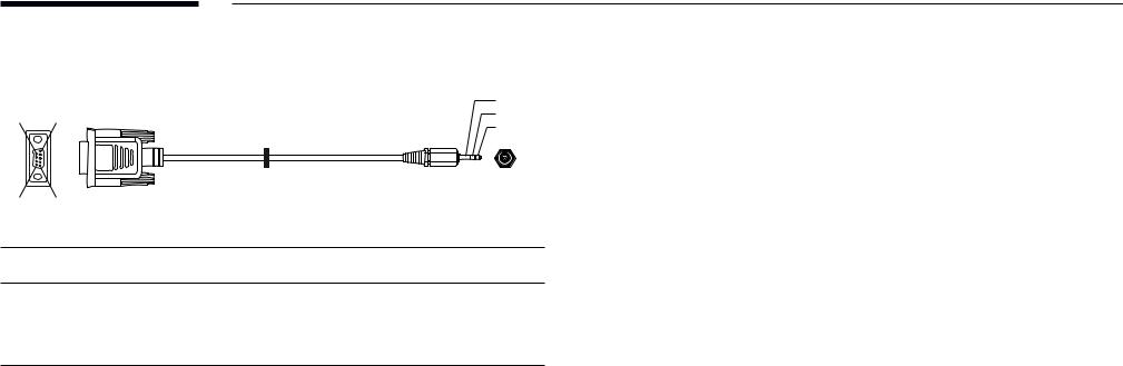
•• RS232C cable
Connector: 9-Pin D-Sub to Stereo Cable
3
9 5 2
1
|
|
|
|
|
|
-P2- |
6 |
1 |
|
|
|
|
|
-P1- |
|
|
|
|
|
|
-P1- |
|
-P1- |
|
-P2- |
|
-P2- |
Female |
Rx |
2 |
--------> |
3 |
Tx |
STEREO |
|
Tx |
3 |
<-------- |
2 |
Rx |
PLUG |
|
Gnd |
5 |
---------- |
5 |
Gnd |
(3.5ø) |
26

Connection
•• Connection 1
|
RS232C |
|
RS232C |
|
RS232C |
|
RS232C |
IN |
OUT |
IN |
OUT |
IN |
OUT |
IN |
OUT |
27

Control Codes
Viewing control state (Get control command)
Header |
Command |
ID |
Data length |
Checksum |
|
|
|
|
|
0xAA |
Command type |
|
0 |
|
Controlling (Set control command)
Header |
Command |
ID |
Data length |
Data |
Checksum |
|
|
|
|
|
|
0xAA |
Command type |
|
1 |
Value |
|
Command
No. |
Command type |
Command |
Value range |
|
|
|
|
1 |
Power control |
0x11 |
0~1 |
|
|
|
|
2 |
Volume control |
0x12 |
0~100 |
|
|
|
|
3 |
Input source control |
0x14 |
- |
|
|
|
|
4 |
Screen mode control |
0x18 |
- |
|
|
|
|
5 |
Screen size control |
0x19 |
0~255 |
|
|
|
|
6 |
PIP on/off control |
0x3C |
0~1 |
|
|
|
|
7 |
Auto adjustment control (PC and |
0x3D |
0 |
|
BNC only) |
|
|
|
|
|
|
8 |
Video wall mode control |
0x5C |
0~1 |
|
|
|
|
9 |
Safety Lock |
0x5D |
0~1 |
No. |
Command type |
Command |
Value range |
|
|
|
|
10 |
Video Wall On |
0x84 |
0~1 |
|
|
|
|
11 |
Video Wall User Control |
0x89 |
- |
•• All communications take place in hexadecimals. The checksum is calculated by adding up all values except the header. If a checksum adds up to be more than 2 digits as shown below (11+FF+01+01=112), the first digit is removed.
E.g. Power On & ID=0
Header |
Command |
ID |
Data length |
Data 1 |
Checksum |
|
|
|
|
|
|
0xAA |
0x11 |
|
1 |
"Power" |
|
|
|
|
|
|
|
|
|
|
|
|
|
Header |
Command |
ID |
Data length |
Data 1 |
12 |
|
|
|
|
|
|
0xAA |
0x11 |
|
1 |
1 |
|
•• To control all devices connected by a serial cable simultaneously irrespective of IDs, set the ID as "0xFE" and transmit commands. Commands will be executed by each device but ACK will not respond.
28

Power control
•• |
Function |
|
|
|
|
|
A product can be powered on and off using a PC. |
|
|||
•• |
Viewing power state (Get Power ON / OFF Status) |
|
|||
|
|
|
|
|
|
Header |
Command |
ID |
Data length |
Checksum |
|
|
|
|
|
|
|
0xAA |
0x11 |
|
0 |
|
|
•• Setting power ON/Off (Set Power ON / OFF)
Header |
Command |
|
ID |
Data length |
|
Data |
|
Checksum |
|||||
|
|
|
|
|
|
|
|
|
|
|
|
|
|
0xAA |
0x11 |
|
|
|
1 |
|
"Power" |
|
|
|
|
|
|
|
|
|
|
|
|
|
|
|
|
|
|||
"Power": Power code to be set on a product. |
|
|
|
|
|
|
|
|
|||||
1: Power ON |
|
|
|
|
|
|
|
|
|
|
|
|
|
0: Power OFF |
|
|
|
|
|
|
|
|
|
|
|
|
|
•• Ack |
|
|
|
|
|
|
|
|
|
|
|
|
|
|
|
|
|
|
|
|
|
|
|
|
|||
Header |
Command |
ID |
|
Data length |
Ack/Nak |
r-CMD |
Val1 |
Checksum |
|||||
|
|
|
|
|
|
|
|
|
|
|
|
|
|
0xAA |
0xFF |
|
3 |
|
'A' |
0x11 |
"Power" |
|
|
|
|||
|
|
|
|
|
|
|
|
|
|
|
|||
"Power": Power code to be set on a product. |
|
|
|
|
|
|
|
|
|||||
•• Nak |
|
|
|
|
|
|
|
|
|
|
|
|
|
|
|
|
|
|
|
|
|
|
|
|
|||
Header |
Command |
ID |
|
Data length |
Ack/Nak |
r-CMD |
Val1 |
Checksum |
|||||
|
|
|
|
|
|
|
|
|
|
|
|
|
|
0xAA |
0xFF |
|
3 |
|
'N' |
0x11 |
"ERR" |
|
|
|
|||
"ERR" : A code showing what error has occurred.
Volume control
•• Function
The volume of a product can be adjusted using a PC.
•• Viewing volume state (Get Volume Status)
Header |
Command |
ID |
Data length |
Checksum |
|
|
|
|
|
0xAA |
0x12 |
|
0 |
|
•• Setting the volume (Set Volume)
Header |
Command |
ID |
Data length |
Data |
Checksum |
|
|
|
|
|
|
0xAA |
0x12 |
|
1 |
"Volume" |
|
"Volume": Volume value code to be set on a product. (0-100)
•• Ack
Header |
Command |
ID |
Data length |
Ack/Nak |
r-CMD |
Val1 |
Checksum |
|
|
|
|
|
|
|
|
0xAA |
0xFF |
|
3 |
'A' |
0x12 |
"Volume" |
|
"Volume": Volume value code to be set on a product. (0-100)
•• Nak
Header |
Command |
ID |
Data length |
Ack/Nak |
r-CMD |
Val1 |
Checksum |
|
|
|
|
|
|
|
|
0xAA |
0xFF |
|
3 |
'N' |
0x12 |
"ERR" |
|
"ERR" : A code showing what error has occurred.
29

Input source control
•• |
Function |
|
|
|
|
|
|
The input source of a product can be changed using a PC. |
|
||||
•• |
Viewing input source state (Get Input Source Status) |
|
||||
|
|
|
|
|
|
|
Header |
Command |
ID |
Data length |
Checksum |
||
|
|
|
|
|
|
|
0xAA |
0x14 |
|
0 |
|
|
|
•• Setting the input source (Set Input Source)
Header |
Command |
ID |
Data length |
Data |
Checksum |
|
|
|
|
|
|
0xAA |
0x14 |
|
1 |
"Input Source" |
|
"Input Source": An input source code to be set on a product.
0x14 |
PC |
|
|
0x18 |
DVI |
|
|
0x0C |
Input source |
|
|
0x08 |
Component |
|
|
0x20 |
MagicInfo |
|
|
0x1F |
DVI_video |
|
|
0x30 |
RF(TV) |
|
|
0x40 |
DTV |
|
|
0x21 |
HDMI1 |
|
|
0x22 |
HDMI1_PC |
|
|
0x23 |
HDMI2 |
|
|
0x24 |
HDMI2_PC |
|
|
0x25 |
DisplayPort |
――DVI_video, HDMI1_PC and HDMI2_PC cannot be used with the Set command. They only respond to "Get" commands.
――This model does not support HDMI1, HDMI1_PC, HDMI2 and HDMI2_PC ports. ――MagicInfo is only available with models that contain the MagicInfo function. ――RF(TV), DTV are only available with models that include a TV.
•• Ack
Header |
Command |
ID |
Data length |
Ack/Nak |
r-CMD |
Val1 |
Checksum |
|
|
|
|
|
|
|
|
0xAA |
0xFF |
|
3 |
'A' |
0x14 |
"Input |
|
|
|
|
|
|
|
Source" |
|
"Input Source": An input source code to be set on a product.
•• Nak
Header |
Command |
ID |
Data length |
Ack/Nak |
r-CMD |
Val1 |
Checksum |
|
|
|
|
|
|
|
|
0xAA |
0xFF |
|
3 |
'N' |
0x14 |
"ERR" |
|
"ERR" : A code showing what error has occurred.
30
 Loading...