


XP100 • XP200 • XP300
OWNERS MANUAL
A U D I O
Safety Instructions/Consignes de sécurité/Sicherheitsvorkehrungen/Instrucciones de seguridad
WARNING:To reduce the risk of fire or electric shock, do not expose this unit to rain or moisture.To reduce the hazard of electrical shock, do not remove cover or back. No user serviceable parts inside. Please refer all servicing to qualified personnel.The lightning flash with an arrowhead symbol within an equilateral triangle, is intended to alert the user to the presence of uninsulated "dangerous voltage" within the products enclosure that may be of sufficient magnitude to constitute a risk of electric shock to persons.The exclamation point within an equilateral triangle is intended to alert the user to the presence of important operating and maintenance (servicing) instructions in the literature accompanying the product.
Important Safety Instructions
1.Please read all instructions before operating the unit.
2.Keep these instructions for future reference.
3.Please heed all safety warnings.
4.Follow manufacturers instructions.
5.Do not use this unit near water or moisture.
6.Clean only with a damp cloth.
7.Do not block any of the ventilation openings. Install in accordance with the manufacturers instructions.
8.Do not install near any heat sources such as radiators, heat registers, stoves, or other apparatus (including amplifiers) that produce heat.
9.Do not defeat the safety purpose of the polarized or grounding-type plug. A polarized plug has two blades with one wider than the other. A grounding type plug has two blades and a third grounding prong.The wide blade or third prong is provided for your safety.When the provided plug does not fit your outlet, consult an electrician for replacement of the obsolete outlet.
10.Protect the power cord from being walked on and pinched particularly at plugs, convenience receptacles and at the point at which they exit from the unit.
11.Unplug this unit during lightning storms or when unused for long periods of time.
12.Refer all servicing to qualified personnel. Servicing is required when the unit has been damaged in any way, such as power supply cord or plug damage, or if liquid has been spilled or objects have fallen into the unit, the unit has been exposed to rain or moisture, does not operate normally, or has been dropped.
ATTENTION: Pour éviter tout risque d’électrocution ou d’incendie, ne pas exposer cet appareil à la pluie ou à l’humidité.Pourévitertoutrisqued’électrocution,nepasôterle couvercleouledosduboîtier.Cet appareil ne contient aucune pièce remplaçable par l'utilisateur. Confiez toutes les réparations à un personnel qualifié. Le signe avec un éclair dans un triangle prévient l’utilisateur de la présence d’une tension dangereuse et non isolée dans l’appareil. Cette tension constitue un risque d’électrocution. Le signe avec un point d’exclamation dans un triangle prévient l’utilisateur d’instructions importantes relatives à l’utilisation et à la maintenance du produit.
Consignes de sécurité importantes
1.Veuillez lire toutes les instructions avant d’utiliser l’appareil.
2.Conserver ces instructions pour toute lecture ultérieure.
3.Lisez avec attention toutes les consignes de sécurité.
4.Suivez les instructions du fabricant.
5.Ne pas utiliser cet appareil près d’une source liquide ou dans un lieu humide.
6.Nettoyez l’appareil uniquement avec un tissu humide.
7.Veillez à ne pas obstruer les fentes prévues pour la ventilation de l’appareil. Installez l’appareil selon les instructions du fabricant.
8.Ne pas installer près d’une source de chaleur (radiateurs, etc.) ou de tout équipement susceptible de générer de la chaleur (amplificateurs de puissance par exemple).
9.Ne pas retirer la terre du cordon secteur ou de la prise murale. Les fiches canadiennes avec polarisation (avec une lame plus large) ne doivent pas être modifiées. Si votre prise murale ne correspond pas au modèle fourni, consultez votre électricien.
10.Protégez le cordon secteur contre tous les dommages possibles (pincement, tension, torsion,, etc.).Veillez à ce que le cordon secteur soit libre, en particulier à sa sortie du boîtier.
11.Déconnectez l’appareil du secteur en présence d’orage ou lors de périodes d’inutilisation prolongées.
12.Consultez un service de réparation qualifié pour tout dysfonctionnement (dommage sur le cordon secteur, baisse de performances, exposition à la pluie, projection liquide dans l’appareil, introduction d’un objet dans le boîtier, etc.).
ACHTUNG: Um die Gefahr eines Brandes oder Stromschlags zu verringern, sollten Sie dieses Gerät weder Regen noch Feuchtigkeit aussetzen.Um die Gefahr eines Stromschlags zu verringern, sollten Sie weder Deckel noch Rückwand des Geräts entfernen. Im Innern befinden sich keineTeile, die vom Anwender gewartet werden kön-
nen. Überlassen Sie dieWartung qualifiziertem Fachpersonal.Der Blitz mit Pfeilspitze im gleichseitigen Dreieck soll den Anwender vor nichtisolierter“gefährlicher Spannung” im Geräteinnern warnen. Diese Spannung kann so hoch sein, dass die Gefahr eines Stromschlags besteht. Das Ausrufezeichen im gleichseitigen Dreieck soll den Anwender auf wichtige BedienungsundWartungsanleitungen aufmerksam machen, die im mitgelieferten Informationsmaterial näher beschrieben werden.
Wichtige Sicherheitsvorkehrungen
1.Lesen Sie alle Anleitungen, bevor Sie das Gerät in Betrieb nehmen.
2.Bewahren Sie diese Anleitungen für den späteren Gebrauch gut auf.
3.Bitte treffen Sie alle beschriebenen Sicherheitsvorkehrungen.
4.Befolgen Sie die Anleitungen des Herstellers.
5.Benutzen Sie das Gerät nicht in der Nähe vonWasser oder Feuchtigkeit.
6.Verwenden Sie zur Reinigung des Geräts nur ein feuchtesTuch.
7.Blockieren Sie keine Belüftungsöffnungen. Nehmen Sie den Einbau des Geräts nur entsprechend den Anweisungen des Herstellers vor.
8.Bauen Sie das Gerät nicht in der Nähe vonWärmequellen wie Heizkörpern, Wärmeklappen, Öfen oder anderen Geräten (inklusiveVerstärkern) ein, die Hitze erzeugen.
9.Setzen Sie die Sicherheitsfunktion des polarisierten oder geerdeten Steckers nicht außer Kraft. Ein polarisierter Stecker hat zwei flache, unterschiedlich breite Pole. Ein geerdeter Stecker hat zwei flache Pole und einen dritten Erdungsstift. Der breitere Pol oder der dritte Stift dient Ihrer Sicherheit.Wenn der vorhandene Stecker nicht in Ihre Steckdose passt, lassen Sie die veraltete Steckdose von einem Elektriker ersetzen.
10.Schützen Sie das Netzkabel dahingehend, dass niemand darüber laufen und es nicht geknickt werden kann. Achten Sie hierbei besonders auf Netzstecker, Mehrfachsteckdosen und den Kabelanschluss am Gerät.
11.Ziehen Sie den Netzstecker des Geräts bei Gewittern oder längeren Betriebspausen aus der Steckdose.
12.Überlassen Sie dieWartung qualifiziertem Fachpersonal. EineWartung ist notwendig, wenn das Gerät auf irgendeineWeise, beispielsweise am Kabel oder Netzstecker beschädigt wurde, oder wenn Flüssigkeiten oder Objekte in das Gerät gelangt sind, es Regen oder Feuchtigkeit ausgesetzt war, nicht mehr wie gewohnt betrieben werden kann oder fallen gelassen wurde.
PRECAUCION: Para reducir el riesgo de incendios o descargas, no permita que este aparato quede expuesto a la lluvia o la humedad. Para reducir el riesgo de descarga eléctrica, nunca quite la tapa ni el chasis. Dentro del aparato no hay piezas susceptibles de ser reparadas por el usuario. Dirija cualquier reparación al servicio técnico oficial. El símbolo del relámpago dentro del triángulo equilátero pretende advertir al usuario de la presencia de“voltajes peligrosos”no aislados dentro de la carcasa del producto, que pueden ser de la magnitud suficiente como para constituir un riesgo de descarga eléctrica a las personas. El símbolo de exclamación dentro del triángulo equilátero quiere advertirle de la existencia de importantes instrucciones de manejo y mantenimiento (reparaciones) en los documentos que se adjuntan con este aparato.
Instrucciones importantes de seguridad
1.Lea todo este manual de instrucciones antes de comenzar a usar la unidad.
2.Conserve estas instrucciones para cualquier consulta en el futuro.
3.Cumpla con todo lo indicado en las precauciones de seguridad.
4.Observe y siga todas las instrucciones del fabricante.
5.Nunca utilice este aparato cerca del agua o en lugares húmedos.
6.Limpie este aparato solo con un trapo suave y ligeramente humedecido.
7.No bloquee ninguna de las aberturas de ventilación. Instale este aparato de acuerdo a las instrucciones del fabricante.
8.No instale este aparato cerca de fuentes de calor como radiadores, calentadores, hornos u otros aparatos (incluyendo amplificadores) que produzcan calor.
9.No anule el sistema de seguridad del enchufe de tipo polarizado o con toma de tierra. Un enchufe polarizado tiene dos bornes, uno más ancho que el otro. Uno con toma de tierra tiene dos bornes normales y un tercero para la conexión a tierra. El borne ancho o el tercero se incluyen como medida de seguridad. Cuando el enchufe no encaje en su salida de corriente, llame a un electricista para que le cambie su salida anticuada.
10.Evite que el cable de corriente quede en una posición en la que pueda ser pisado o aplastado, especialmente en los enchufes, receptáculos y en el punto en el que salen de la unidad.
11.Desconecte de la corriente este aparato durante las tormentas eléctricas o cuando no lo vaya a usar durante un periodo de tiempo largo.
12.Dirija cualquier posible reparación solo al servicio técnico oficial. Deberá hacer que su aparato sea reparado cuando esté dañado de alguna forma, como si el cable de corriente o el enchufe están dañados, o si se han derramado líquidos o se ha introducido algún objeto dentro de la unidad, si esta ha quedado expuesta a la lluvia o la humedad, si no funciona normalmente o si ha caído al suelo.

Table of Contents |
|
ENGLISH |
|
Introduction........................................................................................................ |
2 |
System Features................................................................................................. |
3 |
Expedition Pro XP100...................................................................................... |
5 |
Expedition Pro XP200...................................................................................... |
7 |
Expedition Pro XP300...................................................................................... |
9 |
Positioning and Mounting Instructions.................................................... |
13 |
Expedition Pro Accessories............................................................................ |
15 |
Specifications...................................................................................................... |
57 |
FRANÇAIS |
|
Introduction........................................................................................................ |
16 |
Caractéristiques techniques.......................................................................... |
17 |
Expedition Pro XP100...................................................................................... |
19 |
Expedition Pro XP200...................................................................................... |
21 |
Expedition Pro XP300...................................................................................... |
23 |
Consignes de positionnement et de montage....................................... |
27 |
Specifications...................................................................................................... |
57 |
DEUTSCHE |
|
Einleitung............................................................................................................. |
29 |
Produktmerkmale des Expedition Pro-Systems..................................... |
30 |
Expedition Pro XP100...................................................................................... |
32 |
Expedition Pro XP200...................................................................................... |
34 |
Expedition pro XP300...................................................................................... |
36 |
Anweisungen zur Positionierung und Montage.................................... |
40 |
Zubehör für die Expedition Pro-Lautsprechersysteme....................... |
42 |
Specifications...................................................................................................... |
57 |
ESPAÑOL |
|
Introducción........................................................................................................ |
43 |
Características del sistema............................................................................. |
44 |
Expedition Pro XP100...................................................................................... |
46 |
Expedition Pro XP200...................................................................................... |
48 |
Expedition XP300.............................................................................................. |
50 |
Colocación e instrucciones de montaje.................................................... |
54 |
Colocación e instrucciones de montaje.................................................... |
55 |
Accesorios Expedition..................................................................................... |
56 |
Specifications...................................................................................................... |
57 |
Copyright 2001-2006, SamsonTechnologies Corp.
Printed October, 2005 v4.1
SamsonTechnologies Corp.
Phone: 1-800-3-SAMSON (1-800-372-6766)
Fax: 516-364-3888
www.samsontech.com

Introduction
ENGLISH
Welcome to Samson Expedition Pro—the portable audio system for the new millenium! This exceptionally versatile system offers the perfect solution wherever you need portable, highquality audio: as a main PA system or as onstage monitors in clubs and performance halls; in houses of worship; as a sound system for business presentations, mobile DJs at parties, or aerobics instruction; and for use in outdoor environments such as parks, beaches and flea markets. What’s more, every Expedition pro system comes with a built-in telescoping handle and locking wheels, making it easy to take professional audio with you wherever you go!
There are three different Samson Expedition Pro systems detailed in this manual. All utilize the same lightweight yet rugged two-way speaker enclosure that pairs a custom designed 12" woofer with a matched 1" compression driver. The Expedition XP100 is a passive 8-ohm enclosure that can be used with any external power amplifier rated at up to 250 watts. The Expedition XP200 is a powered version that includes a bi-amped power cell along with an active crossover, speaker protection circuitry and built-in limiting. And the Expedition XP300 is designed as a total all-in-one portable PA system, adding a four-channel stereo mixer—com- plete with digital effects—to the equation. In addition, a number of expansion options are available, including a 500-watt active subwoofer (our EX500); a rechargable Lead-Acid GelCel battery pack; and a rear-panel mountable cassette recorder with pitch control. There's even a prewired custom compartment that accommodates any of three different Samson wireless receivers!
In this manual, you’ll find a more detailed description of the features of all three Expedition Pro systems, as well as a guided tour through all components, step-by-step instructions for setting up your system and full specifications. If your Expedition Pro was purchased in the United States, you’ll also find a warranty card enclosed—don’t forget to fill it out and mail it! This will enable you to receive online technical support and will allow us to send you updated information about this and other Samson products in the future. If your Expedition Pro system was purchased outside of the U. S., contact your local distributor for warranty details. Also, be sure to check out our website
(http://www.samsontech.com) for complete information about our full product line.
SPECIAL NOTE for U.S. purchasers: Should your Expedition Pro system ever require servicing, a ReturnAuthorization number (RA) is necessary. Without this number, the unit will not be accepted. If your Expedition Pro system was purchased in the United States, please call Samson at 1-800-372-6766 for a Return Authorization number prior to shipping your system. If possible, return the unit in its original carton and packing materials. If your Expedition Pro system was purchased outside of the U. S., contact your local distributor for information.
2
System Features
SAMSON
The Samson Expedition Pro system uses state-of-the art technology to bring a revolutionary new degree of flexibility and portability to professional audio. Its main features include:
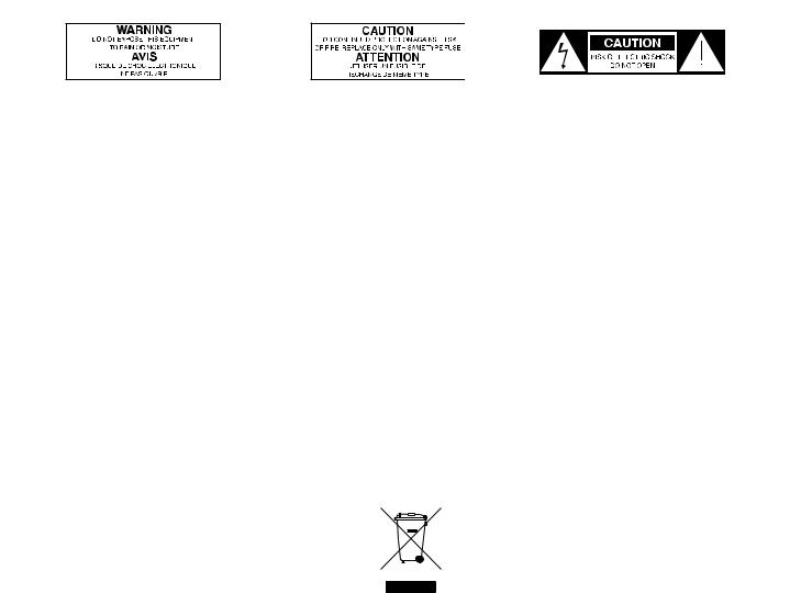
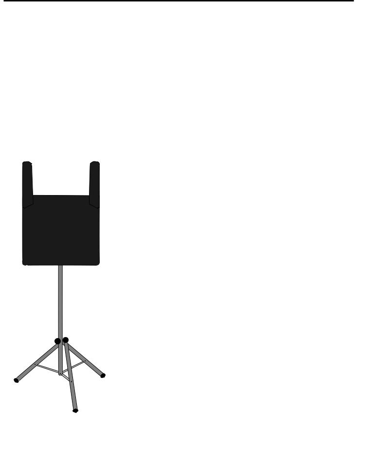
A built-in telescoping handle and locking wheels that make it easier than ever before to transport your audio system.
All Expedition Pro enclosures are lightweight and compact yet exceptionally durable and roadworthy. Injection-molded with Polypropylene, they feature substantial internal bracing to support a nearly 1/2" thick side wall construction, making them strong and rigid enough to allow maximum energy to be delivered to the sound output. In addition, a steel grill and scuff-resistant textured finish makes for a rugged speaker enclosure
that will deliver dependable |
performance in even |
|
the most demanding |
environments. |
|
The low frequency section includes a custom designed Kevlar-impregnated 12" low frequency driver with a
.5" Kapton Former voice coil and 50 ounce barium ferrite magnet for accurate and super-tight bass response.
A high frequency section that delivers clear, sweet top end thanks to its 1" compression driver with a specially designed phenolic diaphragm, along with a phasing plug for linear response and an elliptical wave guide horn design that reduces nearly all sonic diffraction.
A tilt position that allows the Expedition Pro to be used as an onstage wedge monitor.
Integral 1 3/8" pole-mount receptacle and convenient fly points allow the Expedition Pro to be pole-mounted or “flown”using standard PA hardware.
•The XP100 is a passive cabinet that can be used with any power amplifier rated at up to 250 watts into 8 ohms. It requires no power and provides dual Speakon™
and 1/4" connectors that allow multiple XP100s to be |
daisy-chained where |
extended coverage is required. |
|
• The XP200 contains dual power amplifiers and an active crossover. Operating in |
|
a biamped configuration, one power amp drives the low |
frequency section |
with 150 watts of power and the other drives the high |
frequency section with |
50 watts of power. The active crossover uses an advanced Linkwist-Riley constant phase filter that provides a steep rolloff of 24 dB per octave to reduce sonic distortion at the crossover frequencies. Dual balanced XLR connectors allow daisychaining of multiple Expedition Pro enclosures, and a switchable limiter circuit assures a clean output even when you’re pushing the XP200 to maximum levels. In addition, there are three stages of speaker protection, including relay switching for power on and off.
•The XP300 includes all the features of the XP200, and adds a flexible four-channel stereo mixer that provides two monophonic and one stereo mic/line channels
with dual XLR and 1/4" connectors. In addition, separate dual phono connectors allow you to hook up an external cassette or CD player. Each mixer chan-
nel includes two-band equalization and independent volume control, 3
ENGLISH

System Features
ENGLISH
and there’s even built-in digital effects for the addition of six different reverb presets. Balanced left and right XLR outputs allow daisy-chaining of multiple Expedition speakers (with a mono/stereo switch that allows operation in either mode), and aVU meter enables you to continuously monitor output levels. The XP200 and XP300 also include a meter that shows battery level when used with the optional RB 2030 rechargable battery cartridge (see below).
• The top panel of both the XP200 and XP300 provides a prewired compartment that accommodates a variety of Samson wireless systems that offer superior RF and audio performance already proven on stages around the world. Receivers supported include the UM1 or M32 UHF models or the VM1VHF model.
• A wide range of optional accessories, including: the MP 1030 mounting bracket, which allows any Expedition Pro enclosure to be“flown”from the ceiling; the RB 2030 rechargable battery cartridge, which provides up to two hours of power to either the XP200 or XP300 from its dual Lead-Acid GelCel batteries; and theTD30 cassette
recorder, which fits neatly into a |
special |
compartment above the XP300’s mixer to |
|
provide background music and/or to record |
|
meetings or performances. TheTD30 even |
|
includes a pitch control so you can alter |
|
the tempo of the music for applications like |
|
aerobic instruction. |
|
• The EX500 is an active subwoofer that pairs a |
|
massive 500-watt amplifier with a |
heavy- |
duty 15" low frequency driver. It is an ideal
complement to any Expedition Pro enclosure or any loudspeaker system, when the application requires deep, powerful low end response. Its built-in stereo electronic crossover allows the EX500 to operate either in mono or as a common subwoofer in a stereo system. It features an all-steel grill and rigid corners, as well as an integral pole mount.
4
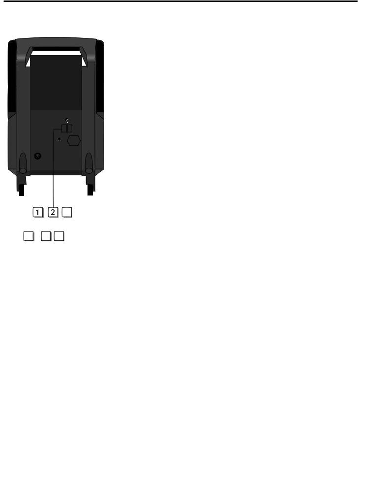
Expedition Pro XP100
GuidedTour
1: 1/4" input - Use this standard 1/4" connector to connect signal from a power |
|
|
amplifier (rated at up to 250 watts into 8 ohms) to the XP100. |
ENGLISH |
|
2: Speakon™ input - Alternatively, you can use this Speakon™ connector to connect |
||
|
||
signal from a power amplifier (rated at up to 250 watts into 8 ohms) to the XP100. |
|
|
3: 1/4" extension - Use this standard 1/4" connector to daisy-chain one XP100 to |
|
|
another. See below for interconnection diagrams. |
|
|
4: Speakon™ extension - Alternatively, you can use this Speakon™ connector to |
|
|
daisy-chain one XP100 to another. See below for interconnection diagrams. |
|
|
Speakon™Wiring |
|
SPEAKON™
 +
+

 -
-
 SPEAKON™
Interconnecting the XP100
Using one XP100: A single mono signal (bus or aux send) is routed from a mixer to a power amplifier. One speaker output of the power amplifier is connected to eitherthe XP100 1/4" input connector (solid line) or Speakon™ input connector (dotted line).
5
Expedition Pro XP100
Using two XP100s in mono: A single mono signal (bus or aux send) is routed from a mixer to a power amplifier. One speaker output of the power amplifier is connected to eitherthe XP100 1/4" input (solid line) or Speakon™ input (dotted line), and a connection is made between eitherthe 1/4" extension to a second XP100’s input (solid line) or between the Speakon™ extension to a second XP100’s Speakon™ input (dotted line).
ENGLISH
Using two XP100s in stereo: A stereo signal (bus or aux send) is routed from a mixer to a power amplifier. The left speaker output of the power amplifier is connected to one XP100 (using eitherthe 1/4" input [solid line] or Speakon™ input [dotted line]), and the right speaker output of the power amplifier is connected to the other XP100 (again using eitherthe 1/4" input [solid line] or Speakon™ input [dotted line]).
6
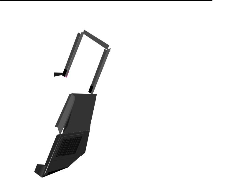
Expedition Pro XP200
GuidedTour
1: Input connector - Use this balanced female XLR connector to route |
line- |
level signal into the XP200. |
|
2: OutputVU meter -This three-segment bar meter shows the XP200 |
output |
level. For optimum signal-to-noise ratio, set theVolume control (see #6 below) so that program material is usually at or around 0VU, with occasional but not steady excursions to the red“+3 dB”segment.
3: Power switch - Use this to turn power to the XP200 on or off.
4:Voltage selector - Make sure this is set correctly for the country you are in before turning on the power to the XP200.
5: BatteryVU meter - If an optional RB 2030 rechargable battery pack is installed, this meter shows how much battery power remains as it is being charged (Power switch off) or depleted (Power switch on).
6:Volume control -This knob sets the level of the XP200’s built-in power amplifiers.
7: Output connector-This balanced male XLR connector carries line-level out-
! |
put signal from the XP200. It is used to send signal to a second XP200 being |
|
|
|
daisy-chained (see interconnection diagram on the following page) or to an |
|
optional EX500 subwoofer. |
|
8: Limiter switch - Use this switch to turn the built-in limiter circuitry on or off. |
|
In order to maximize speaker protection, we recommend that this switch be left |
|
in the“on”position during normal operation. |
|
9: AC input - Connect the supplied heavy-gauge 3-pin“IEC”power cable here. |
Interconnecting the XP200
ENGLISH
Using one XP200: A single mono signal (bus or aux send) is routed from a mixer to the XP200 XLR input.
7
Expedition Pro XP200
Using two XP200s in mono: A single mono signal (bus or aux send) is routed from a mixer to one XP200’s XLR input, and a connection is made between that XP200’s XLR output to a second XP100’s XLR input.
ENGLISH
Using two XP200s in stereo: A stereo signal (bus or aux send) is routed from a mixer, with the left side connected to one XP200’s
XLR input, and the right side connected to the other XP200’s XLR input.
8
Expedition Pro XP300
GuidedTour
1: Equalizer -These controls allow you to shape your sound by boosting or cutting the amount of bass (at 100 Hz) or treble (at 10 kHz) by up to 15 dB. A center detent in each knob indicates no boost or cut (that is, flat response). As each knob is turned clockwise from the 12 o’clock position, the bass or treble is boosted; as it is turned counterclockwise from the 12 o’clock position, the bass or treble is reduced.
2: Reverb send -These knobs determine how much signal is being sent from the channel to the onboard DSP effects processor. As you move the knob clockwise from 0 to 10, more signal is sent. To hear the effect, one of the six presets must be selected using the DSP Effects control (see #10 on the next page). Be careful not to send too much signal to the DSP, or a distorted sound will result.
2
3: Pan/Balance control - In channels 1 and 2, this knob acts as a Pan control, allow-
ing you to place the signal anywhere in the left-right stereo spectrum, while keeping
the overall signal level constant. When the knob is placed at its center (detented)
position, the signal is sent equally to both the left and right outputs. To route a signal
hard left or right, place the pan knob either fully counterclockwise or fully clockwise.
In channel 3/4 (the stereo channel), this knob acts as a Balance control, allowing you
to alter the relative levels of the two input signals. When the knob is placed at its cen-
ter detented position, both signals are at equal strength. When moved left of center, you’ll hear more of the left input signal; when moved right of center, you’ll hear more right input signal.
4: Channel volume control -This knob determines the level of the channel In stereo channel 3/4, this knob simultaneously controls the level of both inputs (the relative levels of the two can be adjusted with the Balance knob, as described in #3 above). In practice, you’ll use the channel volume controls to continuously adjust the levels of the various signals being blended together by the XP300 mixer.
5: Insert (sub) connector -This 1/4" connector brings line-level signal in directly before the XP300 power amplifiers. It is normally used to return signal from an optional EX500 subwoofer.
ENGLISH
5
0 10
|
5 |
|
5 |
|
5 |
0 |
10 |
0 |
10 |
0 |
10 |
REVERB |
REVERB |
REVERB |
|||


 !
!
9

ENGLISH
Expedition Pro XP300
6: Line inputs - Use these 1/4" jacks to connect line-level sources to the XP300. Channels 1 and 2 are mono 1/4" connectors; channel 3/4 uses a stereo (TRS) 1/4" connector, with tip carrying left signal and ring carrying right signal. Stereo devices should always be connected to the stereo channel (channels 3/4). If a wireless receiver is connected to the XP300 via its internal connectors (see page 14 in this manual), its output arrives at channel 2, which can also carry another line-level source connected to its line input, as well as signal from a microphone connected to its mic input. If an optionalTD30 cassette player is installed, its output arrives at channels 3/4, which can also carry another two line-level sources (one connected to its line input and a second connected to the CD inputs [see #15 on the following page]), as well as signal from a microphone connected to its mic input.
7: Mic inputs - Use these XLR jacks to connect microphones to the XP300’s built-in mic preamps. Each channel can carry both one or more line level sources (see #6 above) as well as a mic source.
8:DSP Effects control - Use this to select one of six reverb presets (Small Hall, Medium Hall, Large Hall, Church, Stadium, or Plate). If you don’t want to hear any reverb, set this switch to the“Off”position.
9:Mono/Stereo switch -When using one XP300, set this switch to“Mono”so that the XP300 power amp receives signal from both the left and right output sections. When using multiple Expedition Pro speaker enclosures, set this switch to“Stereo”; the XP300 will then reproduce only signal from the left output section only (that is, signals panned left at the mixer); the Right output can then be used to send
signal from the right output section (that is, signal panned right at the mixer) to a second enclosure. See the interconnection diagrams on pages 10 - 11 for more information.
10: Outputs -The dual XLR connectors carry line-level output signal from the XP300. They are used to send signal to a second XP300 (or XP200) being daisy-chained (see the interconnection diagram on the following page) or to an optional EX500 subwoofer. Note that the signal being output from these connectors is dependent upon the setting of the Mono/Stereo switch (see #9 above). When set to“Stereo,” the Left XLR connector carries left signal only and the Right XLR connector carries right signal only; when set to“Mono,”both the Left and Right connectors carry the same monophonic signal, summed from both the left and right output sections. See the interconnection diagrams on pages 10 - 11 for more information.
11:MainVolume control -This knob determines the final output signal level—you can think of this as being the“master fader.” Signals from all four channels are routed here just before being routed to the XP300’s built-in power amplifiers and Left and Right output jacks (see #10 above).
12:BatteryVU meter - If an optional RB 2030 rechargable battery pack is installed, this meter shows how much battery power remains as it is being charged (Power switch off) or depleted (Power switch on). See #20 on the following page.
13:OutputVU meter -This three-segment bar meter shows the continuous output level of the XP300. For optimum signal-to-noise ratio, try to adjust all channel and mainVolume controls so that program material is usually at or around 0VU, with occasional but not steady excursions to the red“+3 dB”segment.
14:Limiter LED - Lights whenever the built-in limiter is active. If you see this lighting frequently, it means you’re overloading the XP300, so turn down one or more of the Channel volume controls (see #4 on the preceding page) or the mainVolume control (see #11 above).
15:CD inputs - Connect the outputs of a CD or tape player to this set of dual phono jacks. Signal arriving here returns to stereo channel 3/4. If an optionalTD30 cassette player is installed, note that its output also arrives at channels 3/4, in addition to line-level signal arriving at its 1/4"TRS line input (see #6 on the preceding page) and signal from a microphone connected to its mic input (see #7 on the preceding page).
16:AC input - Connect the supplied heavy-gauge 3-pin“IEC”power cable here.
10
Expedition Pro XP300
17: Limiter switch - Use this switch to turn the built-in limiter circuitry on or off. |
In order |
|
to maximize speaker protection, we recommend that this switch be left in the“on”position |
|
|
during normal operation. |
|
|
18:Voltage selector - Make sure this is set correctly for the country you are in before turning |
ENGLISH |
|
on the power to the XP300. |
|
|
19: Gain switch - Sets the line-levelTRS input of channel 3/4 (see #6 on the preceding |
||
page) to either +4 (professional) or -10 (consumer) level. |
|
|
|
|
|
20: Power switch - Use this to turn power to the XP300 on or off. If an optional |
RB 2030 |
|
rechargable battery pack is installed, it will charge when this switch is in the“Off”position. |
|
|
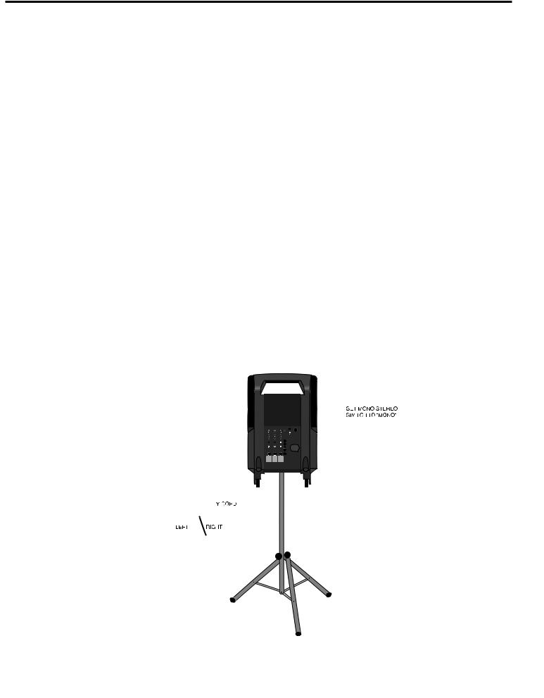
Interconnecting the XP300
Using one XP300: In this example, microphones are connected to the XLR mic inputs of channels 1 and 2, and a stereo keyboard is connected to the stereo 1/4"TRS connector of channel 3/4 (using aY-cord, with the tip carrying the left signal and the ring carrying the right signal).
IMPORTANT NOTE: When using just one XP300, always be sure to set its Mono/Stereo switch to“Mono.”
11
ENGLISH
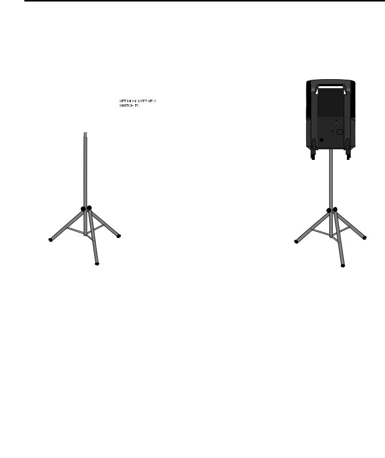
Expedition Pro XP300
Using one XP300 and an XP200 (stereo operation): In this example, microphones are connected to the XLR mic inputs of channels 1 and 2 of an XP300, and a stereo keyboard is connected to the stereo 1/4"TRS connector of channel 3/4 of the XP300 (using aY-cord, with the tip carrying the left signal and the ring carrying the right signal). A connection is then made between the Right output of the XP300 to the XLR input of an XP200. IMPORTANT NOTE: When using the XP300 with additional Expedition Pro enclosures, always be sure to set the XP300 Mono/Stereo switch to“Stereo.”
Using one XP300 and three XP200s (extended range stereo operation): In this example, microphones are connected to the XLR mic inputs of channels 1 and 2 of an XP300, and a stereo keyboard is connected to the stereo 1/4"TRS connector of channel 3/4 of the XP300 (using aY-cord, with the tip carrying the left signal and the ring carrying the right signal). A connection is then made between the Left output of the XP300 to the XLR input of an XP200 (both will then carry the same left channel signal). Finally, a connection is made between the Right output of the XP300 and an XP200, and between that XP200’s XLR output and the XLR input of a third XP200 (both will then carry the same right channel signal). IMPORTANT NOTE: When using the
XP300 with additional Expedition Pro enclosures, always be sure to set the XP300 Mono/Stereo switch to“Stereo.”
12
Positioning and Mounting Instructions
General PositioningTips
•Operating a microphone or turntable in front of a speaker is a sure formula for feedback and/or rumble problems, so always place the Expedition Pro in front of any mics or turntables that are being used.
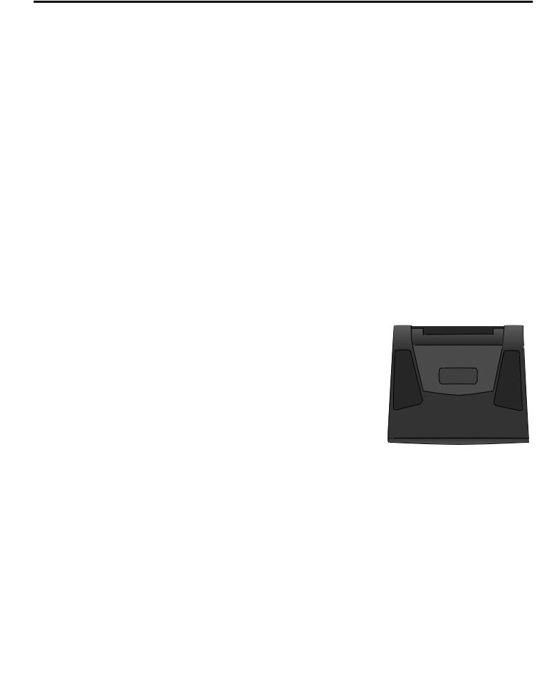
• Use the Expedition Pro upright for all“front-of-house”PA applications; |
use |
it in its tilt-back position only for onstage monitoring. |
|
•Always raise the speakers as high above the audience as is practicable for maximum coverage.
•Use sufficient enclosures for the space you’re in. The larger the space, the more speakers will be required.
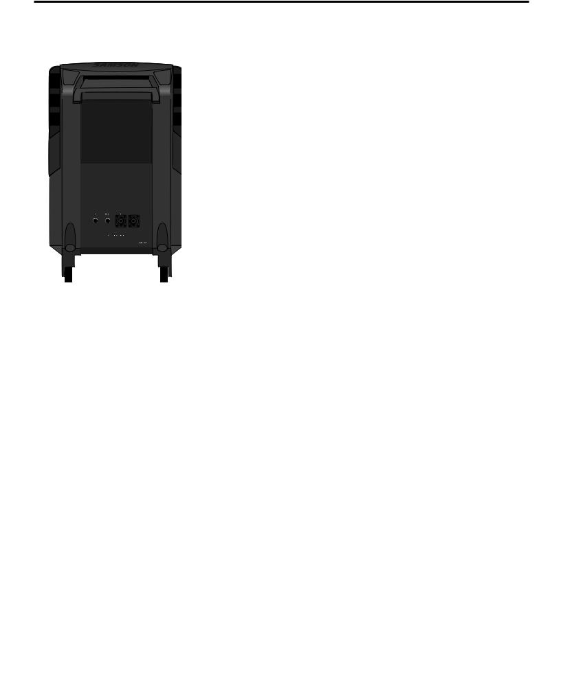
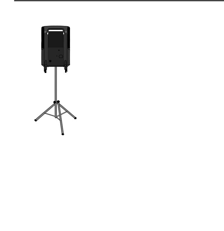
Pole-Mounting
The underside of the Expedition Pro contains a 1-3/8" stand mount socket that allows it to be raised up on any standard speaker pole mounting (such as the Ultimate Support SystemsTS-30 orTS-33 speaker stands). Pole-mounting is generally advisable when you want to maximize the distance that the Expedition Pro covers (sometimes called speaker“throw”).
If you are using an EX500 subwoofer, you can use its integral pole mount to place an XP100, XP200 or XP300 immediately above it, creating a complete column of sound.
ENGLISH
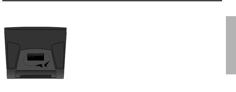
Fly Mounting,Wall Mounting, and Ceiling Mounting
As shown in the illustration below, the top panel of the Expedition Pro contains a number of fly points, located in compartments to the left and right of the wireless receiver compartment. The covers placed over these compartments are simply attached with double-sided sticky tape, so just pull up to remove.
ExpeditionProfly-mountpoints
13
Positioning and Mounting Instructions
ENGLISH
Before fly-mounting, wall-mounting or ceiling-mounting the Expedition Pro, you must first install a Samson MP 1030 mounting bracket to the fly points, as shown in the illustrations on the right
Standard cabling and hardware can then be attached to the MP 1030 mounting bracket in environments where the Expedition Pro needs to be“flown.”
In fixed installations where you wish to mount the Expedition Pro to a ceiling, use the
OmniMount model 100-STMP mount, as shown in the illustration below:
InstallingtheMP1030mounting
bracket(topview)
In fixed installations where you wish to mount the Expedition Pro from a wall, use the
OmniMount model 100-WB mount, as shown in the illustration below:
TopofExpeditionProwithMP1030 mountingbracketinstalled.
14
XP200/XP300wirelesscompartment
(topview)
Expedition Pro Accessories
As shown in the illustration on the left, the top panel of the Expedition Pro XP200 and XP300 provides a prewired compartment that accommodates any of three different Samson wireless receivers: the UM1 or M32 UHF models or theVM1VHF model.
Output signal from a wireless receiver mounted in an XP300 arrives at channel 2 of the onboard mixer.
In addition, a number of accessories are available from your local Samson dealer that allow you to expand the capabilities of your Expedition Pro system. These include:
•The EX500 active subwoofer—the ideal complement to any Expedition Pro enclosure (or to any loudspeaker system, for that matter)—pairs a powerful 500-watt amplifier with a heavy-duty 15" low frequency driver in order to provide deep low end response. A built-in stereo electronic crossover allows the EX500 to operate either in mono or as a common subwoofer in a stereo system. It features an all-
steel grill and rigid corners, as well as an integral 1 3/8" pole-mount receptacle
•The RB 2030 rechargable battery cartridge, which provides up to two hours of power to either the XP200 or XP300 from its dual Lead-Acid GelCel batteries.
•The MP 1030 mounting bracket, which allows any Expedition Pro enclosure to be
“flown”or mounted on the wall or ceiling using standard OmniMount hardware. For more information, see the“Positioning and Mounting the Expedition Pro”section on page 12.
ENGLISH
15

Introduction
FRANÇAIS
Bienvenue pour un tour d'horizon des Samson Expedition Pro — les enceintes audio portables du nouveau millénaire ! D'une polyvalence, d'une mobilité et d'une qualité audio exceptionnelles, ces enceintes sont la solution à vos attentes, qu'il s'agisse d'installer un système de sonorisation principal ou des retours de scène dans un club, un lieu de culte, une salle de spectacle ou bien de disposer d'un système sonore pour des présentations commerciales, pour des DJ itinérants, pour des professeurs de sport ou encore pour une utilisation en extérieur (parcs, plages, marchés). Qui plus est, les enceintes Expedition Pro sont toutes équipées d'une poignée télescopique et de roulettes qui leur permettront de vous suivre partout !
Ce manuel porte sur trois enceintes Samson Expedition Pro différentes.Toutes reprennent le même caisson 2 voies externe léger mais très robuste qui accueille un haut-parleur grave de 30 cm et un haut-parleur aigu à compression adapté de 2,5 cm. L'Expedition Pro XP100 est une enceinte 8 Ohms passive pouvant être relié à n'importe quel amplificateur externe d'au plus 250 Watts. L'Expedition Pro XP200 est une version amplifiée intégrant une bi-amplifica- tion ainsi qu'un filtre actif, des circuits de protection des haut-parleurs et un limiteur interne.
L'Expedition Pro XP300 est une enceinte de sonorisation portable tout-en-un grâce à la présence d'un mélangeur 4 voies et d'effets numériques. Par ailleurs, différentes options sont disponibles, dont un Subwoofer actif 500 Watts (modèle EX500), un accumulateur Lead-Acid rechargeable, ainsi qu'une platine cassette avec variateur de hauteur à loger en face arrière. Il existe même un compartiment précâblé pour accueillir un système sans fil Samson !
Ce manuel vous donne une description détaillée des caractéristiques des trois enceintes de la gamme Expedition Pro, ainsi qu'un tour d'horizon de leurs éléments et leurs procédures de réglage et d'utilisation détaillées. Si vous avez acquis votre Expedition Pro aux Etats-Unis, n'oubliez pas de remplir la carte de garantie fournie et de nous la renvoyer.Vous pourrez ainsi bénéficier de notre service d'assistance technique en ligne et recevoir des renseignements sur les toutes dernières nouveautés Samson. Si vous avez acquis votre Expedition Pro hors des Etats-Unis, vous pouvez prendre connaissance des détails de la garantie auprès de votre dis-
tributeur. N'oubliez pas de non plus de visiter notre site Internet (http://www.samsontech.com) qui regroupe toutes les informations sur toute notre gamme de produits.
NOTE SPÉCIALE : S’il arrive que votre Expedition Pro ait besoin de maintenance, vous devez disposer d’un numéro d’autorisation (Return Authorization) pour nous le renvoyer. Sans ce numéro, l’appareil ne sera pas accepté. S’il a été acheté au Etats-Unis, veuillez appeler le numéro suivant 1-800-372-6766 pour obtenir un numéro d’autorisation avant de renvoyer votre appareil. Si l’appareil n’a pas été acheté aux Etats-Unis, veuillez contacter votre reven-
deur Samson pour obtenir de plus amples informations.Veuillez également conserver le matériel d’emballage original, afin d’y placer l’appareil pour tout transport.
16
 Loading...