


 Loading...
MIXER
AMPLIFIER
SAMSON®
S83 / S63
Introduction 1
S83/S63 Features 2
Guided Tour - S83 4
Overview 4
Channel 5
Main Section 6
Rear Panel 8
Guided Tour - S63 10
Overview 10
Channel 11
Main Section 12
Rear Panel 14
Connecting The S83/S63 - General Suggestions 15 Setting Up and Using the S83/S63 16
Setting the Correct Gain Structure 17
Suggested Performance Applications 20
S83 20
S63 21
Grounding Techniques 22
Using Equalization 23
Using the Effects Sends and Returns 25 Using the Monitor Output 26
Using the Internal Reverb 26
Specifications 27

Introduction
Congratulations on purchasing the Samson S83/S63 Mixer Amplifier! In this manual, we’ll take you on a guided tour through all the features of this powerful and flexible device, and we’ll tell you how to get the most out of the S83/S63. Although designed for easy operation, we suggest you take some time out first to go through these pages so you can fully understand how we’ve implemented a number of unique features.
The S83 and S63 both combine a flexible multi-channel mixer with a clean, powerful amplifier and high-quality spring reverb unit—all in a single compact chassis that mounts easily in any standard 19” rack. Simply plug in your microphones and line-level instruments (such as keyboards, tape decks, CD players, etc.) and connect the unit to any standard speaker system, and you’ve got a complete PA system suitable for use in permanent installations such as churches, conference rooms, small clubs, or similar environments.
The S83 and S63 differ in the number of input channels (the S83 has eight while the S63 has six); the type of equalization (the S83 provides four bands per channel, while the S63 has three); their amplifier power ratings (the S83 delivers 300 watts into 4 ohms, while the S63 delivers 210 watts into 4 ohms); the number of Effects returns (the S83 has four while the S63 has two) and the presence or absence of a master metering section, peak LEDs, and headphone preamplifier (the S83 has all of these while the S63 does not). Both units include a 10-band graphic master equalizer, a master level control, phantom power, two Effects sends, and a Monitor output as well as dedicated tape/CD input.
In these pages, we’ll begin with an overview of the main S83/S63 features, followed by a guided tour of both units’ front and rear panels. Then we’ll describe the various input and output connections (including wiring diagrams) and tell you in detail how to set up your S83/S63 as well as showing you how best to use the unit in live performance. Finally, we’ll cover a number of specific topics (such as grounding techniques, using equalization, and using the effects sends and returns) and then wrap things up with full specifications.
Oh, and one last thing—don’t forget to fill out and mail in the enclosed warrantee card! This will enable you to receive online technical support and will allow us to send you updated information about other Samson products in the future.
1

S83/S63 Features
The Samson S83/S63 utilizes state-of-the-art technology in integrated mixer/amplifier design. Here are some of its main features:
•Standard 19” rack-mount design (taking just four rack spaces) allows the S83 and S63 to be easily integrated into any setup.
•Multiple channels (eight in the S83; six in the S63) and mic and line inputs for each channel allow you to blend together a variety of source signals, including dynamic or condenser microphones, keyboards, CD/tape players, etc. Standard XLR mic connectors (for microphone inputs) and electronically
balanced 1/4” jacks (for line-level inputs) are provided for each channel; in addition, there is a dedicated CD/Tape input that provides dual phono (RCA) jacks.
•Power to spare—both units include a clean, high-quality amplifier, delivering 300 watts (in the case of the S83) or 210 watts (in the case of the S63) into four ohms. Any standard speaker cabinets (two, four, eight, or sixteen ohms) can be connected to the rear-panel 1/4” speaker output jacks.
•A built-in three-spring reverb unit allows you to add reverberation effects to your vocals or instruments without having to use an expensive external signal processor. A front-panel reverb master volume control allows you to precisely define the amount of reverb to be added to the signal.
•Each channel provides independent equalization controls (four-band in the S83; three-band in the S63), enabling you to shape the sound of your input signal sources. In addition, a ten-band graphic master equalizer allows you to “tune” the output of the S83/S63 to the particular room environment you are in. This can be particularly useful for eliminating ringing or feedback problems.
•In the S83, Peak LEDs for each channel show you at a glance when an input signal is on the verge of overloading. In the S63, a master Peak LED shows you at a glance when the internal amplifier is overloading. In both units, other front-panel LEDs show the current status of the amplifier’s protection relay circuitry and whether or not phantom power is being applied.
•Independent input Trim controls for each channel that allows you to precisely set the correct input gain.
•Two Effects sends per channel (one pre-fade and the other post-fade) allow you to route multiple signals to the internal reverb unit or to external signal processors. The pre-fade send (Effects send 1) can be used as a Monitor control, allowing you to set up an onstage monitor mix that is independent of the main house mix. A separate Monitor level control is provided on the front panel.
•In the S83, four Effects returns give you the ability to blend in the return signal from external signal processors or other line-level devices without having to utilize input channels. Two front-panel Effects return level controls (one for Effects returns 1-2 and the other for Effects returns 3-4) allow you to bring in stereo signals, which are then automatically mixed together in mono. In the S63, two Effects returns are provided, with a single front-panel control for the two.
2

S83/S63 Features
•A phantom power switch enables you to use the S83 and S63 with highquality condenser microphones. When turned on, 48 volts of phantom power is provided to the mic connectors of all input channels.
•Protection relay circuitry prevents “thumps” when powering on or off. This means that you can use the S83/S63 with a single power strip into which other audio devices are connected, without danger of damage to connected speakers.
•A rear-panel amplifier input allows you to bring external signals from other mixers or audio devices into the S83/S63 power amplifier.
•A rear-panel preamplifier output allows you to connect the S83/S63 to external power amplifiers when higher power ratings are required and/or when additional amplifier feeds are necessary.
•In the S83, a built-in headphone amplifier, with a front-panel 1/4” stereo connector and dedicated level control allows you to monitor your main mix.
•In the S83, a convenient front-panel meter allows you to see at a glance the continuous output signal level.
We’ll elaborate on many of these terms and features later in this manual. Now it’s time to take a guided tour of the units, starting with the S83.
3

Guided Tour - S83 Overview
The following illustration shows an overview of the front panel of the S83:
|
CHANNEL 1 |
|
CHANNEL 2 |
|
CHANNEL 3 |
|
CHANNEL 4 |
|
CHANNEL 5 |
|
CHANNEL 6 |
|
CHANNEL 7 |
|
CHANNEL 8 |
|
|
|
|
|
|
|
|
|
|
|
||||||||||||||||
|
|
|
PEAK |
|
|
|
PEAK |
|
|
|
PEAK |
|
|
|
PEAK |
|
|
|
PEAK |
|
|
|
PEAK |
|
|
|
PEAK |
|
|
|
PEAK |
|
|
S8 MIXER AMPLIFIER |
|
|
||||||
|
0 |
|
|
|
0 |
|
|
|
0 |
|
|
|
0 |
|
|
|
0 |
|
|
|
0 |
|
|
|
0 |
|
|
|
0 |
|
|
|
|
|
|
|||||||
−∞ |
+15 |
|
|
−∞ |
+15 |
|
|
−∞ |
+15 |
|
|
−∞ |
+15 |
|
|
−∞ |
+15 |
|
|
−∞ |
+15 |
|
|
−∞ |
+15 |
|
|
−∞ |
+15 |
|
|
|
|
8 CHANNEL MIXER 300 WATT AMPLIFIER |
|
|
||||||
|
LEVEL |
|
|
|
LEVEL |
|
|
|
LEVEL |
|
|
|
LEVEL |
|
|
|
LEVEL |
|
|
|
LEVEL |
|
|
|
LEVEL |
|
|
|
LEVEL |
|
|
|
|
|
|
|
|
|
|
|
|
|
|
|
|
0 |
|
|
|
0 |
|
|
|
0 |
|
|
|
0 |
|
|
|
0 |
|
|
|
0 |
|
|
|
0 |
|
|
|
0 |
|
|
-18 |
-12 |
-8 -5 |
-3 |
0 |
+2 |
|
|
|
|
|
|
|
|
|
|
|
|
|
|
|
|
|
|
|
|
|
|
|
|
|
|
|
|
|
|
|
|
|
|
|
|
|
|
||||||||
|
0 |
|
|
|
0 |
|
|
|
0 |
|
|
|
0 |
|
|
|
0 |
|
|
|
0 |
|
|
|
0 |
|
|
|
0 |
|
|
|
PHANTOM |
PROTECTION |
POWER |
|
|
|||||
|
|
|
|
|
|
|
|
|
|
|
|
|
|
|
|
|
|
|
|
|
|
|
|
|
|
|
|
|
|
|
|
|
|
|
||||||||
−∞ |
+10 |
-15 |
+15 |
−∞ |
+10 |
-15 |
+15 |
−∞ |
+10 |
-15 |
+15 |
−∞ |
+10 |
-15 |
+15 |
−∞ |
+10 |
-15 |
+15 |
−∞ |
+10 |
-15 |
+15 |
−∞ |
+10 |
-15 |
+15 |
−∞ |
+10 |
-15 |
+15 |
|
|
|
|
|
|
|
|
|
|
|
EFF1 MON |
|
HIGH |
EFF1 MON |
|
HIGH |
EFF1 MON |
|
HIGH |
EFF1 MON |
|
HIGH |
EFF1 MON |
|
HIGH |
EFF1 MON |
|
HIGH |
EFF1 MON |
|
HIGH |
EFF1 MON |
|
HIGH |
30Hz |
64Hz |
125Hz |
|
250Hz |
500Hz |
1K |
2K |
3K |
5K |
10K |
||||||||
|
|
|
0 |
|
|
|
0 |
|
|
|
|
|
|
|
|
|
|
|
0 |
|
|
|
|
|
|
|
0 |
|
|
|
0 |
|
||||||||||
|
|
|
|
|
|
|
|
|
0 |
|
|
|
0 |
|
|
|
|
|
|
0 |
|
|
|
|
|
|
|
|
|
|
|
|
|
|
|
|
|
|||||
|
0 |
|
|
|
0 |
|
|
|
0 |
|
|
|
0 |
|
|
|
0 |
|
|
|
0 |
|
|
|
0 |
|
|
|
0 |
|
|
|
|
|
|
|
|
|
|
|
|
+15dB |
−∞ |
+10 |
-12 |
+12 |
−∞ |
+10 |
-12 |
+12 |
−∞ |
+10 |
-12 |
+12 |
−∞ |
+10 |
-12 |
+12 |
−∞ |
+10 |
-12 |
+12 |
−∞ |
+10 |
-12 |
+12 |
−∞ |
+10 |
-12 |
+12 |
−∞ |
+10 |
-12 |
+12 |
|
|
|
|
|
|
|
|
|
|
0dB |
EFF2 REV |
|
2.5K |
EFF2 REV |
|
2.5K |
EFF2 REV |
|
2.5K |
EFF2 REV |
|
2.5K |
EFF2 REV |
|
2.5K |
EFF2 REV |
|
2.5K |
EFF2 REV |
|
2.5K |
EFF2 REV |
|
2.5K |
|
|
|
|
|
|
|
|
|
|
|||||||||
|
10 |
|
0 |
|
10 |
|
0 |
|
10 |
|
0 |
|
10 |
|
0 |
|
10 |
|
0 |
|
10 |
|
0 |
|
10 |
|
0 |
|
10 |
|
0 |
|
|
|
|
|
|
|
|
|
|
|
0 |
|
|
|
0 |
|
|
|
0 |
|
|
|
0 |
|
|
|
0 |
|
|
|
0 |
|
|
|
0 |
|
|
|
0 |
|
|
|
|
|
|
|
|
|
|
|
|
|
-15dB |
|
|
|
|
|
|
|
|
|
|
|
|
|
|
|
|
|
|
|
|
|
|
-12 |
+12 |
|
|
|
|
|
|
|
|
|
|
|
||||||||
+4 |
-40 |
-12 |
+12 |
+4 |
-40 |
-12 |
+12 |
+4 |
-40 |
-12 |
+12 |
+4 |
-40 |
-12 |
+12 |
+4 |
-40 |
-12 |
+12 |
+4 |
-40 |
-12 |
+12 |
+4 |
-40 |
-12 |
+12 |
+4 |
-40 |
|
|
|
|
|
|
|
|
|
|
|
||
|
TRIM |
|
500Hz |
|
TRIM |
|
500Hz |
|
TRIM |
|
500Hz |
|
TRIM |
|
500Hz |
|
TRIM |
|
500Hz |
|
TRIM |
|
500Hz |
|
TRIM |
|
500Hz |
|
TRIM |
|
500Hz |
30Hz |
64Hz |
125Hz |
|
250Hz |
500Hz |
1K |
2K |
3K |
5K |
10K |
|
|
|
0 |
|
|
|
0 |
|
|
|
0 |
|
|
|
0 |
|
|
|
0 |
|
|
|
0 |
|
|
|
0 |
|
|
|
0 |
|
|
|
|
|
|
|
|
|
|
|
|
|
|
|
|
|
|
|
|
|
|
|
|
|
|
|
|
|
|
|
|
|
|
|
|
|
|
|
|
|
|
|
|
0 |
|
|
|
0 |
|
0 |
|
|
|
|
|
-15 |
+15 |
|
|
-15 |
+15 |
|
|
-15 |
+15 |
|
|
-15 |
+15 |
|
|
-15 |
+15 |
|
|
-15 |
+15 |
|
|
-15 |
+15 |
|
|
-15 |
+15 |
−∞ |
+10 |
−∞ |
|
+10 |
−∞ |
+10 |
|
0 |
10 |
|
|
|
|
LOW |
LINE |
|
LOW |
LINE |
|
LOW |
|
|
|
LOW |
LINE |
|
LOW |
|
|
|
LOW |
|
|
|
LOW |
LINE |
|
LOW |
MAIN LEVEL |
RETURN 1-2 |
RETURN 3-4 |
|
HEADPHONES |
||||||||||
LINE |
|
|
|
|
|
|
LINE |
|
|
|
|
LINE |
|
|
LINE |
|
|
|
|
|
||||||||||||||||||||||
|
|
|
|
|
|
|
|
|
|
|
|
|
|
|
|
|
|
|
|
|
|
|
|
|
|
|
|
|
|
|
|
|
|
|
|
|
|
|
0 |
|
|
|
|
|
|
|
|
|
|
|
|
|
|
|
|
|
|
|
|
|
|
|
|
|
|
|
|
|
|
|
|
|
|
|
|
|
|
0 |
10 |
−∞ |
+10 |
|
|
|
|
|
|
|
|
|
|
|
|
|
|
|
|
|
|
|
|
|
|
|
|
|
|
|
|
|
|
|
|
|
|
|
|
|
|
|
|
|
|
|
|
|
|
|
|
|
|
MIC |
|
|
|
MIC |
|
|
|
MIC |
|
|
|
MIC |
|
|
|
MIC |
|
|
|
MIC |
|
|
|
MIC |
|
|
|
MIC |
PHANTOM |
|
REVERB |
MONITOR |
|
|
|
||||
|
|
|
|
|
|
|
|
|
|
|
|
|
|
|
|
|
|
|
|
|
|
|
|
|
|
|
|
|
|
|
|
|
|
|
||||||||
Channels Main Section
4
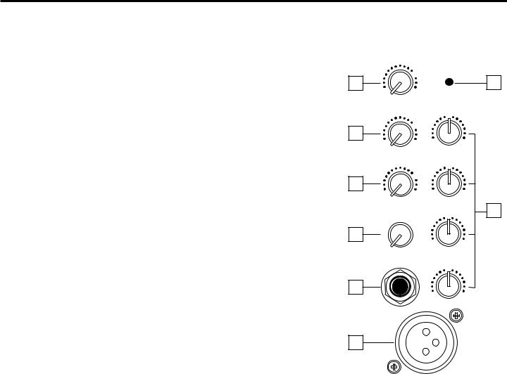
Guided Tour - S83 Channel
1:Level (white) - This knob determines the final signal level being sent by a channel to the main speaker outputs as well as to Effect send 1 (see #2 below). In practice, this will be used to adjust the levels of the various signals being blended together by the S83. The “0” position indicates unity gain (no
level attenuation or boost). Moving the knob counterclockwise from “0” (towards the “∞ ” position) causes the signal to be attenuated (when fully counterclockwise, the signal is attenuated infinitely— in other words, there is no sound). Moving it clockwise from the “0” position (towards the “+15” position) causes the signal to be boosted by as much as 15 db. For best signal- to-noise ratio, all channel level controls should be kept at or near the 0 level.
2:Effect 1 / Monitor (gray) - This knob allows you to send signal from one or more channels to the S83’s Monitor output or to an external signal processor connected to the Effect Send 1 output jack on the rear panel. This effects send is pre-fade; that is, the level of the signal is determined solely by the channel’s input trim, and is unaffected by its EQ settings and the position of its level control. At the 0 position, the signal is routed with unity gain (that is, no boost or attenuation). As each Effect 1 / Monitor knob is turned clockwise from the 0 position, the signal is boosted; as it is turned counterclockwise from the 0 position, the signal is attenuated.
3:Effect 2 / Reverb (gray) - This knob allows you to send signal from one or more channels to the S83’s internal reverb unit or to an external signal processor connected to the Effect Send 2 output jack on the rear panel. This effects send is post-fade; that is, the level of the signal is determined by the channel’s input trim, its EQ settings, and the position of its level control. At the 0 position, the signal is routed with unity gain (that is, no boost or attenuation). As each Effect 2 / Reverb knob is turned clockwise from the 0 position, the signal is boosted; as it is turned counterclockwise from the 0 position, the signal is attenuated.
|
|
|
|
PEAK |
|
1 |
|
0 |
|
|
5 |
|
+15 |
|
|
||
−∞ |
|
|
|
|
|
|
|
LEVEL |
|
|
|
|
|
|
|
0 |
|
2 |
|
0 |
|
|
|
|
|
-15 |
+15 |
|
|
−∞ |
|
+10 |
|
||
|
EFF1 MON |
|
HIGH |
|
|
|
|
|
|
0 |
|
3 |
|
0 |
|
|
|
|
|
|
|
|
|
−∞ |
|
+10 |
-12 |
+12 |
|
|
EFF2 REV |
|
2.5K |
6 |
|
|
|
10 |
|
0 |
|
|
|
|
|
||
4 |
0 |
|
-12 |
+12 |
|
+4 |
-40 |
|
|||
|
|
TRIM |
500Hz |
|
|
|
|
|
|
0 |
|
7 |
|
|
-15 |
+15 |
|
|
|
|
|
||
|
|
|
|
LOW |
|
LINE |
|
|
|
||
8
MIC
4:Input trim (black) - This knob determines the input level of the connected mic or line signal. Continuously adjustable from +4 db to -40 db, the input trim is at unity gain (no boost or attenuation) when set to the “0” position. The input signal is boosted when the trim is turned to the right of “0” and attenuated when turned to the left of “0.”
5:Peak LED (red) - This warning light indicates an overload situation. It lights whenever a channel’s signal is 5 db short of clipping. To stop it from lighting (and to eliminate the accompanying sonic distortion), turn down the channel’s Input Trim knob (see #4 above) or reduce the amount of equalization boost.
6:Equalizer (blue) - These knobs determine the amount of boost or attenuation in each of four frequency areas. The high and low frequency knobs provide 15 db of cut or boost at 10 kHz and 80 Hz, respectively, with shelving-type control. The high mid and low mid frequency knobs provide 12 db of cut or boost at 2.5 kHz and 500 Hz, respectively, with a bell (peaking) curve. A center detent in each knob (at the 12 o’clock position) indicates no boost or attenuation (that is, flat response). As each knob is turned clockwise from the center detent position, the frequency area is boosted; as it is turned counterclockwise from the center detent position, the frequency area is attenuated.
7:Line input connector - Connect line-level sources (such as synthesizers, drum machines, CD players, tape decks, or effects processors) to any of the S83’s eight channels using this electronically balanced 1/4” jack (balanced or unbalanced signals can be accepted here). WARNING: Do not connect a channel’s line input if you already have something connected to its microphone input; each channel is designed to accept only one source or the other.
8:Mic input connector - Connect a microphone to any of the S83’s eight channels using this standard XLR jack. This jack is intended to accept signal from low-level, low-impedance mics but can also be used to accept signal from other sources (such as direct injection boxes) if the Input Trim control is turned down. WARNING: Do not turn the S83’s Phantom power on if signal sources other than microphones are connected to any of these inputs. Also, do not connect a channel’s microphone input if you already have something connected to its line input; each channel is designed to accept only one source or the other.
5
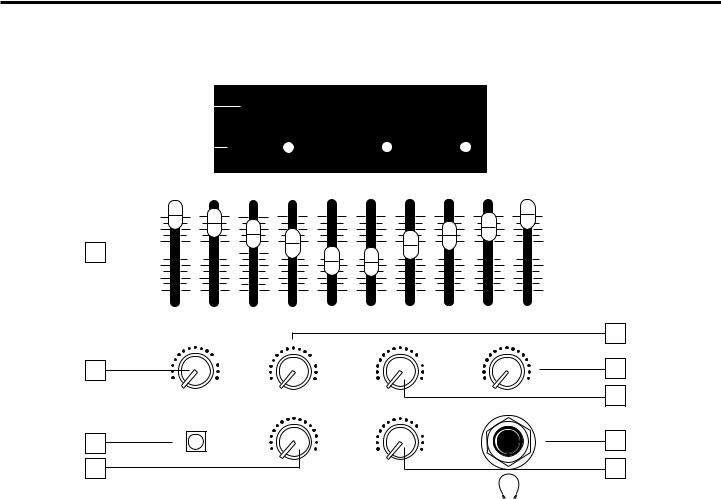
Guided Tour - S83 Main Section
8 CHANNEL MIXER 300 WATT AMPLIFIER
1 |
|
|
|
|
|
|
|
|
|
|
|
|
|
|
|
|
|
|
|
|
|
|
|
|
|
|
|
|
|
|
|
|
|
|
|
|
|
|
|
||
|
|
|
|
|
|
|
|
|
|
|
|
|
|
|
|
|
|
|
|
|
|
|
|
|
|
-18 |
|
-12 |
|
-8 -5 |
-3 |
0 |
+2 |
|
|
||||||
|
|
|
|
|
|
|
|
|
||||||||||||
|
|
|
|
|
|
|
|
|
|
|||||||||||
2 |
|
|
|
PHANTOM |
PROTECTION |
|
POWER |
|
|
|||||||||||
|
|
|
|
|
|
|||||||||||||||
|
30Hz |
64Hz |
125Hz |
250Hz |
500Hz |
1K |
2K |
3K |
5K |
10K |
||||||||||
|
||||||||||||||||||||
+15dB
3 


 0dB
0dB
|
|
|
|
|
|
|
|
|
|
-15dB |
|
30Hz |
64Hz |
125Hz |
250Hz |
500Hz |
1K |
2K |
3K |
5K |
10K |
|
|
|
|
|
|
|
|
|
|
6 |
4 |
|
0 |
|
|
0 |
|
0 |
|
|
10 |
|
|
|
|
|
|
|
|
|
||
|
−∞ |
+10 |
−∞ |
+10 |
−∞ |
+10 |
|
0 |
10 |
|
|
MAIN LEVEL |
RETURN 1-2 |
RETURN 3-4 |
|
|
7 |
||||
|
|
HEADPHONES |
||||||||
5 |
|
|
|
|
|
|
0 |
|
|
11 |
|
|
0 |
10 |
|
+10 |
|
|
|||
8 |
|
|
−∞ |
|
|
9 |
||||
|
|
|
|
|
|
|
|
|||
PHANTOM |
REVERB |
MONITOR |
|
|
||||||
|
|
|
|
|||||||
1:Meter - This seven-segment bar meter shows the continuous output level of the S83. For optimum signal-to-noise ratio, try to adjust all levels (channel and main) so that program material is usually at or around 0 VU, with occasional but not steady excursions to the +2 segment. See the “Setting Up and Using the S83/S63” section in this manual for more information.
2:Meter LEDs - These show the status of various conditions within the S83. The leftmost LED (labeled “Phantom”) lights steadily when Phantom power is being supplied to all mic inputs (see #5 below). The center LED (labeled “Protection”) lights for approximately five seconds whenever the S83 is powered on and fades slowly when the unit is powered off. It indicates the activity of the built-in protection relay circuitry during which time 0 volts DC are provided to all connected speakers, thus preventing any “thump.” The rightmost LED (labeled “Power”) lights steadily whenever the S83 is powered on.
3:Ten-Band Graphic Master EQ - These sliders allow you to add ±15 db of boost or attenuation to ten different frequency areas, affecting the main output signal of the S83. When a slider is at its center detented (“0 db”) position, the selected frequency area is unaffected (it is said to be flat). When a slider is moved up (above the “0 db” position, towards the “+15 db” position), the selected frequency area is boosted, and when it is moved down (below the “0 db” position, towards the “-15 db” position), the selected frequency area is being attenuated. For more information, see the “Using Equalization” section in this manual.
4:Main Level (white) - This knob determines the final signal level sent to the speaker output jacks on the rear panel. At the fully counterclockwise (“∞ ”) position, the signal is infinitely attenuated— that is, there is no sound. At the “0” position, the mixer is at unity gain and is providing no attenuation or boost to the
6

Guided Tour - S83 Main Section
output signal. At the fully clockwise (“+10”) position, approximately 10 db of gain is being added by the mixer to the output signal. For more information, see the “Setting Up and Using the S83/S63” section in this manual.
5:Phantom switch - When this switch is pressed in, the S83 delivers 48 volts of phantom power to pins 2 and 3 of all XLR microphone connectors in all eight channels. WARNING: Only use this switch with the S83 powered down. Before turning phantom power on, be sure to disconnect all non-microphone signal sources (such as direct injection boxes) from the XLR mic jacks. Although phantom power will have no adverse affect on connected dynamic microphones, it should be used only when one or more condenser microphones are connected to the S83. Refer to the owners manual of your microphone to determine whether or not it requires 48 volts phantom power—we cannot assume responsibility if you damage a mic by incorrectly applying S83 phantom power. If you’re not completely certain that one or more connected mics require 48 volts phantom power, leave this switch off (its out position).
6:Return 1-2 Level (green) - This knob determines the input level of signal arriving via Effects returns 1 and 2 (mixed together in mono). This signal is at unity gain (no boost or attenuation) when the knob set to the 0 position and is boosted when the knob is turned to the right of 0 and attenuated when turned to the left of 0. For information on how to properly set this, see the sections in this manual entitled “Setting Up and Using the S83/S63” and “Using the Effects Sends and Returns.”
7:Return 3-4 Level (green) - This knob determines the input level of signal arriving via Effects returns 3 and 4 (mixed together in mono). This signal is at unity gain (no boost or attenuation) when the knob set to the 0 position and is boosted when the knob is turned to the right of 0 and attenuated when turned to the left of 0. For information on how to properly set this, see the sections in this manual entitled “Setting Up and Using the S83/S63” and “Using the Effects Sends and Returns.”
8:Reverb Level (green) - This knob determines the level of the return signal from the internal reverb unit. The amount of incoming reverb signal is increased as the knob is turned clockwise. For more information, see the “Using the Effects Sends and Returns” section in this manual.
9:Monitor Level (green) - This knob determines the overall level of the signal being output from the rear panel Monitor jack. The amount of signal sent is increased as the knob is turned clockwise. For more information, see the “Using the Effects Sends and Returns” section in this manual.
10:Headphone Level (black) - This knob sets the level of the signal sent to the headphone jack. WARNING: To avoid possible damage to connected headphones (or, worse yet, to your ears!), always turn this all the way off (to the fully counterclockwise “0” position) before plugging in a pair of headphones— then raise the level slowly while listening. The Headphone Level has no effect on the final output level.
11:Headphone jack - Connect any standard stereo headphones to this jack (via a standard 1/4” TRS plug) for private monitoring of the final output signal. NOTE: The S83 main speaker outputs are not muted when headphones are
inserted into the Headphone jack— to monitor your main mix in privacy, it is necessary to set the Main Level control to its fully counterclockwise (“∞ ”) position. The built-in S83 headphone amplifier delivers 20 mW into 8 ohms.
7
Loading...