


®
Two-way Active Studio Reference Monitor
A U D I O
MONITORS REFERENCE STUDIO

Safety Instructions/Consignes de sécurité/Sicherheitsvorkehrungen/Instrucciones de seguridad
WARNING: To reduce the risk of fire or electric shock, do not expose this unit to rain or moisture. To reduce the hazard of electrical shock, do not remove cover or back. No user serviceable parts inside. Please refer all servicing to qualified personnel.The lightning flash with an arrowhead symbol within an equilateral triangle, is intended to alert the user to the presence of uninsulated "dangerous voltage" within the products enclosure that may be of sufficient magnitude to constitute a risk of electric shock to persons. The exclamation point within an equilateral triangle is intended to alert the user to the presence of important operating and maintenance (servicing) instructions in the literature accompanying the product.
Important Safety Instructions
1.Please read all instructions before operating the unit.
2.Keep these instructions for future reference.
3.Please heed all safety warnings.
4.Follow manufacturers instructions.
5.Do not use this unit near water or moisture.
6.Clean only with a damp cloth.
7.Do not block any of the ventilation openings. Install in accordance with the manufacturers instructions.
8.Do not install near any heat sources such as radiators, heat registers, stoves, or other apparatus (including amplifiers) that produce heat.
9.Do not defeat the safety purpose of the polarized or grounding-type plug. A polarized plug has two blades with one wider than the other. A grounding type plug has two blades and a third grounding prong. The wide blade or third prong is provided for your safety. When the provided plug does not fit your outlet, consult an electrician for replacement of the obsolete outlet.
10.Protect the power cord from being walked on and pinched particularly at plugs, convenience receptacles and at the point at which they exit from the unit.
11.Unplug this unit during lightning storms or when unused for long periods of time.
12.Refer all servicing to qualified personnel. Servicing is required when the unit has been damaged in any way, such as power supply cord or plug damage, or if liquid has been spilled or objects have fallen into the unit, the unit has been exposed to rain or moisture, does not operate normally, or has been dropped.
ACHTUNG: Um die Gefahr eines Brandes oder Stromschlags zu verringern, sollten Sie dieses Gerät weder Regen noch Feuchtigkeit aussetzen.Um die Gefahr eines
Stromschlags zu verringern, sollten Sie weder Deckel noch Rückwand des Geräts entfernen. Im Innern befinden sich keine Teile, die vom Anwender gewartet werden können. Überlassen Sie die Wartung qualifiziertem Fachpersonal.Der Blitz mit Pfeilspitze im gleichseitigen Dreieck soll den Anwender vor nichtisolierter“gefährlicher Spannung” im Geräteinnern warnen. Diese Spannung kann so hoch sein, dass die Gefahr eines Stromschlags besteht. Das Ausrufezeichen im gleichseitigen Dreieck soll den Anwender auf wichtige Bedienungsund Wartungsanleitungen aufmerksam machen, die im mitgelieferten Informationsmaterial näher beschrieben werden.
Wichtige Sicherheitsvorkehrungen
1.Lesen Sie alle Anleitungen, bevor Sie das Gerät in Betrieb nehmen.
2.Bewahren Sie diese Anleitungen für den späteren Gebrauch gut auf.
3.Bitte treffen Sie alle beschriebenen Sicherheitsvorkehrungen.
4.Befolgen Sie die Anleitungen des Herstellers.
5.Benutzen Sie das Gerät nicht in der Nähe von Wasser oder Feuchtigkeit.
6.Verwenden Sie zur Reinigung des Geräts nur ein feuchtes Tuch.
7.Blockieren Sie keine Belüftungsöffnungen. Nehmen Sie den Einbau des Geräts nur entsprechend den Anweisungen des Herstellers vor.
8.Bauen Sie das Gerät nicht in der Nähe von Wärmequellen wie Heizkörpern,
Wärmeklappen, Öfen oder anderen Geräten (inklusive Verstärkern) ein, die Hitze erzeugen.
9.Setzen Sie die Sicherheitsfunktion des polarisierten oder geerdeten Steckers nicht außer Kraft. Ein polarisierter Stecker hat zwei flache, unterschiedlich breite Pole. Ein geerdeter Stecker hat zwei flache Pole und einen dritten Erdungsstift. Der breitere Pol oder der dritte Stift dient Ihrer Sicherheit. Wenn der vorhandene Stecker nicht in
Ihre Steckdose passt, lassen Sie die veraltete Steckdose von einem Elektriker ersetzen.
10.Schützen Sie das Netzkabel dahingehend, dass niemand darüber laufen und es nicht geknickt werden kann. Achten Sie hierbei besonders auf Netzstecker, Mehrfachsteckdosen und den Kabelanschluss am Gerät.
11.Ziehen Sie den Netzstecker des Geräts bei Gewittern oder längeren Betriebspausen aus der Steckdose.
12.Überlassen Sie die Wartung qualifiziertem Fachpersonal. Eine Wartung ist notwendig, wenn das Gerät auf irgendeine Weise, beispielsweise am Kabel oder
Netzstecker beschädigt wurde, oder wenn Flüssigkeiten oder Objekte in das Gerät gelangt sind, es Regen oder Feuchtigkeit ausgesetzt war, nicht mehr wie gewohnt betrieben werden kann oder fallen gelassen wurde.
ATTENTION: Pour éviter tout risque d’électrocution ou d’incendie, ne pas exposer cet appareil à la pluie ou à l’humidité. Pourévitertoutrisqued’électrocution,nepas ôterlecouvercleouledosduboîtier. Cet appareil ne contient aucune pièce remplaçable par l'utilisateur. Confiez toutes les réparations à un personnel qualifié. Le signe avec un éclair dans un triangle prévient l’utilisateur de la présence d’une
tension dangereuse et non isolée dans l’appareil. Cette tension constitue un risque d’électrocution. Le signe avec un point d’exclamation dans un triangle prévient l’utilisateur d’instructions importantes relatives à l’utilisation et à la maintenance du produit.
Consignes de sécurité importantes
1.Veuillez lire toutes les instructions avant d’utiliser l’appareil.
2.Conserver ces instructions pour toute lecture ultérieure.
3.Lisez avec attention toutes les consignes de sécurité.
4.Suivez les instructions du fabricant.
5.Ne pas utiliser cet appareil près d’une source liquide ou dans un lieu humide.
6.Nettoyez l’appareil uniquement avec un tissu humide.
7.Veillez à ne pas obstruer les fentes prévues pour la ventilation de l’appareil. Installez l’appareil selon les instructions du fabricant.
8.Ne pas installer près d’une source de chaleur (radiateurs, etc.) ou de tout équipement susceptible de générer de la chaleur (amplificateurs de puissance par exemple).
9.Ne pas retirer la terre du cordon secteur ou de la prise murale. Les fiches canadiennes avec polarisation (avec une lame plus large) ne doivent pas être modifiées. Si votre prise murale ne correspond pas au modèle fourni, consultez votre électricien.
10.Protégez le cordon secteur contre tous les dommages possibles (pincement, tension, torsion,, etc.). Veillez à ce que le cordon secteur soit libre, en particulier à sa sortie du boîtier.
11.Déconnectez l’appareil du secteur en présence d’orage ou lors de périodes d’inutilisation prolongées.
12.Consultez un service de réparation qualifié pour tout dysfonctionnement (dommage sur le cordon secteur, baisse de performances, exposition à la pluie, projection liquide dans l’appareil, introduction d’un objet dans le boîtier, etc.).
PRECAUCION: Para reducir el riesgo de incendios o descargas, no permita que este aparato quede expuesto a la lluvia o la humedad. Para reducir el riesgo de descarga eléctrica, nunca quite la tapa ni el chasis. Dentro del aparato no hay piezas susceptibles de ser reparadas por el usuario. Dirija cualquier reparación al servicio técnico oficial. El símbolo del relámpago dentro del triángulo equilátero pretende advertir al usuario de la presencia de“voltajes peligrosos”no aislados dentro de la carcasa del producto, que pueden ser de la magnitud suficiente como para constituir un riesgo de descarga eléctrica a las personas. El símbolo de exclamación dentro del triángulo equilátero quiere advertirle de la existencia de importantes instrucciones de manejo y mantenimiento (reparaciones) en los documentos que se adjuntan con este aparato.
Instrucciones importantes de seguridad
1.Lea todo este manual de instrucciones antes de comenzar a usar la unidad.
2.Conserve estas instrucciones para cualquier consulta en el futuro.
3.Cumpla con todo lo indicado en las precauciones de seguridad.
4.Observe y siga todas las instrucciones del fabricante.
5.Nunca utilice este aparato cerca del agua o en lugares húmedos.
6.Limpie este aparato solo con un trapo suave y ligeramente humedecido.
7.No bloquee ninguna de las aberturas de ventilación. Instale este aparato de acuerdo a las instrucciones del fabricante.
8.No instale este aparato cerca de fuentes de calor como radiadores, calentadores, hornos u otros aparatos (incluyendo amplificadores) que produzcan calor.
9.No anule el sistema de seguridad del enchufe de tipo polarizado o con toma de tierra. Un enchufe polarizado tiene dos bornes, uno más ancho que el otro. Uno con toma de tierra tiene dos bornes normales y un tercero para la conexión a tierra. El borne ancho o el tercero se incluyen como medida de seguridad. Cuando el enchufe no encaje en su salida de corriente, llame a un electricista para que le cambie su salida anticuada.
10.Evite que el cable de corriente quede en una posición en la que pueda ser pisado o aplastado, especialmente en los enchufes, receptáculos y en el punto en el que salen de la unidad.
11.Desconecte de la corriente este aparato durante las tormentas eléctricas o cuando no lo vaya a usar durante un periodo de tiempo largo.
12.Dirija cualquier posible reparación solo al servicio técnico oficial. Deberá hacer que su aparato sea reparado cuando esté dañado de alguna forma, como si el cable de corriente o el enchufe están dañados, o si se han derramado líquidos o se ha introducido algún objeto dentro de la unidad, si esta ha quedado expuesta a la lluvia o la humedad, si no funciona normalmente o si ha caído al suelo.
Table of Contents
ENGLISH |
2 |
Introduction |
2 |
RESOLV 65a Features |
3 |
RESOLV 65a Layout |
4 |
Front View Layout |
4 |
Rear Panel Layout |
5 |
Setting up the RESOLV 65a |
6 |
Positioning the Resolv 65a |
6 |
Connecting the RESOLV 65a |
8 |
RESOLV 65a Control Panel |
9 |
Powering the Resolv 65a |
9 |
The Ins and The Outs |
1 0 |
Connecting to the Resolv120a Subwoofer |
1 |
RESOLV 65a Connections |
2 |
Specifications |
46 |
FRANÇAIS |
3 |
Introduction |
1 3 |
Caractéristiques de moniteurs RESOLV 65a |
1 4 |
Présentation des moniteurs RESOLV 65a |
1 5 |
Face avant |
5 |
Face arrière |
6 |
Configuration des moniteurs RESOLV 65a |
1 7 |
Positionnement du Resolv 65a |
1 7 |
Configuration des moniteurs RESOLV 65a |
1 8 |
Connexion des moniteurs RESOLV 65a |
1 9 |
Mise sous tension des Resolv 65a |
20 |
Ronflements |
20 |
Entrées et sorties |
2 |
Connexion au Subwoofer Resolv120a |
22 |
Connexion des entrées des moniteurs RESOLV 65a |
23 |
Caractéristiques techniques |
46 |
DEUTSCHE |
|
Einleitung |
24 |
RESOLV 65a Features |
25 |
RESOLV 65a Layout |
26 |
Vorderseite |
26 |
Rückseite |
27 |
RESOLV 65a einrichten |
28 |
Resolv 65a positionieren |
28 |
RESOLV 65a anschließen |
30 |
Brummgeräusche! |
3 |
Eingänge und Ausgänge |
32 |
Anschluss an den Resolv120a Subwoofer |
33 |
RESOLV 65a Anschlüsse |
34 |
Technische Daten |
46 |
ESPAÑOL |
|
Introducción |
35 |
Características del RESOLV 65a |
36 |
Vista general del RESOLV 65a |
37 |
Vista del panel frontal |
37 |
Vista del panel trasero |
38 |
Configuración del RESOLV 65a |
39 |
Colocación del Resolv 65a |
39 |
Conexión del RESOLV 65a |
4 |
Manejo del RESOLV 65a |
42 |
Encendido del Resolv 65a |
42 |
Las entradas y salidas |
43 |
Conexión al subwoofer Resolv120a |
44 |
Conexiones del RESOLV 65a |
45 |
Especificaciones técnicas |
46 |
Copyright 2003 - 2005 Samson Technologies Corp.
Printed July, 2005 v4.0
Samson Technologies Corp. 575 Underhill Blvd.
P.O. Box 903
Syosset, NY 11791-903
Phone: 1-800-3-SAMSON (1-800-372-6766)
Fax: 516-364-3888 www.samsontech.com

ENGLISH
Introduction
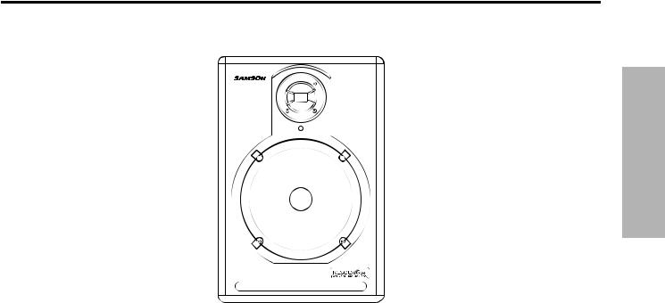
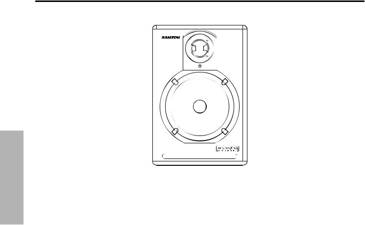
Thank you for purchasing the Samson RESOLV 65a Studio Reference Monitors. The Samson RESOLV 65a is a self powered 100 Watt monitor featuring an extended range 16.5 cm copolymer woofer and a 2.5 cm titanium dome tweeter. The RESOLV 65a is an ideal near field monitor system for studios, video post production suites, fixed installations or where great sound is desired.
In these pages, you’ll find a detailed description of the features of the RESOLV 65a subwoofer, as well as a guided tour through its control panel, step-by-step instructions for its setup and use, and full specifications.You’ll also find a warranty card enclosed—please don’t forget to fill it out and mail it in so that you can receive online technical support and so we can send you updated information about these and other Samson products in the future.
With proper care and adequate air circulation, your RESOLV 65a will operate trouble free for many years. We recommend you record your serial number in the space provided below for future refer-
ence
Serial number: ___________________
Date of purchase: _________________
Should your unit ever require servicing, a Return Authorization number (RA) must be obtained before shipping your unit to Samson. Without this number, the unit will not be accepted. Please call Samson at 1-800-3SAMSON (1-800-372-6766) for a Return Authorization number prior to shipping your unit. Please retain the original packing materials and if possible, return the unit in the original carton and packing materials.
2
RESOLV 65a Features
ENGLISH
The Samson RESOLV 65a reference monitors provide a smooth response that is accurate, and at the same time pleasant
to listen to. Here are some of its main features:
•Two-way, active studio reference monitor with ported tuned enclosure providing extremely accurate monitoring for recording studio, post-production and multi-media applications.
•16.5 cm Copolymer Butyl Surround woofer provides tight and controlled low frequency response.
•2.5 cm Titanium Dome tweeter with Neodymium magnet, plus Heat-sink and Ferro-Fluid
Cooling provides smooth and sweet high frequency response.
•Bi-Amp Power with 75 watts on the LF driver and 25 watts on the HF driver.
•Four-position midrange Presence control allows the user to contour the response curve to emulate monitors from hi-fi, through flat and all the way to aggressive midrange nearfield.
•Active crossover utilizing a multi-pole design for linear response from bottom to top.
•XLR and 1/4-inch balanced inputs, as well as unbalanced RCA inputs make connecting to most any -10
or + 4db signal source quick and easy.
•A/V shielded for multimedia applications providing clean operation near computer monitors.
•Solid MDF (Medium Density Fiberboard) construction, extremely rigid delivering maximum SPL.
•Black satin finish is attractive and durable thanks to the heavy textured epoxy paint.
•Three-year extended warranty.
3
RESOLV 65a Layout
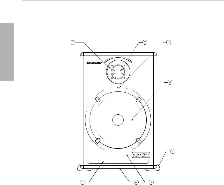
FrontView Layout
ENGLISH
1 |
2.5 CMTITANIUM DOMETWEETER - Smooth |
5 |
TUNED PORT - Quiet port design offering linear |
|
high frequency response produced from titani- |
|
extended low frequency response. |
|
um dome,Neodymium Magnet with Ferro-fluid |
|
|
|
plus Heat-sink cooling for high output. |
6 |
ENCLOSURE - Rigid MDF construction. |
2 |
PHASE PLUG - Insures even dispersion of the |
7 |
FINISH - Sleek black textured finish. |
|
high frequencies and improves off axis listening. |
|
|
|
|
8 |
NON-SKID FEET - Large rubber feet keep enclo- |
3 |
POWER LED - Blue LED illuminates indicating the |
|
sure in place even at high sound pressure levels. |
|
unit is powered on,ready for operation. |
|
|
416.5 CM LOW FREQUENCY DRIVER - Heavy duty
6.5,” extended range low frequency transducer
4
RESOLV 65a Layout
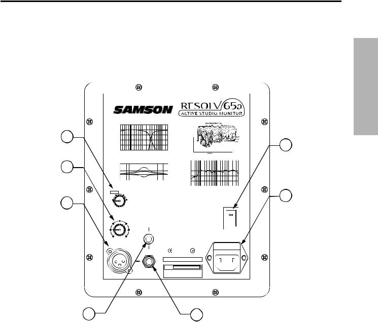
Rear Panel Layout
1MID RANGE CONTOUR CONTROL – Fourposition switch used to adjust the midrange response (in 3dB increments) providing customized voicing from hi-fi,to aggressive mid-range, near-field monitoring.
2VOLUME - Controls the amount of output level.
3XLR INPUT - Balanced,line level input is connected here via standard XLR (microphone) cable.
ENGLISH
4RCA – Used to connect signals from unbalanced,
–10dBV devices.
51/4-INCH PHONE – BalanceTRS (Tip,Ring, Sleeve) 1/4-inch phone plug used to connect balanced or unbalanced line level signals.
6POWER SWITCH – Main power switch.When set to the on position,illuminates green indicating the Resolv 65a is powered up and ready for operation.
7AC INLET - Connect the supplied IEC power cable here.
5
ENGLISH
Setting up the RESOLV 65a
Background on the Resolv 65a Studio Reference Monitor
The Resolv 65a is a near field reference monitor featuring a custom designed, 16.5 cm copolymer, low frequency driver and a 2.5 cm titanium tweeter, employing a Ferro fluid cooled voice coil and neodymium magnet. The monitor’s crossover has been carefully designed with high quality components insuring a linear frequency and phase response. The Resolv 65a enclosure is constructed from MDF (Medium Density Fiberboard) and is finished in scuff resistant, textured paint. The monitor’s enclosure also includes a tuned vent port that provides extended low-end response, and with a low turbulence design, the low frequency driver can move freely with minimal effect on the overall impedance. On the rear of the enclosure you’ll find Resolv 65a’s control panel, which features a variety of input connections including XLR balanced input, 1/4-inch TRS balance input and RCA unbalanced input. These inputs are connected to Resolv 65a’s internal bi-amp power module providing 75 watts of power for the low frequency woofer, an active crossover, and 25 watts of power for the high frequency tweeter.You will also find the pre-amp controls, including VOLUME knob, used to adjust the overall level of the internal power amplifier, as well as the innovative MID PRESENCE control. This four-posi- tion switch allows the mix engineer to contour the mid-range response of the monitor from a traditional hi-fi sound to flat and then through two levels of aggressive mid-range response. The Resolv 65a has been designed to provide flat, accurate monitoring, and at the same time, to provide an adjustable response curve so that the sound of other popular nearfield monitors can be easily emulated.
Positioning the Resolv 65a
Near field monitoring has become the choice of many engineers in large and small studios because it minimizes the effect of room acoustics. This is especially important in today’s project studios since the budget for room acoustics is often close to nothing. By positioning
the reference monitors in the near field
(close to the listeners), you can greatly reduce the effects of room acoustics. The most important considerations when evaluating the effects of room acoustics
are reflective surfaces that are around the monitoring area. These can include
flat tabletops, glass mirrors or framed pictures, large open walls and even the surface of your mixing console. Mostly all reflecting sound will eventually reach the listening position, but since it is slightly delayed from the direct source, the result is random cancellation of
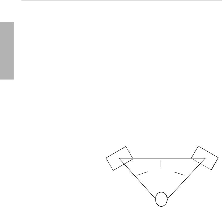
some frequencies, or comb filtering. If possible, remove any and all reflective surfaces.You may also want to hang some acoustic foam on walls that are close to the monitors. When positioning the monitors you’ll want to set up what is commonly referred to as the“mix triangle”. In this ideal configuration, the space between the left and right monitor is equal to the distance from the listener to each monitor, forming an equilateral triangle. (Figure 1.)
6
Setting up the RESOLV 65a
Positioning the Resolv 65 - continued
Speaker Orientation
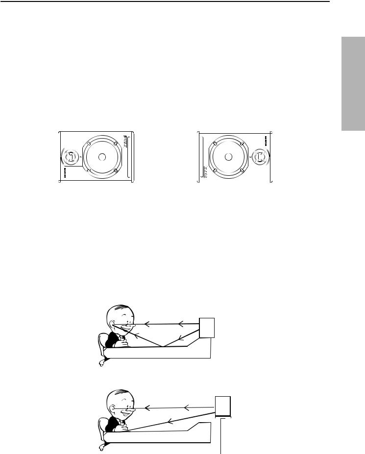
The Resolv 65a’s can be used in either the vertical or horizontal position. When using the monitors in the horizontal position, be certain to place the left and right side tweeters on the outer most sides. (Figure 2) This will improve the stereo imaging and bass response by increasing the coupling of the low-end drivers.
Figure 2.
A Moment of Reflection
When choosing the height of your monitor system, be careful to avoid reflections off the surface of the mixing console. (Figure 3.) These reflections arrive at the listening position slightly delayed from the original sound resulting in strange cancellations and overall unpredictable response. Visualize straight lines representing the beams of sound radiating from the monitors and choose a height that reduces the occurrence of reflections that will end up in the prime listening spot. (Figure 4.) In most cases, the ideal position is slightly behind and above the mixing console’s meter bridge.
Figure 3.
Figure 4.
ENGLISH
7
ENGLISH
Connecting the RESOLV 65a
Resolv 65a Quick Connections
Note: Before plugging in and turning on, remember the“last on first off”rule of power amplifiers (and powered monitors). When powering up your system, be sure that all the wires are connected, turn your mixer and any other outboard gear on, and then last turn your RESOLV 65a’s on. When powering down, turn your
RESOLV 65a’s off first and then your mixer and outboard gear.
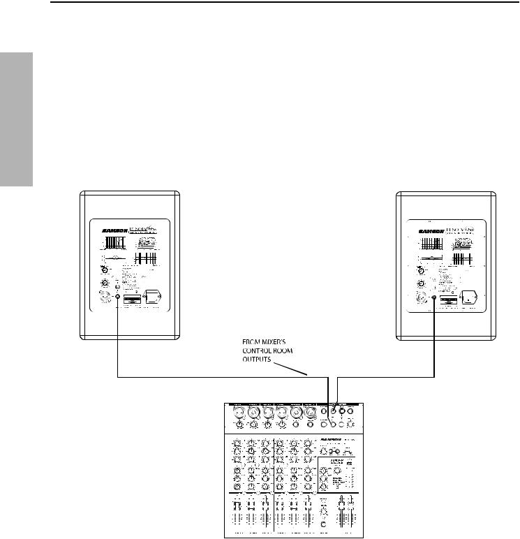
The Resolv 65a connections can be made via one of the three rear panel Audio Inputs. You can use RCA inputs for unbalanced -10dBV level signals, or either the 1/4-inch or XLR inputs for balanced +4dBu level signals. Follow the simple steps and diagram below for a quick connection using a standard recording console’s control room outputs.
•Lower your mixer’s master outputs to all the way off.
•Connect the mixer’s left Control Room output to the left-side RESOLV 65a LINE INPUT and the mixer’s right Control Room output to the right-side RESOLV 65a LINE INPUT.
•Set the Resolv 65a’s input Volume control to the 2 o’clock position.
Run an audio signal (like some music from a CD) through your mixer and raise the Control Room level to a comfortable listening level.
8
Operating the RESOLV 65a
RESOLV 65a Control Panel
The Resolv 65a’s rear control panel is where you will make your connections for both AC power and audio signals. The rear panel is also contains the controls to make adjustments to the overall volume and frequency response curve.The following section details the rear panel controls and connections.
Powering the Resolv 65a
Since the Resolv 65a is an active studio monitor with an on-board power amplifier and electronic crossover, it is necessary to connect the unit to an AC power supply. Make sure that the main Power switch is set to the off position and connect the supplied IEC power cable into the AC inlet.
Things that go Hum!
When running power cables, be careful not to run the AC power cords or AC extension cords in parallel to your input cables. This will help reduce any AC hum that can be picked up. If your have to cross an AC line with an audio line, try to cross them at a 90 degree angle for the least amount of induced hum. Using the
Resolv 65a’s balanced input connectors will greatly protect against the induced hum thanks to the common mode rejection (the induced hum is phase canceled) that its balanced input circuit provides.
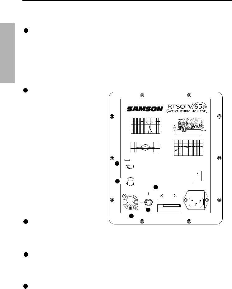
1POWER SWITCH – The POWER switch is used to turn on the Resolv 65a’s active electronics. When set to the on position, the internal LED will illuminate green, indicating the Resolv 65a is powered up and ready for operation. The Resolv 65a also has a blue LED which illuminates when the unit is powered up.
2AC INLET - Connect the supplied IEC power cable here.

 1
1


 2
2
The Resolv 65a’s rear panel provides two important controls for adjusting the overall sound of the monitor, Mid-Presence and Volume. Eventually, you will adjust these controls to your preferable position and “set it and forget it”. That’s assuming that the monitors remain in the same spot, in the same studio. If you take your monitors to other studios you may find the controls extremely useful in adjusting the sound for the new
oom
ENGLISH
9
Operating the RESOLV 65a
RESOLV 65a Control Panel - continued
|
3 MID PRESENCE CONTROL |
|
ENGLISH |
The four-position Mid Presence control switch is used to adjust the mid-range response (in 3dB incre- |
|
ments), providing customized voicing from hi-fi to aggressive mid-range, near-field monitoring. There |
||
are many mix engineers that prefer the sound of near field monitors that have an aggressive midrange |
||
|
||
|
response. In a typical recording, the mid range is often where many parts of the music compete for the |
|
|
same frequency range. Having a slight‘bump”is like having a microscope on the heavy traffic area. |
|
|
You’ll find that the change is very subtle. The best way to set the controls is what sounds good to you. |
|
|
Therefore, you should experiment with the various settings to find the combination of the Mid-Presence |
|
|
and Volume controls you like. To do this play several CD’s of music that you are familiar with. Remember, if |
|
|
you think you’re getting lost, the Resolv 65a is flat when the Presence control is set to the“0”position. |
4 VOLUME CONTROL
T h e v o l u m e c o n t r o l used to adjust the overall output level of the Resolv 65a. When operating the unit for the first time, start with the volume control set all the way off. Slowly raise the Volume control to reach a comfortable listening level.
The Ins andThe Outs
The RESOLV 65a features a full complement of input connectors providing easy installation with a variety of audio devices like recording consoles, hard disk recorders, CD players and computer sound cards, to name a few. The following section details the Resolv 65a’s input connectors. In addition, there is a detailed cable-wiring diagram on page
12.
5 BALANCED XLR AUDIO INPUT
is
3 


4 


 7
7
6
5
The Resolv 65a features a female
XLR connector that will accept bal-
anced or unbalanced +4dBm line level signal. If you are using a mixer that has balanced outputs on XLR connectors, you can make the connections via standard XLR (microphone) cable.
61/4-INCH PHONE AUDIO INPUT – A balanced TRS (Tip, Ring, Sleeve) 1/4-inch phone plug is used to connect balanced or unbalanced line level signals. The 1/4-inch input is a switching jack, so when a 1/4-inch connector is inserted into the jack, the RCA and/or XLR inputs are switched off and the 1/4-inch input is switched on. This provides a convenient patch point for quick insertion of a secondary signal source for testing or expanded operation.
 7 RCA AUDIO INPUT – The RCA input accepts unbalanced signals used to connect signals from unbalanced
–10dBV devices.
10
Connecting to the Resolv120a Subwoofer
Resolv 65a with Mono Sub
Adding a subwoofer and extended low frequency response to your Resolv 65a system is easy using the
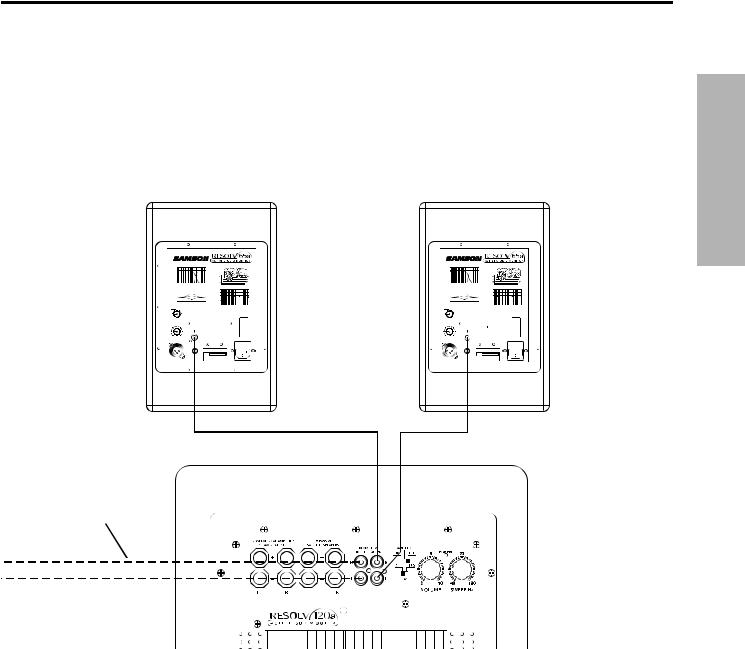
RESOLV 65a’s LINE LEVEL inputs. Below is a typical system set-up using the RESOLV 120a with a mixer and a pair of Resolv 65a’s satellite speakers. The RESOLV 65a’s inputs utilize industry standard RCA connectors. For a detailed wiring diagram, see the section“RESOLV 65a Connections”on page 12. Follow the steps in the diagram below to set up your system.
FROM MIXER
ENGLISH
•Lower your mixer’s master outputs to all the way off.
•Connect the mixer’s left output to the RESOLV 120’s LEFT LINE INPUT and the mixer’s right output to the RESOLV 120’s RIGHT LINE INPUT. Now connect the RESOLV 120’s LEFT LINE OUTPUT to the input of the left RESOLV 65a, and the RESOLV 120’s RIGHT LINE OUTPUT to the input of the right RESOLV 65a.
Run an audio signal (like some music from a CD) through your mixer and raise the level to a |
com- |
fortable listening level. |
|
•Now adjust the SWEEP control to the desired frequency. Consult your studio monitors owner’s manual for a recommended crossover point. You can also use your ears by adjusting the SWEEP control to the frequency that sounds good to you. A good place to start is about 70 Hz.
1

ENGLISH
RESOLV 65a Connections
RESOLV 65aWiring Guide
There are several ways to interface the RESOLV 65a, depending on your exact monitoring set-up. Follow the cable diagrams below for connecting your monitor system.
RCA to RCA Cable
Un-Balanced 1/4”to 1/4”Cable
Balanced 1/4”to 1/4”Cable
Balanced XLR to XLR Cable
Unbalanced 1/4”to RCA Cable
Un-Balanced XLR to RCA Cable
12

Introduction
Nous tenons à vous remercier d’avoir choisi les moniteurs de studio Samson RESOLV 65a. Les moniteurs Samson RESOLV 65a sont actifs, bi-amplifiés (75 + 25 Watts), d’un Woofer de 16,5 cm avec membrane en copolymère et d’un Tweeter à dôme au titane de 25 mm. Les RESOLV 65a sont d’excellents moniteurs de proximité pour les studios, la post-production vidéo, les installations fixes nécessitant des écoutes d’une qualité parfaite.
Dans ces pages, vous trouverez une description détaillée de toutes les fonctions des moniteurs
RESOLV 65a, ainsi qu’une description des réglages, des connexions, de son utilisation et de ses caractéristiques techniques. Vous trouverez également une carte d’enregistrement — n’oubliez pas de la remplir et de nous l’envoyer afin de recevoir notre lettre d’information et de pouvoir accéder à notre service technique.
Installez et utilisez votre RESOLV 65a avec soin et veillez à assurer une ventilation suffisante. Nous vous recommandons de noter le numéro de série du produit ci-dessous pour toute référence ultéri-
eure.
Numéro de série : _______________
Date d’achat : ___________________
Si vous devez faire réparer l’appareil, vous devez tout d’abord obtenir un numéro de retour auprès de Samson. Sans ce numéro, l’appareil sera refusé. Contactez Samson aux USA
au : 1-800-3SAMSON (1-800-372-6766) ou contactez votre revendeur. Les conditions de garantie et de retour varient selon le pays de distribution. Conservez l’emballage d’origine et utilisez-le pour tout retour en atelier.
FRANÇAIS
13
FRANÇAIS
Caractéristiques de moniteurs RESOLV 65a
®
Les moniteurs Samson RESOLV 65a offrent une réponse linéaire et précise tout en restant très agréables à l’écoute. Voici
les caractéristiques générales :
•Moniteur de studio actif deux voies avec baffle accordé offrant une écoute extrêmement fidèle pour les studios d’enregistrement, de post-production et les applications multi-media.
•Woofer de 16,5 cm avec suspension en Copolymère Butyle pour une réponse précise et étendue dans les basses fréquences.
•Tweeter à dôme au titane de 2,5 cm avec aimant au Néodymium. La structure de refroidissement et l’assemblage Ferro-Fluid offrent une réponse douce et fidèle dans les aigus.
•Bi-amplification : 75 Watts pour le Woofer et 25 Watts pour le Tweeter.
•Réglage de présence des médiums à quatre positions permettant d’émuler la réponse d’enceintes hifi, plates, ainsi qu’une accentuation sensible des médiums.
•Filtre actif multi-pôle pour une réponse linéaire sur toute l’étendue du spectre sonore.
•Entrées symétriques XLR et Jack 6,35 mm, et entrées asymétriques RCA permettant l’utilisation de signaux à -10 ou + 4 dB.
•Blindage magnétique pour les applications multimédia (utilisation près d’écrans vidéo).
•Baffle en panneaux de particules MDF, pour une puissance maximale exempte de vibrations.
•Finition noire satinée très robuste avec peinture ultra-résistante à base d’époxy.
•Garantie de 3 ans (variable selon le pays de distribution — consultez votre revendeur).
14
 Loading...