


Safety Instructions/Consignes de sécurité/Sicherheitsvorkehrungen
WARNING: To reduce the risk of fire or electric shock, do not expose this unit to rain or moisture. To reduce the hazard of electrical shock, do not remove cover or back. No user serviceable parts inside. Please refer all servicing to qualified personnel.The lightning flash with an arrowhead symbol within an equilateral triangle, is intended to alert the user to the presence of uninsulated "dangerous voltage" within the products enclosure that may be of sufficient magnitude to constitute a risk of electric shock to persons. The exclamation point within an equilateral triangle is intended to alert the user to the presence of important operating and maintenance (servicing) instructions in the literature accompanying the product.
Important Safety Instructions
1.Please read all instructions before operating the unit.
2.Keep these instructions for future reference.
3.Please heed all safety warnings.
4.Follow manufacturers instructions.
5.Do not use this unit near water or moisture.
6.Clean only with a damp cloth.
7.Do not block any of the ventilation openings. Install in accordance with the manufacturers instructions.
8.Do not install near any heat sources such as radiators, heat registers, stoves, or other apparatus (including amplifiers) that produce heat.
9.Do not defeat the safety purpose of the polarized or grounding-type plug. A polarized plug has two blades with one wider than the other. A grounding type plug has two blades and a third grounding prong. The wide blade or third prong is provided for your safety. When the provided plug does not fit your outlet, consult an electrician for replacement of the obsolete outlet.
10.Protect the power cord from being walked on and pinched particularly at plugs, convenience receptacles and at the point at which they exit from the unit.
11.Unplug this unit during lightning storms or when unused for long periods of time.
12.Refer all servicing to qualified personnel. Servicing is required when the unit has been damaged in any way, such as power supply cord or plug damage, or if liquid has been spilled or objects have fallen into the unit, the unit has been exposed to rain or moisture, does not operate normally, or has been dropped.
ATTENTION: Pour éviter tout risque d’électrocution ou d’incendie, ne pas exposer cet appareil à la pluie ou à l’humidité. Pour éviter tout risque d’électrocution, ne pas ôter le couvercle ou le dos du boîtier. Cet appareil ne contient aucune pièce remplaçable par l'utilisateur. Confiez toutes les réparations à un personnel qualifié. Le signe avec un éclair dans un triangle prévient l’utilisateur de la présence d’une tension dangereuse et non isolée dans l’appareil. Cette tension constitue un risque d’électrocution. Le signe avec un point d’exclamation dans un triangle prévient l’utilisateur d’instructions importantes relatives à l’utilisation et à la maintenance du produit.
Consignes de sécurité importantes
1.Veuillez lire toutes les instructions avant d’utiliser l’appareil.
2.Conserver ces instructions pour toute lecture ultérieure.
3.Lisez avec attention toutes les consignes de sécurité.
4.Suivez les instructions du fabricant.
5.Ne pas utiliser cet appareil près d’une source liquide ou dans un lieu humide.
6.Nettoyez l’appareil uniquement avec un tissu humide.
7.Veillez à ne pas obstruer les fentes prévues pour la ventilation de l’appareil. Installez l’appareil selon les instructions du fabricant.
8.Ne pas installer près d’une source de chaleur (radiateurs, etc.) ou de tout équipement susceptible de générer de la chaleur (amplificateurs de puissance par exemple).
9.Ne pas retirer la terre du cordon secteur ou de la prise murale. Les fiches canadiennes avec polarisation (avec une lame plus large) ne doivent pas être modifiées. Si votre prise murale ne correspond pas au modèle fourni, consultez votre électricien.
10.Protégez le cordon secteur contre tous les dommages possibles (pincement, tension, torsion,, etc.). Veillez à ce que le cordon secteur soit libre, en particulier à sa sortie du boîtier.
11.Déconnectez l’appareil du secteur en présence d’orage ou lors de périodes d’inutilisation prolongées.
12.Consultez un service de réparation qualifié pour tout dysfonctionnement (dommage sur le cordon secteur, baisse de performances, exposition à la pluie, projection liquide dans l’appareil, introduction d’un objet dans le boîtier, etc.).
ACHTUNG: Um die Gefahr eines Brandes oder Stromschlags zu verringern, sollten Sie dieses Gerät weder Regen noch Feuchtigkeit aussetzen.Um die Gefahr eines Stromschlags zu verringern, sollten Sie weder Deckel noch Rückwand des Geräts entfernen. Im Innern befinden sich keine Teile, die vom Anwender gewartet werden können. Überlassen Sie die Wartung qualifiziertem Fachpersonal.Der Blitz mit Pfeilspitze im gleichseitigen Dreieck soll den Anwender vor nichtisolierter “gefährlicher Spannung” im Geräteinnern warnen. Diese Spannung kann so hoch sein, dass die Gefahr eines Stromschlags besteht. Das Ausrufezeichen im gleichseitigen Dreieck soll den Anwender auf wichtige Bedienungsund Wartungsanleitungen aufmerksam machen, die im mitgelieferten Informationsmaterial näher beschrieben werden.
Wichtige Sicherheitsvorkehrungen
1.Lesen Sie alle Anleitungen, bevor Sie das Gerät in Betrieb nehmen.
2.Bewahren Sie diese Anleitungen für den späteren Gebrauch gut auf.
3.Bitte treffen Sie alle beschriebenen Sicherheitsvorkehrungen.
4.Befolgen Sie die Anleitungen des Herstellers.
5.Benutzen Sie das Gerät nicht in der Nähe von Wasser oder Feuchtigkeit.
6.Verwenden Sie zur Reinigung des Geräts nur ein feuchtes Tuch.
7.Blockieren Sie keine Belüftungsöffnungen. Nehmen Sie den Einbau des Geräts nur entsprechend den Anweisungen des Herstellers vor.
8.Bauen Sie das Gerät nicht in der Nähe von Wärmequellen wie Heizkörpern, Wärmeklappen, Öfen oder anderen Geräten (inklusive Verstärkern) ein, die Hitze erzeugen.
9.Setzen Sie die Sicherheitsfunktion des polarisierten oder geerdeten Steckers nicht außer Kraft. Ein polarisierter Stecker hat zwei flache, unterschiedlich breite Pole. Ein geerdeter Stecker hat zwei flache Pole und einen dritten Erdungsstift. Der breitere Pol oder der dritte Stift dient Ihrer Sicherheit. Wenn der vorhandene Stecker nicht in Ihre Steckdose passt, lassen Sie die veraltete Steckdose von einem Elektriker ersetzen.
10.Schützen Sie das Netzkabel dahingehend, dass niemand darüber laufen und es nicht geknickt werden kann. Achten Sie hierbei besonders auf Netzstecker, Mehrfachsteckdosen und den Kabelanschluss am Gerät.
11.Ziehen Sie den Netzstecker des Geräts bei Gewittern oder längeren Betriebspausen aus der Steckdose.
12.Überlassen Sie die Wartung qualifiziertem Fachpersonal. Eine Wartung ist notwendig, wenn das Gerät auf irgendeine Weise, beispielsweise am Kabel oder Netzstecker beschädigt wurde, oder wenn Flüssigkeiten oder Objekte in das Gerät gelangt sind, es Regen oder Feuchtigkeit ausgesetzt war, nicht mehr wie gewohnt betrieben werden kann oder fallen gelassen wurde.

Instrucciones de seguridad / Istruzioni di Sicurezza
PRECAUCION: Para reducir el riesgo de incendios o descargas, no permita que este aparato quede expuesto a la lluvia o la humedad. Para reducir el riesgo de descarga eléctrica, nunca quite la tapa ni el chasis. Dentro del aparato no hay piezas susceptibles de ser reparadas por el usuario. Dirija cualquier reparación al servicio técnico oficial. El símbolo del relámpago dentro del triángulo equilátero pretende advertir al usuario de la presencia de “voltajes peligrosos” no aislados dentro de la carcasa del producto, que pueden ser de la magnitud suficiente como para constituir un riesgo de descarga eléctrica a las personas. El símbolo de exclamación dentro del triángulo equilátero quiere advertirle de la existencia de importantes instrucciones de manejo y mantenimiento (reparaciones) en los documentos que se adjuntan con este aparato.
Instrucciones importantes de seguridad
1.Lea todo este manual de instrucciones antes de comenzar a usar la unidad.
2.Conserve estas instrucciones para cualquier consulta en el futuro.
3.Cumpla con todo lo indicado en las precauciones de seguridad.
4.Observe y siga todas las instrucciones del fabricante.
5.Nunca utilice este aparato cerca del agua o en lugares húmedos.
6.Limpie este aparato solo con un trapo suave y ligeramente humedecido.
7.No bloquee ninguna de las aberturas de ventilación. Instale este aparato de acuerdo a las instrucciones del fabricante.
8.No instale este aparato cerca de fuentes de calor como radiadores, calentadores, hornos u otros aparatos (incluyendo amplificadores) que produzcan calor.
9.No anule el sistema de seguridad del enchufe de tipo polarizado o con toma de tierra. Un enchufe polarizado tiene dos bornes, uno más ancho que el otro. Uno con toma de tierra tiene dos bornes normales y un tercero para la conexión a tierra. El borne ancho o el tercero se incluyen como medida de seguridad. Cuando el enchufe no encaje en su salida de corriente, llame a un electricista para que le cambie su salida anticuada.
10.Evite que el cable de corriente quede en una posición en la que pueda ser pisado o aplastado, especialmente en los enchufes, receptáculos y en el punto en el que salen de la unidad.
11.Desconecte de la corriente este aparato durante las tormentas eléctricas o cuando no lo vaya a usar durante un periodo de tiempo largo.
12.Dirija cualquier posible reparación solo al servicio técnico oficial. Deberá hacer que su aparato sea reparado cuando esté dañado de alguna forma, como si el cable de corriente o el enchufe están dañados, o si se han derramado líquidos o se ha introducido algún objeto dentro de la unidad, si esta ha quedado expuesta a la lluvia o la humedad, si no funciona normalmente o si ha caído al suelo.
ATTENZIONE: per ridurre il rischio di incendio o di scariche elettriche, non esponete questo apparecchio a pioggia o umidità. Per ridurre il pericolo di scariche elettriche evitate di rimuoverne il coperchio o il pannello posteriore. Non esistono all'interno dell'apparecchio parti la cui regolazione è a cura dell'utente. Per eventuale assistenza, fate riferimento esclusivamente a personale qualificato. Il fulmine con la punta a freccia all'interno di un triangolo equilatero avvisa l'utente della presenza di "tensioni pericolose" non isolate all'interno dell'apparecchio, tali da costituire un possibile rischio di scariche elettriche dannose per le persone. Il punto esclamativo all'interno di un triangolo equilatero avvisa l'utente della presenza di importanti istruzioni di manutenzione (assistenza) nella documentazione che accompagna il prodotto.
Importanti Istruzioni di Sicurezza
1.Prima di usare l'apparecchio, vi preghiamo di leggerne per intero le istruzioni.
2.Conservate tali istruzioni per una eventuale consultazione futura.
3.Vi preghiamo di rispettare tutte le istruzioni di sicurezza.
4.Seguite tutte le istruzioni del costruttore.
5.Non usate questo apparecchio vicino ad acqua o umidità.
6.Pulite l'apparecchio esclusivamente con un panno asciutto.
7.Evitate di ostruire una qualsiasi delle aperture di ventilazione. Posizionatelo seguendo le istruzioni del costruttore.
8.Non posizionatelo vicino a sorgenti di calore come radiatori, scambiatori di calore, forni o altri apparecchi (amplificatori compresi) in grado di generare calore.
9.Non disattivate la protezione di sicurezza costituita dalla spina polarizzata o dotata di collegamento a terra. Una spina polarizzata è dotata di due spinotti, uno più piccolo ed uno più grande. Una spina dotata di collegamento a terra è dotata di due spinotti più un terzo spinotto di collegamento a terra. Questo terzo spinotto, eventualmente anche più grande, viene fornito per la vostra sicurezza. Se la spina fornita in dotazione non si adatta alla vostra presa, consultate un elettricista per la sostituzione della presa obsoleta.
10.Proteggete il cavo di alimentazione in modo che non sia possibile camminarci sopra né piegarlo, con particolare attenzione alle prese, ai punti di collegamento e al punto in cui esce dall'apparecchio.
11.Staccate l'apparecchio dalla alimentazione in caso di temporali o tempeste o se non lo usate per un lungo periodo.
12.Per l'assistenza, fate riferimento esclusivamente a personale qualificato. È necessaria l'assistenza se l'apparecchio ha subito un qualsiasi tipo di danno, come danni al cavo o alla spina di alimentazione, nel caso in cui sia stato versato del liquido o siano caduti oggetti al suo interno, sia stato esposto a pioggia o umidità, non funzioni corret-
tamente o sia stato fatto cadere.
Table of Contents
ENGLISH
Introduction. . . . . . . . . . . . . . . . . . . . . 1 Live Series Features. . . . . . . . . . . . . . . . . . 2 L612 and L615 Layout. . . . . . . . . . . . . . . . . 3 L1212 and L1215 Layout . . . . . . . . . . . . . . . 4 L612M Layout. . . . . . . . . . . . . . . . . . . . . 5 L612 and L615 Quick Set-Up. . . . . . . . . . . . . . 6 L1212 and L1215 Quick Set-Up. . . . . . . . . . . . 7 Positioning the Live Series . . . . . . . . . . . . . . 8 Operating the Live Series . . . . . . . . . . . . . . . 9 Operating the Live Series . . . . . . . . . . . . . . 10 Live Series System Set-ups . . . . . . . . . . . . . . 11 Live Band PA System With Monitors. . . . . . . . . . 12 LIVE! Series Wiring Guide. . . . . . . . . . . . . . . 13 Specifications. . . . . . . . . . . . . . . . . . . . 66
FRANÇAIS
Introduction. . . . . . . . . . . . . . . . . . . . . 14 Série Live - Caractéristiques . . . . . . . . . . . . . 15 Composants des L612 et L615. . . . . . . . . . . . 16 Composants des L1212 et L1215. . . . . . . . . . . . . . . . . . . . . 17 Composants des L612M . . . . . . . . . . . . . . . 18 Configuration rapide des L612 et L615. . . . . . . . 19 Configuration rapide des L1212 et L1215 . . . . . . . 20 Positionnement des enceintes Live. . . . . . . . . . 21 Utilisation des enceintes de la série Live . . . . . . . 22 Utilisation des enceintes de la série Live . . . . . . . 23 Schémas d’installation . . . . . . . . . . . . . . . . 24 Schémas d’installation . . . . . . . . . . . . . . . . 25 Système de sonorisation avec retours de scène . . . . 25 Connexions des enceintes de la série LIVE. . . . . . . 26 Caractéristiques techniques. . . . . . . . . . . . . . 6
DEUTSCHE
Einleitung . . . . . . . . . . . . . . . . . . . . . . 27 Features der Live-Serie. . . . . . . . . . . . . . . . 28 L612 und L615 Layout. . . . . . . . . . . . . . . . 29 L1212 und L1215 Layout. . . . . . . . . . . . . . . 30 L612M Layout. . . . . . . . . . . . . . . . . . . . 31 Schnelleinrichtung des L612 und L615. . . . . . . . 32
Copyright 2007, Samson Technologies Corp.
Printed June, 2008 - v1.1
Samson Technologies Corp. 45 Gilpin Avenue
Hauppauge, New York 11788-8816 Phone: 1-800-3-SAMSON (1-800-372-6766) Fax: 631-784-2201
www.samsontech.com
Schnelleinrichtung des L1212 und L1215. . . . . . . 33 Live-Serie positionieren . . . . . . . . . . . . . . . 34 Live-Serie bedienen . . . . . . . . . . . . . . . . . 35 Live-Serie bedienen . . . . . . . . . . . . . . . . . 36 Systemeinrichtungen der Live-Serie. . . . . . . . . 37 PA-System mit Monitoren für eine Live-Band. . . . . 38 Verdrahtung der LIVE! Serie . . . . . . . . . . . . . 39 Technische Daten. . . . . . . . . . . . . . . . . . 68
ESPAÑOL
Introducción. . . . . . . . . . . . . . . . . . . . . 40 Características de los Live Series. . . . . . . . . . . 41 Distribución del L612 y L615. . . . . . . . . . . . . . . . . . . . . . . . . 42 Distribución del L1212 y L1215. . . . . . . . . . . . 43 Distribución del L612M. . . . . . . . . . . . . . . . . . . . . . . . . . . . . . 44 Puesta en marcha del L612 y L615. . . . . . . . . . 45 Puesta en marcha del L1212 y L1215. . . . . . . . . 46 Colocación de los Live Series . . . . . . . . . . . . . 47 Manejo de los Live Series . . . . . . . . . . . . . . 48 Manejo de los Live Series . . . . . . . . . . . . . . 49 Configuración de sistemas Live Series . . . . . . . . 50 Sistema PA con monitores para directo . . . . . . . . 51 Guía de cableado de los LIVE! Series. . . . . . . . . 52 Especificaciones técnicas. . . . . . . . . . . . . . . 69
ITALIANO
Introduzione. . . . . . . . . . . . . . . . . . . . . 53 Le Caratteristiche della Serie Live. . . . . . . . . . . 54 L612 ed L615 in Dettaglio. . . . . . . . . . . . . . 55 L1212 ed L1215 in Dettaglio. . . . . . . . . . . . . 56 L612M in Dettaglio. . . . . . . . . . . . . . . . . 57 L612 ed L615 - Configurazione . . . . . . . . . . . . 58 L1212 ed L1215 - Configurazione. . . . . . . . . . . 59 Il Posizionamento della Serie Live . . . . . . . . . . 60 L’Uso della Serie Live . . . . . . . . . . . . . . . . . 61 L’Uso della Serie Live . . . . . . . . . . . . . . . . . 62 Configurazioni d’Uso della Serie Live Live. . . . . . . 63 Configurazioni d’Uso della Serie Live Live. . . . . . . 64 Sistema di PA con Monitor per un Gruppo dal Vivo. . 64 Serie LIVE! - Guida al Cablaggio. . . . . . . . . . . . 65 Specifiche . . . . . . . . . . . . . . . . . . . . . . 70

Introduction
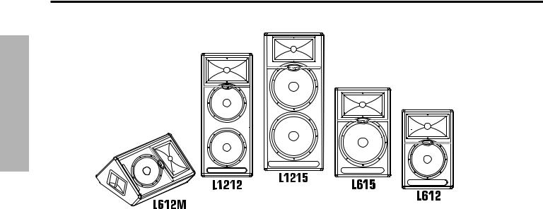
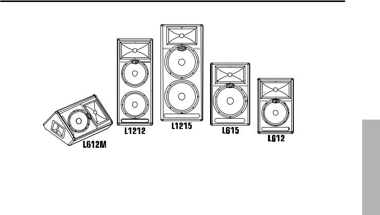
Congratulations on purchasing the Samson Live Series active loudspeaker! By combining super clean power, advanced active processing and the highest quality speaker and cabinet components, the Live Series provides studio quality sound for any kind of live sound reinforcement application. The Live Series product range includes five enclosures, the L612, L612M, L615, L1212 and L1215, and this manual covers the operation and specifications of each model. The L612, L615, L1212 and L1215 trapezoidal enclosures are configured as “front of house” loudspeakers while the L612M is configured as a dedicated low profile floor monitor. The L612 , L612M and L1212 are 2-way, active speaker systems utilizing super heavy-duty, custom designed, 12-inch low frequency drivers and a 1.75-inch titanium diaphragm high frequency driver on a 1” throat, wide dispersion horn. The L615 and L1215 are 2-way, active, speaker systems that employ super heavy-duty, custom designed, 15-inch low frequency drivers and a 1.75-inch titanium diaphragm high frequency driver on a 1” throat,
wide dispersion horn. The L612, L612M and L615 drive units are powered by their internal 300-watt bi-amp amplifier module with 250 watts for the Low Frequency driver and 50 watts for the High Frequency driver. The L1212 and L1215 feature a massive 400 watts of power for the dual Low Frequency drivers, plus 100 watts for the High Frequency compression driver. All of the LIVE series amplifiers feature a built-in active crossover and multi-band dynamics processing. The L612 and L615 models offer a practical back-panel, mixer-like preamp section that provides mic and line inputs with individual input level controls. In addition, the models have a two band EQ and controls for the extension output selection. The Live Series goes beyond concert-quality
to studio-quality thanks to Samson’s exclusive Optimax processing. Optimax processing uses sophisticated circuitry to compress and limit output at ideal levels. This allows the Live Series to provide huge volume levels without sacrificing low end. The trapezoidal shape of the speaker cabinet offers more than just superior acoustics, not only is it a front-firing PA speaker, the Live Series are also designed to operate as wedge-style monitors. With the Live Series, setup and break down is quick and easy thanks to the internal amplification. The L612 and L615’s can be easily stand mounted using the integral 1 3/8” pole mount receptacle. If you
are traveling to different venues with your loudspeaker system, the heavy-grade steel grill and durable carpet covering offer excellent protection against wear and tear on the road. By using clean power and over designed components, the Live Series offers crystal-clear audio and an ultra-wide sound field. The top end is clear, sweet and articulate. The low-end is enormous, and at the same time, it’s tight and controlled. As fixed sound reinforcement or as a durable, great-sounding road PA, the Live Series active monitor is ideal for sound professionals and performers looking for serious power and studio monitor sound quality from a PA speaker system.
In these pages, you’ll find a detailed description of the features of the Live Series PA system, as well as a description of its front and rear panels, step-by-step instructions for its setup and use, and full specifications. You’ll also find a warranty card enclosed—please don’t forget to fill it out and mail it in so that you can receive online technical support and so we can send you updated information about these and other Samson products in the future. Also, be sure to check out our website (www.samsontech.com) for complete information about our full product line.
With proper care and adequate air circulation, your Live Series will operate trouble free for many years. We recommend you record your serial number in the space provided below for future reference.
Serial number:_______________________________
Date of purchase:____________________________
Should your unit ever require servicing, a Return Authorization number (RA) must be obtained before shipping your unit to Samson. Without this number, the unit will not be accepted. Please call Samson at 1-800- 3SAMSON (1-800-372-6766) for a Return Authorization number prior to shipping your unit. Please retain the original packing materials and if possible, return the unit in the original carton and packing materials. If you purchased your Samson product outside the United States, please contact your local distributor for warranty information and service.
ENGLISH
Live Series Features
ENGLISH
The Samson Live Series active two-way loudspeakers are an all-in-one solution, ideal for most any live sound applications. Here are some of their main features:
•Two-way active, Bi-amped professional loudspeaker enclosures.
•The LIVE series enclosures feature custom designed, heavy-duty, low frequency drivers with a single 12inch in the L612 and L612M, dual 12-inch in the L1212, single 15-inch in the L615 and dual 15-inch in the L1215. All the drivers feature oversize motors and large voice coils.
•The articulate high frequency response is achieved by the 1" throat, high-frequency compression driver with 1.75-inch titanium diaphragm.
•The L612, L612M, and L615 feature 300 watts of power with an efficient 250 watt, class AB amplifier for low frequency transducer, with 50 watt class AB amplifier for high frequency compression driver. The L1212 and L1215 amplifiers deliver 400 watts to the dual low frequency drivers, plus 100 watts to the high frequency compression driver.
•All models feature a balanced line level input with LEVEL control and PEAK indicator.
•The L612 and L615 have a balanced microphone input with level control and Phantom Power for powering condenser microphones plus separate bass and treble controls and a selectable low cut filter.
•For increased reliability, the LIVE series power amplifiers all feature large heatsinks and massive power transformers.
•Sophisticated, multi-band dynamics processor with audibly transparent limiting.
•Internal 24 dB/octave time aligned electronic crossover.
•Multi-point amplifier protection with LED indicator for all fault conditions.
•The L612 and L615 can be stand mounted using the standard 1 3/8-inch (35mm) speaker stand receptacle.
•Rigid all-plywood enclosures forces the maximum energy to the sound field while the rugged, roadworthy construction provides enhanced high reliability.
•Three-year extended warranty.
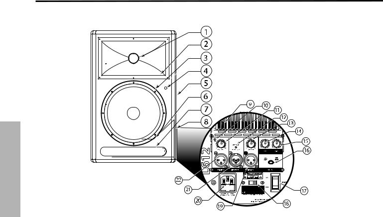
L612 and L615 Layout
ENGLISH
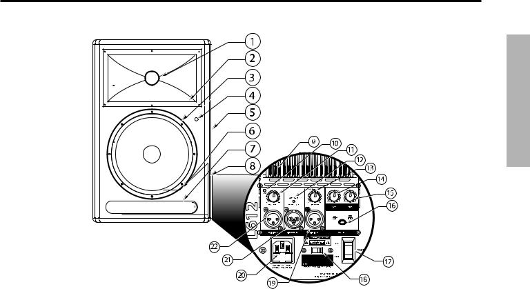
1.Titanium Compression Driver – 1.75 inch (44mm), titanium diaphragm with 1 inch opening.
2.Wide Dispersion Horn – 1 inch throat, 60 x 90 degree wide dispersion horn provides extensive coverage and linear off-axis response.
3.Low Frequency Driver - 12-inch and 15-inch woofers with oversize motors and 3-inch voice coils deliver deep, controlled bass response.
4.Power LED – Blue Light Emitting Diode illuminates indicating the unit is powered on and ready for operation.
5.Handle – One of two over sized carry handles.
6.Steel Grill – Durable steel grill provides protection for, and easy access to LF driver.
7.Bass Port– A precision tuned, low frequency port, extends the bass response.
8.Enclosure – Rigid, all-plywood enclosure for maxmum output and durability.
Amplifier Panel Rear View
9.Heat sink - Convection cooling of the internal power amplifier via massive aluminum extrusion.
10.PEAK LED - LED light to indicate mic input peak.
11.MIC LEVEL – Used to adjust the volume of the microphone input.
12.AMP / CLIP LED - Dual color LED lights Green when amp is active, flashes Red when the amp is clipped or stays Red indicating the amplifier is in protect mode.
13.LINE LEVEL – Used to control the level of the line input.
14.LOW FREQUENCY - Controls the low band of the Channel Equalizer, +/- 12 dB at 100Hz.
15.HIGH FREQUENCY - Controls the high band of the Channel Equalizer, +/- 12 dB at 10kHz.
16.OUTPUT switch - This switch is used to select the signal that is sent to the Line Output. When the switch is in the up position, the signal on the Line Output is exactly the same as the signal on the Input. When the switch is in the down position, the Line Output carries the MIX of the Mic and Line Inputs, as well as the High and Low Equalizer.
17.POWER – Switches on the LIVE series’ main power.
18.VOLTAGE switch - Used to change the operating voltage from 115 to 230 volts.
IMPORTANT NOTE! Bure sure to confirm and install the properly rated fuse when changing the operating voltage. (See below AC Power Inlet).
19.LINE INPUT connector - XLR Input for connecting balanced line level signals.
20.AC Power inlet / Fuse Sled– Connect the supplied standard IEC AC power cable here.
21.LINE OUTPUT connector- Male XLR connector used to link multiple LIVE series.
22.MIC INPUT connector - XLR Input for connecting low impedance microphones to the Low-Noise pre-amp and Phantom Power.
L1212 and L1215 Layout
ENGLISH
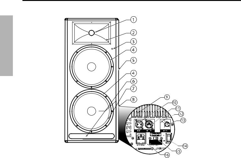
1.Titanium Compression Driver – 1.75 inch (44mm), titanium diaphragm with 1 inch opening.
2.Wide Dispersion Horn – 1 inch throat, 60 x 90 degree wide dispersion horn provides extensive coverage and linear offaxis response.
3.Power LED – Blue Light Emitting Diode illuminates indicating the unit is powered on and ready for operation.
4.Low Frequency Driver - 12-inch and 15-inch woofers with oversize motors and large voice coils deliver deep, controlled bass response.
5.Handle – One of two over sized carry handles.
6.Bass Port– Precision tuned, low frequency port extends the bass response.
7.Steel Grill – Durable steel grill provides protection for, and easy access to LF driver.
8.Enclosure – Rigid, all-plywood enclosure for maxmum output and durability.
Amplifier Panel Rear View
9.Heat sink - Convection cooling of the internal power amplifier via massive aluminum extrusion.
10.LINE INPUT connector - XLR Input for connecting balanced line level signals.
11.LINE OUTPUT connector- Male XLR connector used to link multiple LIVE series.
12.AMP / CLIP LED - Dual color LED lights Green when amp is active, flashes Red when the amp is clipped or stays Red indicating the amplifier is in protect mode.
13.LINE LEVEL – Used to control the level of the line input.
14.POWER – Switches on the LIVE series’ main power.
15.VOLTAGE switch - Used to change the operating voltage from 115 to 230 volts.
IMPORTANT NOTE! Bure sure to confirm and install the properly rated fuse when changing the operating voltage. (See below AC Power Inlet).
16.AC Power inlet / Fuse Sled– Connect the supplied standard IEC AC power cable here.
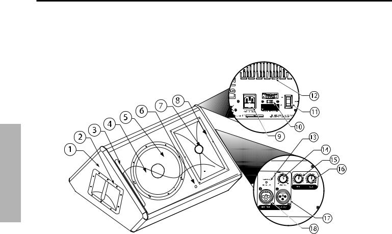
L612M Layout
ENGLISH
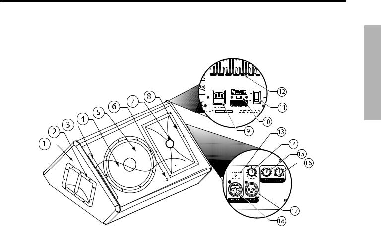
1.Enclosure – Rigid, all-plywood enclosure for maxmum output and durability.
2.Handle – Oversize carry handle.
3.Bass Port– Precision tuned, low frequency port extends the bass response.
4.Steel Grill – Durable steel grill provides protection
5.Low Frequency Driver - 12-inch woofer with oversize motor and 3-inch voice coil deliver deep, controlled bass response.
6.Power LED – Blue Light Emitting Diode illuminates indicating the unit is powered on and ready for operation.
7Titanium Compression Driver – 1.75 inch (44mm), titanium diaphragm with 1 inch opening.
8.Wide Dispersion Horn – 1 inch throat, 60 x 90 degree wide dispersion horn provides extensive coverage and linear offaxis response.
Amplifier Panel Rear View
9.AC Power inlet / Fuse Sled – Connect the supplied standard IEC AC power cable here.
10.VOLTAGE switch - Used to change the operating voltage from 115 to 230 volts.
IMPORTANT NOTE! Bure sure to confirm and install the properly rated fuse when changing the operating voltage. (See above AC Power Inlet).
11.POWER – Switches on the L612Ms main power.
12.Heat sink - Convection cooling of the internal power amplifier via massive aluminum extrusion.
Amplifier Panel Side Viewv
13.AMP / CLIP LED - Dual color LED lights Green when amp is active, flashes Red when the amp is clipped or stays Red indicating the amplifier is in protect mode.
14.LINE LEVEL – Used to control the level of the line input.
15.LOW FREQUENCY - Controls the low band of the Channel Equalizer, +/- 12 dB at 100Hz.
16.HIGH FREQUENCY - Controls the high band of the Channel Equalizer, +/- 12 dB at 10kHz.
17.LINE INPUT connector - XLR Input for connecting balanced line level signals.
18.LINE OUTPUT connector- Male XLR connector used to link multiple L612M’s.
ENGLISH
L612 and L615 Quick Set-Up
In the following pages of this manual, you will find a detailed explanation of all the Live Series functions and controls, but if you just want to get started quickly with the L612 and L615 you can follow the steps below.
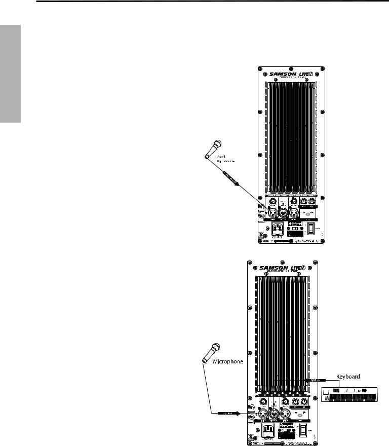
Using a Microphone
• Be sure that the Live Series Power switch is set to the off position.
• Turn the LINE and MIC LEVEL controls fully counterclockwise to the off position.
• Connect the power cable to an AC socket.
• Using a standard XLR cable, plug a microphone into the Live Series MIC INPUT.
• Switch the Live Series Power switch to the ON position.
• While speaking into the microphone, slowly raise the MIC LEVEL control until you have reached the desired level.
Using a Line Level Signal
• Be sure that the Live Series Power switch is set to the off position.
•Turn the LINE and MIC LEVEL controls fully counterclockwise to the off position.
• Connect the power cable to an AC socket.
• Using a standard XLR cable, connect a line level signal from a mixer or keyboard into the Live Series LINE INPUT.
• Switch the Live Series Power switch to the ON position.
• Now, run an audio signal from your mixer (like some music from a CD) while slowly raising the Live Series LINE LEVEL control until you have reached the desired level.
IMPORTANT NOTE!!: Be sure to keep the MIC LEVEL control all the way off if there is no microphone connected.
IMPORTANT NOTE!!: Be sure to watch the PEAK LED, as it should only light RED occasionally. Operating the speaker while the PEAK LED stays on RED could cause catastrophic damage to your speaker. So be sure to lower the mixers output or the LINE LEVEL input control until the PEAK LED lights RED only occasionally.
L1212 and L1215 Quick Set-Up
In the following pages of this manual, you will find a detailed explanation of all the Live Series functions and controls, but if you just want to get started quickly with the L1212 and L1215 you can follow the steps below.
Using a Line Level Signal
•Be sure that the Live Series
speakers’ Power switch is set 


 to the off position.


•Turn the LINE controls fully 
 counterclockwise to the off


 position.


•Connect the power cables 


 to an AC socket.


•Connect your turntables or 


 CD players to your DJ mixer


following the manufacturers 


 instructions.


•Using a standard XLR cable,
connect the mixer’s left 


 output to the left side Live


Series’ LINE INPUT and then 

 connect the mixer’s right


 output to the right side LIVE
series’ LINE INPUT. 


•Switch the Live Series Power switch to the ON position.
•Now, run an audio signal (like some music from a CD) from your mixer and check that you are getting a good level using the mixers output meter.
•Next, slowly raise the Live Series LINE LEVEL control until you have reached the desired level.
IMPORTANT NOTE!!: Be sure to watch the PEAK LED, as it should only light RED occasionally. Operating the speaker while the PEAK LED stays on RED could cause catastrophic damage to your speaker. So be sure to lower the mixers output or the LINE LEVEL input control until the PEAK LED lights RED only occasionally.
ENGLISH
ENGLISH
Positioning the Live Series
Microphone Positioning - How to Reduce Feedback
Feedback is the annoying howling and squealing that is heard when the microphone gets too close to the speaker and the volume is high. You get feedback when the microphone picks up the amplified signal from the speaker, and then amplifies through the speaker again, and then picks it up again, and so on and so on. In general, it is always recommended that any live mic (a mic that’s on) is positioned behind the speaker enclosures. This will give you the best level from your system before feedback. One possible exception is when you are adjusting the sounds of the microphones, since you want to listen in front of the speaker to hear properly. To do this, lower your mixers MAIN VOLUME while setting the EQ and effect from in front of the speakers. Once you have the sound you like, move the microphones to behind the speakers and raise the Main volume.
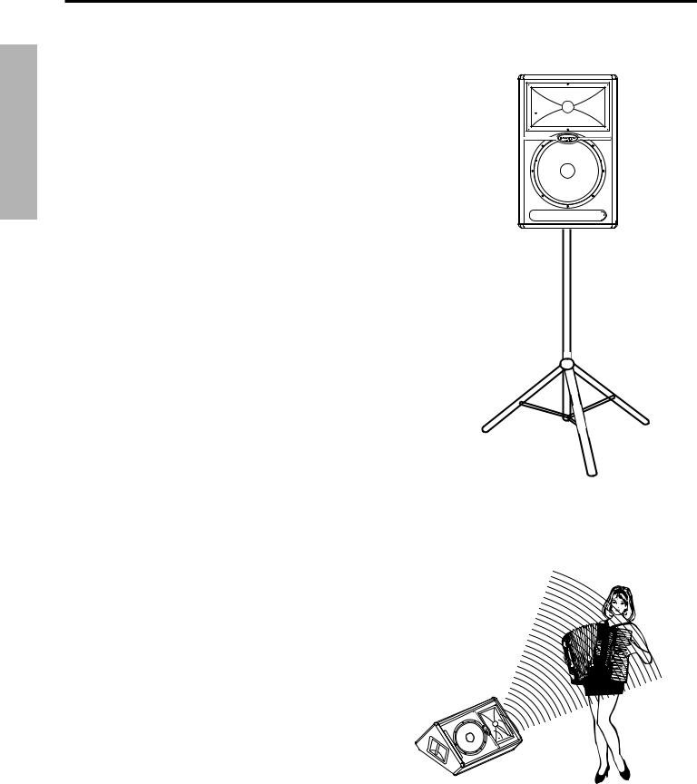
Speaker Placement
Whenever possible, it is a good idea to raise the speakers above the heads of the listening audience. The L612, and L615 enclosures’ feature standard 1 3/8” pole mount receptacles, which are compatible with speaker stands from a variety of manufacturers. In a smaller setting (like a school cafeteria, library, or a mall kiosk), you can also use the LIVE series in tilt back monitor positions, which will improve the projection of the speakers and may eliminate the need for speaker stands. For larger settings (like clubs and parties), the L1212 and L1215 can be placed directly on the floor which causes a bass coupling effect that enhances the low frequency response. For even more bass, place a LIVE series on top of a powered sub woofer like the Samson dB1500a or dB1800a.
Positioning the L612M Floor Monitor
The L612M is an ideal solution for stage monitoring and thanks to its unique low-profile design. In a large stage monitor system, several L612M’s can be daisy-chained together using the Line Output. When positioning the monitor, be mindful of the placement of your microphones to help reduce feedback problems. It’s a really good idea to know your microphone’s pick up pattern to choose the right spot. Some microphones, like super and hyper cardioid models, offer a lot of rejection in the rear of their pick up pattern and when the L612M is positioned at the same angle as the rejection, you can set the monitor a lot louder before it feeds back. In many instances when using several L612M’s in a monitor system, you may choose to use an external equalizer like the Samson S Curve 131 to increase the volume and reduce the chance of feedback. In this case be sure to set the HIGH and LOW EQ to the 12:00 or flat position.
Operating the Live Series
Controls and Functions
The following section details each part of the LIVE series INPUT section including the MIC and LINE inputs, the two-band EQ, as well as the MIC and LINE LEVEL controls.
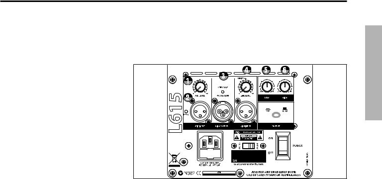
1. MIC LEVEL (L612 and L615 only)
The L612 and L615’s MIC LEVEL controls the overall level of the microphone input. Raise the MIC Level to adjust the volume of the microphone connected to the MIC input.
IMPORTANT NOTE!!: Be sure to keep the MIC LEVEL control all the way off if there is no microphone connected.
2. PEAK LED
The PEAK LED will illuminate RED when the LIVE series Mic
or Line input is receiving a clipped signal. If the PEAK LED lights up, lower the Mic or Line Level control. Once the PEAK LED goes off, raise the level controls back up until just before the PEAK LED lights.
3. DYNAMIC PROTECTION
The AMP / CLIP LED is a dual color LED used to monitor the output of the LIVE Series’ internal power amplifiers. When the unit is first powered on, the AMP / CLIP LED will light red (indicating the output relay is open). After the soft-start circuitry activates and the output relay closes, the AMP / CLIP will change to bright green indicating the unit is ready for operation. The LED will flash red on signal power peaks, while the green LED is still on. If there is a failure condition, the output relay opens and the LED will switch to solid red, indicating a fault. If this happens, contact your authorized Samson Audio Service Center.
4. LINE LEVEL
The LIVE Series’ LINE LEVEL controls the overall level of the LINE input. Raise the LINE Level to adjust the volume of the signal connected to the LINE input.
Using the Equalizer Section (L612, L612M and L615 only)
The L612, L612M and L615 input channels feature a 2-band equalizer allowing you to adjust the high and low frequencies independently. The channel’s frequency response is flat when the knobs are in the "12:00" position. You can set a “music” curve by adding a little boost to both the LOW and HIGH frequency. When using the L612M as a vocal monitor, try a little cut on the LOW and HIGH frequency to remove unwanted bass and treble for a more focused mid-range response. For most applications, it’s best to start with the LOW and HIGH controls set flat (12:00 position) and then use the HIGH and LOW EQ in small amounts until you reach the sound you want.
5. LOW
Rotating the LOW knob towards the right will boost the bass frequencies at 100Hz by 12dB, and rotating it towards the left will cut the bass frequencies at 100Hz by 12dB.
6. HIGH
Rotating the HIGH knob towards the right will boost the treble frequencies at 10kHz by 12dB, and rotating it towards the left will cut the treble frequencies at 10kHz by 12dB.
ENGLISH
ENGLISH
Operating the Live Series
Controls and Functions - continued
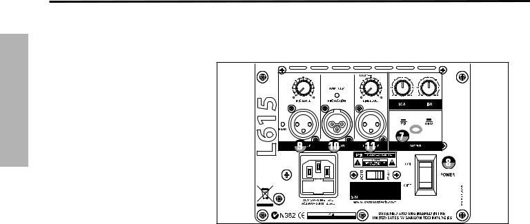
7. OUTPUT SWITCH
The Output switch is used to select the signal that is sent to
the Line Output. You can have either a parallel output directly from the Line input, or a mixed signal including the Mic
and line inputs plus the EQ and limiter. When the switch
is in the up position, the signal on the Line Output is exactly the same as the signal on the Line Input. When the switch is in the down position, the Line Output carries the MIX of the Mic and Line Inputs. If
the Level controls, High and Low Equalizer and Filter are used, they will also affect the signal sent to the Line Output.
8. POWER SWITCH
Each Live Series enclosure has a main POWER switch to activate the system. It’s a good idea to keep the POWER switch, and INPUT LEVEL controls, set to their off positions before you install the IEC power cable. Connect the supplied AC cable to the AC inlet on the rear amplifier panel. Be sure you have
a good AC power connection, and then, set the POWER switch to the “ON” position. The LIVE series amplifiers feature a “soft start” circuit to protect the amplifier from potentially damaging inrush current. In order to ensure that the soft start circuit is working properly, be sure to avoid turning the POWER switch on and off too quickly.
Input and Output Connectors
9. MIC XLR Input (L612 and L615 only)
The Live Series’ microphone input accepts a standard low impedance (150-600 Ohms) input and the connection is made via a standard female XLR connector. The microphone input features a high quality, discrete transistor pre-amp providing transparency and extended dynamic range. The MIC input can work simultaneously with the LINE input so it is possible to use a microphone while playing alone with a keyboard that is plugged into the Live Series’s LINE input. You can control the microphone input by using the MIC LEVEL control as described in the section below.
10. LINE OUTPUT
You can run several cabinets by using the LINE OUTPUT to daisy-chain one Live Series to another. The LINE OUTPUT is a balanced output that, depending on the position of the OUTPUT switch, will have either a direct parallel output of the Line input, or the Mix of the Line and Mic input. For more information on the Output switch, see section 7 above. For more information on cables and wiring, see page 13 of
this manual for a detailed wiring diagrams.
º
11. LINE Balanced Input
The Live Series speakers employ an XLR connector that accepts a standard XLR mic cable for balanced line level signals. The LINE input can work simultaneously with the Mic input so it is possible to use a microphone while playing alone with a keyboard that is plugged into the Live Series’s LINE input. You can control the LINE input by using the LINE LEVEL control as described in the previous page. For more information on cable and wiring, see page 13 of this manual for a detailed wiring diagrams.
10
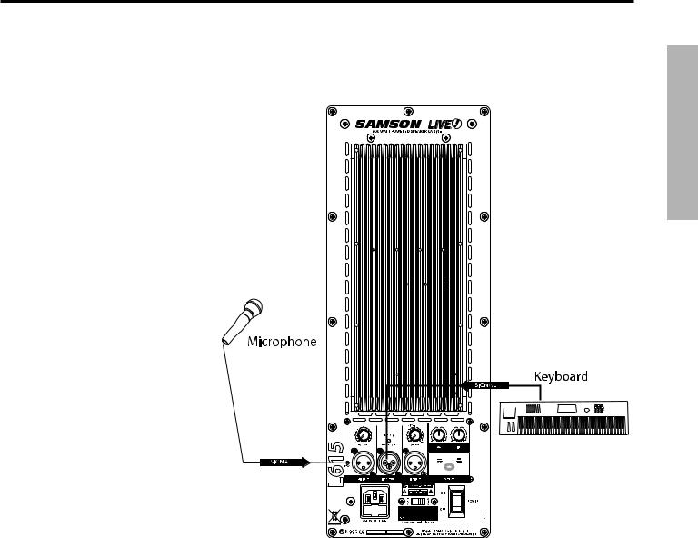
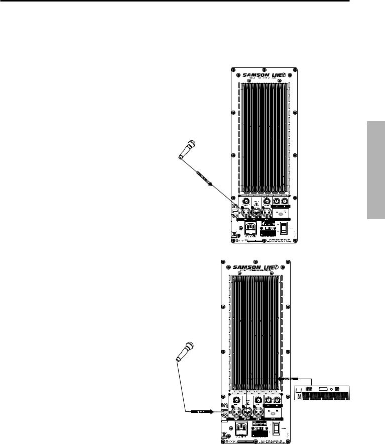
L612 and L615 Compact
Lounge PA for Two
This example shows a PA system set-up that can be used for a small club, at a ceremony or in a lounge, using a single Live Series for both a microphone and vocal. A separate signal is sent from the vocal microphone to the L612 or L615’s Mic input, and from the keyboard to the Live Series’ Line input. The individual Mic and Line level controls allow you to create a mix right on the Live Series. For further control, you can use the Live Series’ two-band equalizer to boost or cut the highs and/or low frequencies  adjusting the overall tonal contour of the system.
For more information on cable and wiring, see page 13 of this manual
for a detailed wiring diagrams.
Live Series System Set-ups
ENGLISH
11
ENGLISH |
|
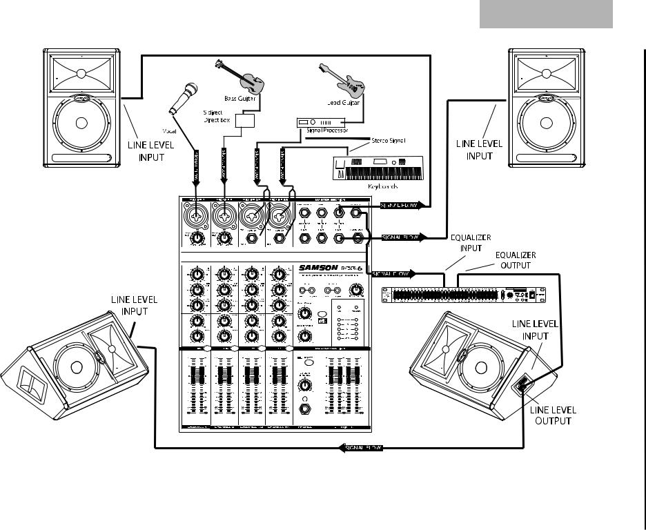
Monitors With System PA Band Live |
Set System Series Live |
|
ups- |
12 |
|
This example shows a typical PA system using mixer with a pair of Live Series for the main left and right mix. A separate signal from the mixer’s AUX/MONITOR bus is sent to two additional Live Series monitors. In order to increase the output of the monitor system, the use of an external graphic equalizer like one of the Samson “D Class” or “S curve” series is highly recommended.
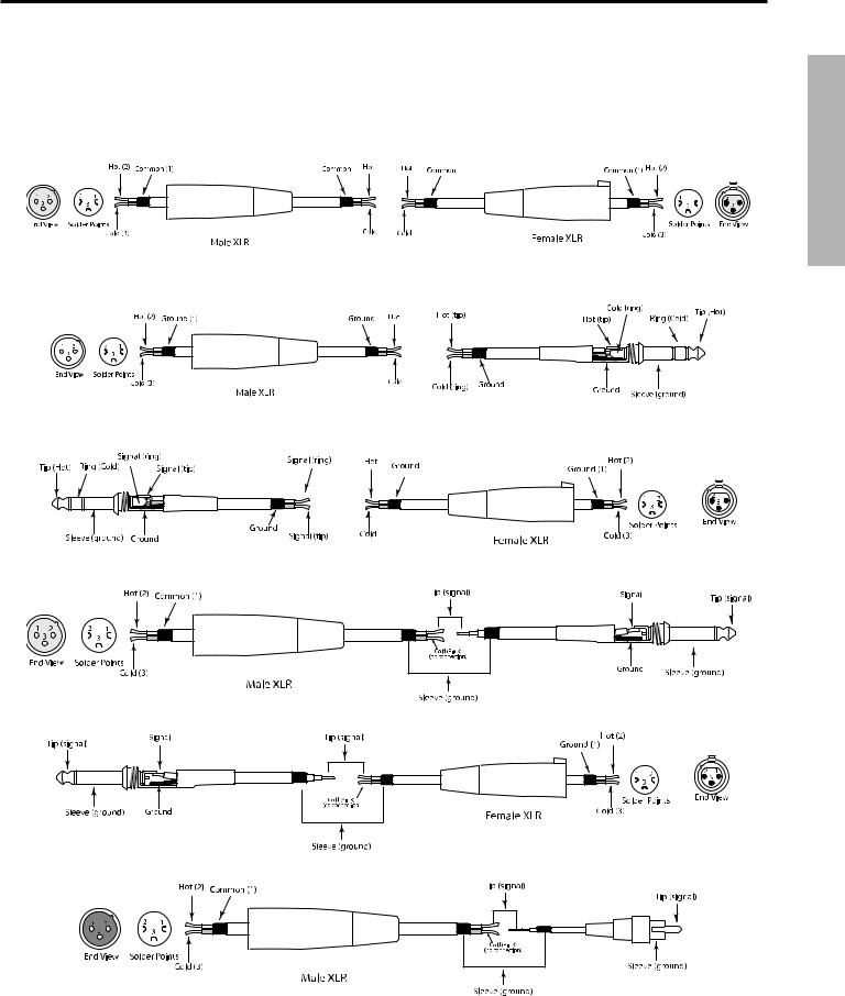
LIVE! Series Wiring Guide
Connecting The Live Series
The are several ways to interface the Live Series to support a variety of applications. The Live Series features balanced inputs and outputs, so connecting balanced and unbalanced signals is possible.
XLR to XLR Balanced
XLR to Balanced 1/4-Inch
Balanced 1/4” Connector to Female XLR
Unbalanced Male XLR to1/4” Connector
Unbalanced 1/4” Connector to Female XLR
Unbalanced XLR Connector to RCA
ENGLISH
13

FRANÇAIS
Introduction
Merci d’avoir choisi les enceintes actives de la série Live de Samson ! Équipées d’amplificateurs garantissant une puissance et une clarté sonore exceptionnelles, de circuits de traitement actifs très sophistiqués et
de composants de haut-parleurs et de baffle de haute qualité, les enceintes Live offrent un son de qualité optimale et sont adaptées à toutes les applications de sonorisation. La série Live comprend cinq enceintes, L612, L612M, L615, L1212 et L1215, et ce mode d’emploi regroupe les instructions d’utilisation et les caractéristiques de chacune d’entre elles. Le baffle de forme trapézoïdale des L612, L615, L1212 et L1215 permet de les utiliser comme enceinte de façade, alors que les L612M sont conçues pour servir de retours de scène. Les L612 , L612M et L1212 sont des enceintes 2 voies actives munies d’un ou deux Woofers haute puissance de 30,5 cm (12 pouces) de conception spéciale et d’un Tweeter à dôme en titane de 4,4 cm, couplé à un pavillon à directivité constante de 2,5 cm d’embouchure. Les L615 et L1215 sont des enceintes 2 voies actives équipées d’un ou deux Woofers haute puissance de 38,1 cm (15 pouces) de conception spéciale et d’un Tweeter à dôme en titane de 4,4 cm, couplé à un pavillon à directivité constante de 2,5 cm d’embouchure. Les L612, L612M et L615 sont munies d’un module de bi-amplification intégré (300 Watts) offrant une puissance de 250 Watts pour le Woofer, et de 50 Watts pour le Tweeter. Les L1212 et L1215 disposent d’une puissance impressionnante de 400 Watts pour leurs deux Woofers, et de 100 Watts pour leur Tweeter. Tous les amplificateurs des enceintes de la série Live sont dotés d’un filtre de coupure actif intégré et d’un circuit de traitement de la dynamique multibandes. Les L612 et L615 offrent une section de préamplification pratique (en face arrière), qui comporte des entrées micro/ligne et des réglages de niveau individuels, comme les consoles de mixage. De plus, ces enceintes proposent un égaliseur 2 bandes et d’un réglage permettant de sélectionner le signal acheminé à la sortie d’extension. Les enceintes de la série Live sont aussi parfaitement adaptées aux applications de studio grâce à la fonction de traitement Optimax exclusive à Samson, qui utilise des circuits sophistiqués pour compresser et limiter le signal afin d’offrir un niveau de sortie optimal. Ceci permet aux enceintes Live de générer des niveaux sonores très élevés sans compromettre la qualité de restitution des basses fréquences. La forme trapézoïdale de leur baffle garantit
une qualité sonore supérieure lorsque les Live servent d’enceintes de façade, et elle permet également de les utiliser en retours de scène. Grâce à leur amplificateur intégré, l’installation et le démontage des enceintes Live s’effectuent très rapidement. Les enceintes L612 et L615 sont pourvues d’une embase pour pied intégrée de 35 mm permettant de les monter facilement sur pied. La grille en acier robuste et le revêtement moquetté résistant assurent la protection de l’enceinte en tournée. En utilisant un amplificateur intégré et des composants de haute précision, les enceintes de la série Live peuvent offrir une qualité sonore cristalline et une dispersion sonore étendue. Vous pouvez ainsi bénéficier de hautes fréquences limpides, douces et ciselées, et de basses fréquences puissantes, précises et prononcées. Qu’elles soient utilisées en sonorisation fixe ou en sonorisation mobile, les enceintes de la série Live répondent aux besoins des artistes et des professionnels du son nécessitant un système de sonorisation puissant et de qualité professionnelle.
Dans ces pages, vous trouverez une description détaillée de toutes les caractéristiques des enceintes Live, la description des faces avant et arrière, les instructions d’utilisation et les caractéristiques techniques. Vous trouverez également une carte de garantie : n’oubliez pas de la remplir et de nous l’envoyer pour pouvoir bénéficier de l’assistance technique en ligne et recevoir les informations sur les produits Samson. Pensez également à visiter notre site (www.samsontech.com) pour obtenir des informations sur tous nos produits.
Avec un entretien adapté et une ventilation suffisante, votre enceinte vous donnera satisfaction pendant de nombreuses années. Veuillez noter le numéro de série et la date d'achat pour toute référence ultérieure.
Numéro de série :_______________________________
Date d'achat :____________________________
Pour faire réparer votre enceinte, vous devez d'abord obtenir un numéro d'autorisation de retour auprès de nos services. Sans ce numéro, nous ne pouvons pas accepter le produit. Si vous avez acheté le produit aux USA, appelez Samson au 1-800-3SAMSON (1-800-372-6766) pour obtenir un numéro de retour avant de nous le renvoyer. Veuillez si possible conserver le matériel d’emballage afin de l’utiliser en cas de retour. Si vous avez
acheté le produit hors des USA, contactez votre revendeur Samson. 14
Série Live - Caractéristiques
La série Live propose des enceintes deux voies actives complètes parfaitement adaptées à la plupart des applications de sonorisation. Voici quelques-unes de leurs caractéristiques principales :
•Enceintes deux voies bi-amplifiées de qualité professionnelle.
•Les enceintes de la série LIVE sont équipées de Woofers haute puissance de conception spéciale. Les L612 et L612M disposent d’un Woofer de 30,5 cm (12 pouces), les L1212, de deux Woofers de 30,5 cm, les L615, d’un Woofer de 38,1 cm (15 pouces), et les L1215, de deux Woofers de 38,1 cm. Tous les Woofers sont munis de bobines et d’aimants surdimensionnés.
•Tweeter à dôme en titane de 4,4 cm, couplé à un pavillon à directivité constante de 2,5 cm d’embouchure, garantissant une réponse précise dans les hautes fréquences.
•Les L612, L612M et L615 offrent une puissance totale de 300 Watts grâce à leurs amplificateurs (Classe AB) de 250 Watts pour le Woofer et de 50 Watts pour le Tweeter. Les amplificateurs des L1212 et L1215 peuvent délivrer une puissance de 400 Watts aux deux Woofers, et de 100 Watts au Tweeter.
•Toutes ces enceintes possèdent une entrée ligne symétrique avec réglage de niveau (LEVEL) et indicateur d’écrêtage (PEAK).
•Les L612 et L615 sont équipées d’une entrée micro symétrique avec réglage de niveau, alimentation fantôme (pour l’utilisation de micros à condensateur), réglages de niveaux séparés pour les hautes/basses fréquences et filtre coupe-bas sélectionnable.
•Les amplificateurs de puissance des enceintes de la série LIVE disposent d’un radiateur et de transformateurs de puissance de grande taille.
•Processeur de traitement multibandes sophistiqué offrant une limitation inaudible.
•Filtre de coupure intégré (24 dB/octave) avec alignement temporel.
•Circuit de protection multi-points pour l’amplificateur, avec LED servant à indiquer les irrégularités.
•Les L612 et L615 peuvent être montées sur un pied grâce à leur embase 35 mm standard.
•Baffles en contreplaqué garantissant une puissance maximale et une fiabilité à toute épreuve en tournée.
•Garantie étendue de trois ans.
FRANÇAIS
15
Composants des L612 et L615
FRANÇAIS
1.Tweeter à compression – Tweeter à dôme en titane de 44 mm avec embouchure de 25 mm.
2.Pavillon – Pavillon à directivité constante (60°x90°) de 25 mm d’embouchure garantissant une dispersion étendue et une réponse hors-axe linéaire.
3.Woofer - Woofer haute puissance de 30,5 cm
(12 pouces) ou 381 mm (15 pouces) avec aimant de grande taille et bobine de 7,6 cm, conçu pour offrir une réponse étendue et précise dans les basses fréquences.
4.LED d’alimentation – La Led s’allume en bleu lorsque l’enceinte est sous tension et prête à l’utilisation.
5.Poignée – Une des deux poignées surdimensionnées.
6.Grille acier – Grille de protection en acier robuste permettant d’accéder facilement au Woofer.
7.Évent– Évent accordé servant à étendre la réponse dans les basses fréquences.
8.Baffle – Baffle en contreplaqué robuste offrant une puissance maximale et une fiabilité à toute épreuve.
Face arrière de l’amplificateur
9.Radiateur - Le refroidissement par convection de l’amplificateur est assuré par un radiateur surdimensionné en aluminium extrudé.
10.LED PEAK - Cette Led s’allume lorsque le signal de l’entrée micro produit de l’écrêtage.
11.MIC LEVEL – Détermine le niveau de l’entrée micro.
12.LED AMP/CLIP - Cette Led deux couleurs s’allume en vert lorsque l’amplificateur est activé, elle clignote en rouge lorsqu’il produit une surcharge et elle s’allume en rouge lorsque le circuit de protection est activé.
16
13.LINE LEVEL – Détermine le niveau de l’entrée ligne.
14.LOW FREQUENCY - Ce réglage détermine le niveau des basses fréquences. Il permet jusqu’à 12 dB d’atténuation/accentuation à 100 Hz.
15.HIGH FREQUENCY - Ce réglage détermine le niveau des hautes fréquences. Il permet jusqu’à 12 dB d’atténuation/accentuation à 10 kHz.
16.Touche OUTPUT - Cette touche permet de sélectionner le signal acheminé à la sortie ligne. Lorsqu’elle est en position relevée, le signal de la sortie ligne est identique à celui connecté à l’entrée. Lorsqu’elle est en position basse, la sortie ligne délivre un mélange des signaux micro et ligne affectés par les filtres grave et aigu.
17.Interrupteur POWER – Cet interrupteur secteur permet de mettre l’enceinte sous tension.
18.Sélecteur VOLTAGE - Utilisez ce réglage pour sélectionner la tension d’utilisation (115 à 230 V).
REMARQUE IMPORTANTE ! Assurez-vous d’utiliser un fusible dont le calibre correspond à la tension sélectionnée (voir les valeurs indiquées sous l’embase secteur).
19.Connecteur LINE INPUT - Cette entrée XLR permet la connexion de signaux à niveau ligne symétriques.
20.Embase secteur/support de fusible – Connectez le cordon secteur standard fourni à cette embase.
21.Connecteur LINE OUTPUT - Ce connecteur XLR mâle sert à relier plusieurs enceintes LIVE.
22.Connecteur MIC INPUT - Cette entrée XLR permet la connexion des micros faible impédance au préampli faible bruit avec alimentation fantôme.
Composants des L1212 et L1215
FRANÇAIS
1.Tweeter à compression – Tweeter à dôme en titane de 44 mm avec embouchure de 25 mm.
2.Pavillon – Pavillon à directivité constante (60°x90°) de 25 mm d’embouchure garantissant une dispersion étendue et une réponse hors-axe linéaire.
3.LED d’alimentation – La Led s’allume en bleu lorsque l’enceinte est sous tension et prête à l’utilisation.
4.Woofers - Woofers haute puissance de 30,5 cm
(12 pouces) ou 381 mm (15 pouces) avec bobines et aimants de grande taille, conçus pour offrir une réponse étendue et précise dans les basses fréquences.
5.Poignée – Une des deux poignées surdimensionnées.
6.Évent– Évent accordé servant à étendre la réponse dans les basses fréquences.
7.Grille acier – Grille de protection en acier robuste permettant d’accéder facilement aux Woofers.
8.Baffle – Baffle en contreplaqué robuste offrant une puissance maximale et une fiabilité à toute épreuve.
Face arrière de l’amplificateur
9.Radiateur - Le refroidissement par convection de l’amplificateur est assuré par un radiateur surdimensionné en aluminium extrudé.
10.Connecteur LINE INPUT - Cette entrée XLR permet la connexion de signaux à niveau ligne symétriques.
11.Connecteur LINE OUTPUT - Ce connecteur XLR mâle sert à relier plusieurs enceintes LIVE.
12.LED AMP/CLIP - Cette Led deux couleurs s’allume en vert lorsque l’amplificateur est activé, elle clignote en rouge lorsqu’il produit une surcharge et elle s’allume en rouge lorsque le circuit de protection est activé.
13.LINE LEVEL – Détermine le niveau de l’entrée ligne.
14.Interrupteur POWER – Cet interrupteur secteur permet de mettre l’enceinte sous tension.
15.Sélecteur VOLTAGE - Utilisez ce réglage pour sélectionner la tension d’utilisation (115 à 230 V).
REMARQUE IMPORTANTE ! Assurez-vous d’utiliser un fusible dont le calibre correspond à la tension sélectionnée (voir les valeurs indiquées sous l’embase secteur).
16.Embase secteur/support de fusible – Connectez le cordon secteur standard fourni à cette embase.
17
Composants des L612M
FRANÇAIS
1.Baffle – Baffle en contreplaqué robuste offrant une puissance maximale et une fiabilité à toute épreuve.
2.Poignée – Poignée de transport surdimensionnée.
3.Évent– Évent accordé servant à étendre la réponse dans les basses fréquences.
4.Grille acier – Grille de protection en acier robuste.
5.Woofer - Woofer haute puissance de 30,5 cm
(12 pouces) avec aimant de grande taille et bobine de 7,6 cm, conçu pour offrir une réponse étendue et précise dans les basses fréquences.
6. LED d’alimentation – La Led s’allume en bleu lorsque l’enceinte est sous tension et prête à l’utilisation.
7Tweeter à compression – Tweeter à dôme en titane de 44 mm avec embouchure de 25 mm.
8.Pavillon – Pavillon à directivité constante (60°x90°) de 25 mm d’embouchure garantissant une dispersion étendue et une réponse hors-axe linéaire.
Face arrière de l’amplificateur
9.Embase secteur/support de fusible – Connectez le cordon secteur standard fourni à cette embase.
10.Sélecteur VOLTAGE - Utilisez ce réglage pour sélectionner la tension d’utilisation (115 à 230 V).
REMARQUE IMPORTANTE ! Assurez-vous d’utiliser un fusible dont le calibre correspond à la tension sélectionnée (voir les valeurs indiquées au-dessus de l’embase secteur).
11.Interrupteur POWER – Cet interrupteur secteur permet de mettre l’enceinte sous tension.
12.Radiateur - Le refroidissement par convection de l’amplificateur est assuré par un radiateur surdimensionné en aluminium extrudé.
Face latérale de l’amplificateur
13.LED AMP/CLIP - Cette Led deux couleurs s’allume en vert lorsque l’amplificateur est activé, elle clignote en rouge lorsqu’il produit une surcharge et elle s’allume en rouge lorsque le circuit de protection est activé.
14.LINE LEVEL – Détermine le niveau de l’entrée ligne.
15.LOW FREQUENCY - Ce réglage détermine le niveau des basses fréquences. Il permet jusqu’à 12 dB d’atténuation/accentuation à 100 Hz.
16.HIGH FREQUENCY - Ce réglage détermine le niveau des hautes fréquences. Il permet jusqu’à 12 dB d’atténuation/accentuation à 10 kHz.
17.Connecteur LINE INPUT - Cette entrée XLR permet la connexion de signaux à niveau ligne symétriques.
18.Connecteur LINE OUTPUT - Ce connecteur XLR mâle sert à relier plusieurs enceintes L612M.
18
Configuration rapide des L612 et L615
Dans les pages qui suivent, vous trouverez des descriptions détaillées de tous les réglages et composants des enceintes de la série Live. Vous pouvez aussi suivre cette procédure de prise en main pour utiliser les L612 et L615 plus rapidement.
Utilisation d’un micro
• Assurez-vous que l’interrupteur secteur de l’enceinte soit réglé sur OFF.
• Tournez les boutons LINE et MIC LEVEL complètement à gauche (au minimum).
• Connectez le cordon secteur à une prise secteur.
• Connectez un micro à l’entrée MIC INPUT de |
Micro |
l’enceinte en vous servant d’un câble XLR |
|
standard. |
|
• Réglez l’interrupteur secteur de l’enceinte sur ON.
• Parlez dans le micro et montez progressivement le réglage MIC LEVEL jusqu’à ce que vous obteniez le niveau souhaité.
Utilisation d’une source à niveau ligne
• Assurez-vous que l’interrupteur secteur de l’enceinte soit réglé sur OFF.
• Tournez les boutons LINE et MIC LEVEL complètement à gauche (au minimum).
• Connectez le cordon secteur à une prise secteur.
• Reliez une source à niveau ligne, comme une console ou un clavier, à l’entrée LINE INPUT de l’enceinte en vous servant d’un câble XLR standard.
• Réglez l’interrupteur secteur de l’enceinte sur ON.
• Activez la source du signal (exemple : un |
Micro |
|
Clavier |
||
lecteur de CD), puis montez progressivement |
le réglage LINE LEVEL jusqu’à ce que vous
obteniez le niveau souhaité.
REMARQUE IMPORTANTE !! : Veillez à ce que le réglage MIC LEVEL soit au minimum lorsque aucun micro n’est connecté.
REMARQUE IMPORTANTE !! : Veillez à ce que la Led PEAK ne s’allume pas régulièrement en rouge. Vous risquez d’endommager l’enceinte
si vous l’utilisez pendant que la Led PEAK est allumée en rouge. Vous devez réduire le niveau de sortie de la console ou le réglage LINE LEVEL de façon à ce que la Led PEAK ne s’allume en rouge qu’occasionnellement.
FRANÇAIS
19
 Loading...