


 Loading...
G R A P H I C
EQUALIZER
SAMSON®
E62i/E31i/E30i GRAPHIC EQUALIZER
Table of Contents
ENGLISH
Introduction 1
System Features 2
Guided Tour 3
Front Panel 3
Rear Panel 6
System Configurations 8
Setting Up and Using the E62i / E31i / E30i 10 About Equalization 12
Grounding Techniques 14
Using A Patchbay 15
Using the E62i / E31i / E30i with an RTA 16
Using the E62i / E31i to “Ring Out” A Monitor System 17
Appendix A: Pass-Band Graphs 45
Specifications 46
FRANCAIS
Introduction 18
Fonctions 19
Visite guidée 20
Face avant 20
Face arrière 23
Réglages et utilisation du E62 i / E31i / E30i 25 Appendix A: Pass-Band Graphs 45 Spécifications 46
DEUTSCHE
Einleitung 27 System-Merkmale 28
Übersicht 29
Vorderseite 29 Rückseite 32
Einstellungen und Einsatz des E62i / E31i / E30i 34
Appendix A: Pass-Band Graphs 45
Technische Daten 46
ESPANOL
Introducción 36
Características del Sistema 37
Recorrido guiado 38 Panel frontal 38
Panel trasero 41
Ajuste y funcionamiento del E62i / E31i / E30i 43
Appendix A: Pass-Band Graphs 45
Especificaciones 46
Produced by On The Right Wavelength for Samson Technologies Corp.
Copyright 1998, 1999, Samson Technologies Corp.
Printed August, 1999
Samson Technologies Corp.
575 Underhill Blvd.
P.O. Box 9031
Syosset, NY 11791-9031
Phone: 1-800-3-SAMSON (1-800-372-6766)
Fax: 516-364-3888

Introduction
Congratulations on purchasing the Samson E62i 1/3 Octave Stereo 31 Band, E31i 1/3
Octave Mono 31 Band Equalizer or E30i 2/3 Octave Stereo 15 Band Constant Q Graphic
Equalizer! Although these products are designed for easy operation, we suggest you take some time out first to go through these pages so you can fully understand how we’ve implemented a number of unique features.
The E62i, E31i and E30i are all professional quality signal processors that give you precise tonal control over one or two channels of audio. Center detented sliders allow you to selectively cut or boost selected frequency areas by as much as 12 dB. Front panel controls include output level sliders and bypass switches and LEDs, while the rear panel provides electronically balanced inputs and outputs. All three models can be used in a wide variety of applications, including live performance (in conjunction with either Front Of
House or monitor mixers), in broadcast environments, or for recording.
In this manual, you’ll find a more detailed description of the features of the E62i, E31i and
E30i, as well as a guided tour through their front and rear panels, step-by-step instructions for using the units, suggested applications for use with a patch bay, a Real Time Analyzer
(RTA) or for ringing out monitor systems, reference appendices, and full specifications.
You’ll also find a warranty card enclosed—please don’t forget to fill it out and mail it so that you can receive online technical support and so we can send you updated information about other Samson products in the future. Also, be sure to check out our website
(http://www.samsontech.com) for complete information about our full product line.
SPECIAL NOTE: Should your unit ever require servicing, a Return Authorization number (RA) is necessary. Without this number, the unit will not be accepted. If purchased in the United States, please call Samson at 1-800-372-6766 for a Return Authorization number prior to shipping your unit. Please retain the original packing materials and, if possible, return the unit in its original carton and packing materials. If purchased outside of the United States, please contact your local distributor for warranty information.
ENGLISH
1

System Features
ENGLISH
The Samson E62i, E31i and E30i Graphic Equalizers all utilize state-of-the-art technology in audio signal processing. Here are some of their main features:
•In the E62i and E31i, 31 bands of equalization, with each frequency band representing 1/3 of an octave in the 20 Hz to 20 kHz range; in the E30i, 15 bands of equalization, with each frequency band representing 2/3 of an octave in the 25 Hz to 16 kHz range.
•Constant Q circuitry ensures that the bandwidth of the selected frequency area stays the same even when approaching maximum boost or attenuation. As a result, phase shifting and intermodulation distortion is greatly reduced, making for pristine sound.
•In the E62i and E31i, 6 or 12 dB of gain and attenuation for each of the frequency bands, allowing both fine and coarse adjustment of the equalization curve. In the E30i, 12 dB of gain and attenuation for each of the frequency bands
•Ultra-low noise circuity ensures superb audio fidelity.
•Switchable 80 Hz High Pass Filter (HPF) for removing rumble and floor noise.
•In the E62i and E3ii, a Cut Only control for fast, easy notched feedback removal.
•Electronically balanced inputs and outputs.
•In the E62i and E30i, dual channel operation for processing either a stereo signal or two independent monophonic signals.
•Front panel hard-wired Bypass switches (with dedicated Bypass LEDs) allow the equalization circuitry and output level control to be activated or deactivated.
•Level controls enable output signals to be attenuated or boosted for optimum signal-to-noise ratio.
•Peak indicator LEDs light 5 dB prior to clipping.
•Relay power-on circuitry prevents speaker “thumps” when the unit is turned on.
•Internal power supply ensures reliability and trouble-free operation.
•Standard 19" rack design (the E62i takes just two rack spaces, while the E31i and E30i require only a single rack space) for easy integratation into any traveling or fixed installation audio system.
•Optional security cover kit prevents EQ settings from accidentally being altered.
•All-steel chassis makes the E62i / E31i / E30i eminently road-worthy.
2
|
Guided Tour - E62i / E31i / E30i |
|
|||||||||||||||||||||||||||||||||||
|
|
|
|
|
|
|
|
|
|
|
|
|
|
|
|
|
|
|
|
|
|
|
|
|
|
|
|
Front Panel |
|
||||||||
|
|
|
|
|
|
|
|
|
|
|
|
|
|
|
|
|
1 |
|
|
|
|
|
|
|
|
|
|
|
|
|
|
2 |
3 |
|
|
|
ENGLISH |
|
|
|
|
|
|
|
|
|
|
|
|
|
|
|
|
|
|
|
|
|
|
|
|
|
|
|
|
|
|
|
|
|
4 |
|
|
6 |
|
|
|
|
|
|
|
|
|
|
|
|
|
|
|
|
|
|
|
|
|
|
|
|
|
|
|
|
|
|
|
|
|
|
|
|
|
||
|
GRAPHIC EQUALIZER E62i 1/3 OCTAVE DUAL 31 BAND CONSTANT Q |
|
|
|
|
|
|
|
3.15KHz |
|
|
|
|
|
|
|
|
SAMSON |
|
7 |
|||||||||||||||||
|
20Hz |
25Hz |
31.5Hz |
40Hz |
50Hz |
63Hz |
80Hz |
100Hz |
125Hz |
160Hz |
200Hz |
250Hz |
315Hz |
400Hz |
500Hz |
630Hz |
800Hz |
1KHz |
1.25KHz |
1.6KHz |
2KHz |
2.5KHz |
4KHz |
5KHz |
6.3KHz |
8KHz |
10KHz |
12.5KHz |
16KHz |
20KHz |
|
|
|
|
|||
|
|
|
|
|
|
|
|
|
|
|
|
|
|
|
|
|
|
|
|
|
|
|
|
|
|
|
|
|
|
|
|
|
|
± 12dB |
|
||
|
+12dB |
|
|
|
|
|
|
|
|
|
|
|
|
|
|
|
|
|
|
|
|
|
|
|
|
|
|
|
|
|
|
+12dB |
+6dB |
|
|
||
|
|
|
|
|
|
|
|
|
|
|
|
|
|
|
|
|
|
|
|
|
|
|
|
|
|
|
|
|
|
|
|
|
PEAK |
|
|
|
|
CH |
0dB |
|
|
|
|
|
|
|
|
|
|
|
|
|
|
|
|
|
|
|
|
|
|
|
|
|
|
|
|
|
|
0dB |
0dB |
CUT |
|
8 |
|
A |
|
|
|
|
|
|
|
|
|
|
|
|
|
|
|
|
|
|
|
|
|
|
|
|
|
|
|
|
|
|
ONLY |
|
|||||
|
|
|
|
|
|
|
|
|
|
|
|
|
|
|
|
|
|
|
|
|
|
|
|
|
|
|
|
|
|
|
|
|
|
|
|||
|
|
|
|
|
|
|
|
|
|
|
|
|
|
|
|
|
|
|
|
|
|
|
|
|
|
|
|
|
|
|
|
|
BYPASS |
|
|
||
|
-12dB |
|
|
|
|
|
|
|
|
|
|
|
|
|
|
|
|
|
|
|
|
|
|
|
|
|
|
|
|
|
|
-12dB |
∞ |
HPF |
|
||
|
20Hz |
25Hz |
31.5Hz |
40Hz |
50Hz |
63Hz |
80Hz |
100Hz |
125Hz |
160Hz |
200Hz |
250Hz |
315Hz |
400Hz |
500Hz |
630Hz |
800Hz |
1KHz |
1.25KHz |
1.6KHz |
2KHz |
2.5KHz |
3.15KHz |
4KHz |
5KHz |
6.3KHz |
8KHz |
10KHz |
12.5KHz |
16KHz |
20KHz |
LEVEL |
|
|
|
|
|
|
+12dB |
|
|
|
|
|
|
|
|
|
|
|
|
|
|
|
|
|
|
|
|
|
|
|
|
|
|
|
|
|
|
+12dB |
+6dB |
± 12dB |
|
6 |
|
|
|
|
|
|
|
|
|
|
|
|
|
|
|
|
|
|
|
|
|
|
|
|
|
|
|
|
|
|
|
|
|
|
|
||||
|
|
|
|
|
|
|
|
|
|
|
|
|
|
|
|
|
|
|
|
|
|
|
|
|
|
|
|
|
|
|
|
|
PEAK |
|
|
|
|
CH |
0dB |
|
|
|
|
|
|
|
|
|
|
|
|
|
|
|
|
|
|
|
|
|
|
|
|
|
|
|
|
|
|
0dB |
0dB |
CUT |
|
|
|
B |
|
|
|
|
|
|
|
|
|
|
|
|
|
|
|
|
|
|
|
|
|
|
|
|
|
|
|
|
|
|
ONLY |
|
|
||||
|
|
|
|
|
|
|
|
|
|
|
|
|
|
|
|
|
|
|
|
|
|
|
|
|
|
|
|
|
|
|
|
|
BYPASS |
|
|
|
|
|
-12dB |
|
|
|
|
|
|
|
|
|
|
|
|
|
|
|
|
|
|
|
|
|
|
|
|
|
|
|
|
|
|
-12dB |
∞ |
HPF |
|
7 |
|
|
20Hz |
25Hz |
31.5Hz |
40Hz |
50Hz |
63Hz |
80Hz |
100Hz |
125Hz |
160Hz |
200Hz |
250Hz |
315Hz |
400Hz |
500Hz |
630Hz |
800Hz |
1KHz |
1.25KHz |
1.6KHz |
2KHz |
2.5KHz |
3.15KHz |
4KHz |
5KHz |
6.3KHz |
8KHz |
10KHz |
12.5KHz |
16KHz |
20KHz |
|
|
|
|
|
|
|
|
|
|
|
|
|
|
|
|
|
|
|
|
|
|
|
|
|
|
|
|
|
|
|
|
|
|
|
|
|
|
|
|
|
|
|
|
|
|
|
|
|
|
|
|
|
|
|
|
|
|
|
|
|
|
|
|
|
|
|
|
|
|
|
|
|
|
|
|
|
|
|
|
8 |
|
|
|
|
|
|
|
|
|
|
|
|
|
|
|
|
|
|
1 |
|
|
|
|
|
|
|
|
|
|
|
|
|
|
2 |
5 |
|
|
|
|
|
|
|
|
|
|
|
|
|
|
|
|
|
|
|
|
|
|
|
|
E62i |
|
|
|
|
|
|
|
|
|
|
|
|
|
|
|
||
|
|
|
|
|
|
|
|
|
|
|
|
|
|
|
|
|
|
|
1 |
|
|
|
|
|
|
|
|
|
|
|
|
|
2 |
3 |
4 |
6 |
|
GRAPHIC EQUALIZER |
E31i 1/3 OCTAVE 31 BAND CONSTANT Q |
SAMSON |
20Hz 25Hz 31.5Hz 40Hz 50Hz |
63Hz 80Hz 100Hz 125Hz 160Hz 200Hz 250Hz 315Hz 400Hz 500Hz 630Hz 800Hz 1KHz 1.25KHz 1.6KHz 2KHz 2.5KHz 3.15KHz 4KHz |
5KHz 6.3KHz 8KHz 10KHz 12.5KHz 16KHz 20KHz |
+12dB |
+12dB |
+6dB |
± 12dB |
PEAK
0dB |
0dB |
0dB |
CUT |
||
|
|
ONLY |
BYPASS
-12dB |
-12dB |
∞ |
HPF |
20Hz |
25Hz |
31.5Hz |
40Hz |
50Hz |
63Hz |
80Hz |
100Hz |
125Hz |
160Hz |
200Hz |
250Hz |
315Hz |
400Hz |
500Hz |
630Hz |
800Hz |
1KHz |
1.25KHz |
1.6KHz |
2KHz |
2.5KHz |
3.15KHz |
4KHz |
5KHz |
6.3KHz |
8KHz |
10KHz |
12.5KHz |
16KHz |
20KHz |
5 
 8
8 
 7
7
|
|
|
E31i |
|
|
|
|
1 |
2 |
3 |
6 |
1 |
2 |
3 |
6 |
GRAPHIC EQUALIZER E30i 2/3 OCTAVE DUAL 15 BAND CONSTANT Q |
|
|
|
|
SAMSON |
|
|
25Hz 40Hz 63Hz 100Hz 160Hz 250Hz 400Hz 630Hz 1KHz 1.6KHz 2.5KHz |
4KHz 6.3KHz 10KHz 16KHz |
|
25Hz 40Hz |
63Hz 100Hz 160Hz 250Hz 400Hz 630Hz 1KHz 1.6KHz 2.5KHz |
4KHz 6.3KHz 10KHz 16KHz |
|
|
|
+12dB |
PEAK |
|
|
+12dB |
PEAK |
|
|
+6dB |
|
|
+6dB |
|
||
CH |
0dB |
HPF |
0dB |
HPF |
CH |
A |
|
+0dB |
|
+0dB |
B |
|
|
|
|
|
|
|
|
|
|
|
|
|
|
|
BYPASS |
|
|
|
|
|
|
|
|
|
|
|
|
|
|
|
BYPASS |
|
|
|
|
|
|
|
|
|
|
|
|
|
|
-12dB |
∞ |
|
|
|
|
|
|
|
|
|
|
|
|
|
|
-12dB |
∞ |
25Hz |
40Hz |
63Hz |
100Hz |
160Hz |
250Hz |
400Hz |
630Hz |
1KHz |
1.6KHz |
2.5KHz |
4KHz |
6.3KHz |
10KHz |
16KHz |
|
25Hz |
40Hz |
63Hz |
100Hz |
160Hz |
250Hz |
400Hz |
630Hz |
1KHz |
1.6KHz |
2.5KHz |
4KHz |
6.3KHz |
10KHz |
16KHz |
|
5 |
5 |
E30i
3

ENGLISH
Guided Tour - E62i / E31i / E30i
Front Panel
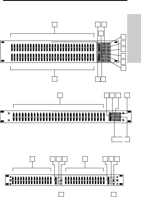
1: Equalizer sliders - Independent Equalizer sliders are provided for each frequency area (theE62i’ and E31i provide 31 frequency areas, while the E30i’ provides 15).
Calibration markings on either side of each Equalizer slider allow you to cut or boost each of frequency area. In the E62i and E30i, independent Equalizer sliders are provided for each of the two channels (Channel A and Channel B). As described below, the exact action of the Equalizer sliders depends upon the setting of the ±12 dB switch as well as, in the E62i and E31i, the setting of the Cut Only switch (see #4 and #7 on the next page).
In the E62i and E31i, when the Cut Only switch is not pressed in: When an Equalizer slider is at its center detented “0” position, the frequency area is unaffected (that is, there is no boost or cut). When moved all the way up (to the “+12 dB”) position, the frequency area is boosted by 12 dB (if the corresponding ±12 dB switch is pressed in) or 6 dB (if the corresponding ±12 dB switch is not pressed in). When moved all the way down (to the “-12 dB” position), the frequency area is attenuated by 12 dB (if the corresponding ±12 dB switch is pressed in) or 6 dB (if the corresponding ±12 dB switch is not pressed in).
In the E62i and E31i, when the Cut Only switch is pressed in: When an Equalizer slider is at its top-most position, the frequency area is unaffected (that is, there is no boost or cut), as indicated by the blue “0 dB” label. As the Equalizer slider is moved down, the frequency area is attenuated. As indicated by the blue “-6 dB” label, when the Equalizer slider is at its center detented position, the frequency area is attenuated by 6 dB (if the corresponding ±12 dB switch is not pressed in) or 12 dB (if the corresponding ±12 dB switch is pressed in). When moved all the way down (as indicated by the blue “-24 dB” label), the frequency area is attenuated by 12 dB (if the corresponding ±12 dB switch is not pressed in) or 24 dB (if the corresponding ±12 dB switch is pressed in).
In the E30i: When an Equalizer slider is at its center detented “0” position, the frequency area is unaffected (that is, there is no boost or cut). When moved all the way up (to the
“+12 dB”) position, the frequency area is boosted by 12 dB. When moved all the way down (to the “-12 dB” position), the frequency area is attenuated by 12 dB.
2:Level sliders - Use these to adjust the output level of signal leaving the E62i / E31i / E30i via its rear-panel output connectors (see #2 and #3 on page 7 for more information).
When a Level slider is at its center detented “0” position, the corresponding output signal is at unity gain (that is, there is no cut or boost). When a Level slider is moved all the way
up (to the “+6 dB”) position, the corresponding output signal is boosted by 6 dB. When a Level slider is moved all the way down (to the “∞ ” position), the corresponding output signal is infinitely attenuated (that is, there is no signal). In the E62i and E30i, independent Level sliders are provided for each of the two channels (Channel A and
Channel B). Note that the Level slider is deactivated when the E62i / E31i / E30i is in Bypass mode (see #5 on the following page).
3:Peak LEDs - Light steadily red whenever the corresponding input signal is within 5 dB of clipping. During normal operation, the Peak LED(s) should light only infrequently or not at all. In the E62i and E30i, independent Peak LEDs are provided for each of the two channels (Channel A and Channel B).
4

Guided Tour - E62i / E31i / E30i
Front Panel
4: Cut Only switches (E62i and E31i |
only) - When pressed in, the LED above the switch |
ENGLISH |
|
lights and all the Equalizer sliders serve to attenuate their frequency areas only (there is no |
|||
|
|||
boost) by up to 12 or 24 dB, depending upon the setting of the ±12 dB switch (see #7 |
|
||
below). The Cut Only switch should be used when you need to notch out certain |
|
||
frequencies in order to reduce feedback or “ring out” a room. See the “Ringing Out A |
|
||
Monitor System” section in this manual (page 17) for more information. In the E62i, |
|
||
independent Cut Only switches are provided for each of the two channels (Channel A and |
|
||
Channel B). |
|
|
|
5: Bypass switches - When pressed in, the LED to the left of the switch lights red and |
|
||
the equalization circuitry is made inactive so that the signal passes through unaffected, |
|
||
regardless of the settings of the Equalizer or Level sliders. When out (in the up position), |
|
||
the LED to the left of the switch lights green and the E62i equalization circuitry affects the |
|
||
signal as per the setting of the front panel Equalizer and Level sliders (see #1 and #2 on |
|
||
the previous page for more information). In the E62i and E30i, independent Bypass |
|
||
switches are provided for each of the two channels (Channel A and Channel B). |
|
||
6: HPF (High Pass Filter) switches - |
When pressed in, the LED to the left of the switch |
|
|
lights and an 80 Hz highpass filter is applied to the signal, effectively removing rumble and other low frequencies. In the E62i and E30i, independent HPF switches are provided for each of the two channels (Channel A and Channel B).
7: ±12 dB switches (E62i and E31i only) - When pressed in, the LED to the left of the switch lights and the Equalizer sliders cut or boost each frequency area by up to 12 dB, allowing coarse frequency curves to be set. When out (in the up position), the Equalizer sliders cut or boost each frequency area by up to 6 dB, allowing finer control and gentler frequency curves to be set. The setting of the ±12dB switch also affects how Cut Only operates— see #1 on the previous page for more information. In the E62i, independent
±12 dB switches are provided for each of the two channels (Channel A and Channel B).
5
ENGLISH
Guided Tour - E62i / E31i / E30i
Rear Panel
1 |
3 |
5 |
|
|
|
|
|
E62i 1/3 OCTAVE DUAL 31 BAND GRAPHIC EQUALIZER CONSTANT Q |
|
|
|
SAMSON |
POWER |
|
|
|
|
ON |
OUTPUTS |
|
INPUTS |
|
OFF |
|
|
|
|
AVIS: RISQUE DE CHOC ELECTRIQUE NE PAS OUVRIR. DO NOT EXPOSE |
BALANCED <75Ω |
BALANCED <75Ω |
BALANCED 10KΩ |
BALANCED, 10KΩ |
THIS EQUIPMENT TO RAIN OR MOISTURE. |
+4dBu UNITY GAIN |
+4dBu UNITY GAIN |
+4dBu UNITY GAIN |
+4dBu UNITY GAIN |
|
|
|
|
|
|
BALANCED <75Ω |
BALANCED <75Ω |
BALANCED |
BALANCED |
|
+4dBu UNITY GAIN |
+4dBu UNITY GAIN |
10KΩ, +4dBu |
10KΩ, +4dBu |
POWER |
115V - 60 Hz 15W |
SERIAL NUMBER |
RATING |
|
|
|
CAUTION |
! |
|
RISK OF ELECTRIC SHOCK |
|
|
DO NOT OPEN |
~AC INPUT |
CHANNEL B |
CHANNEL A |
CHANNEL B |
CHANNEL A |
115V/60Hz, 10W
|
2 |
|
|
4 |
|
6 |
|
|
|
|
|
E62i |
|
|
|
1 |
2 |
|
|
3 |
4 |
5 |
6 |
POWER |
E 31i 1/3 OCTAVE 31 BAND GRAPHIC EQUALIZER CONSTANT Q |
OUTPUT |
|
INPUT |
|
||
ON |
AVIS: RISQUE DE CHOC ELECTRIQUE NE PAS OUVRIR. DO NOT EXPOSE |
BALANCED <7Ω |
|
BALANCED |
|
||
THIS EQUIPMENT TO RAIN OR MOISTURE. |
+4dBu UNITY GAIN |
BALANCED <7Ω |
10KΩ , +4dBu |
|
|||
|
|
|
BALANCED |
||||
|
POWER |
|
SERIAL NUMBER |
|
+4dBu UNITY GAIN |
|
10KΩ , +4dBu |
OFF |
115V - 60 Hz 10W |
|
|
|
|
||
RATING |
|
|
|
|
|
||
|
|
CAUTION |
! |
|
|
|
SAMSON |
|
RISK OF ELECTRIC SHOCK |
|
|
|
|||
|
~AC INPUT |
DO NOT OPEN |
|
|
|
||
|
115V/60Hz, 10W |
|
|
|
|
|
|
E31i
1 |
3 |
5 |
|
E30i 2/3 OCTAVE STEREO 31 BAND GRAPHIC EQUALIZER CONSTANT Q |
BALANCED <75Ω |
OUTPUTS |
BALANCED <75Ω |
|
INPUTS |
|
|
AVIS: RISQUE DE CHOC ELECTRIQUE NE PAS OUVRIR. DO NOT EXPOSE |
+4dBu UNITY GAIN |
+4dBu UNITY GAIN |
BALANCED 10KΩ |
BALANCED 10KΩ |
||
|
|
BALANCED <75Ω |
BALANCED |
+4dBu UNITY GAIN |
+4dBu UNITY GAIN |
||
ON |
THIS EQUIPMENT TO RAIN OR MOISTURE. |
|
<75Ω +4dBu |
|
BALANCED |
BALANCED |
|
|
|
|
+4dBu UNITY GAIN |
UNITY GAIN |
|
10KΩ, +4dBu |
10KΩ, +4dBu |
|
|
POWER |
115V - 60 Hz 15W |
|
SERIAL NUMBER |
|
|
|
OFF |
|
RATING |
|
|
|
|
||
|
|
|
CAUTION |
! |
|
|
|
SAMSON |
POWER |
~AC INPUT |
|
RISK OF ELECTRIC SHOCK |
|
|
|
||
|
DO NOT OPEN |
CHANNEL B |
CHANNEL A |
CHANNEL B |
||||
|
115V/60Hz, 15W |
|
|
|
CHANNEL A |
2 |
4 |
6 |
E30i
6

Guided Tour - E62i / E31i / E30i
Rear Panel
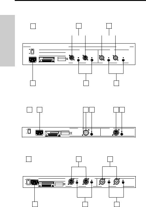
1: Power switch - Use this to turn the power on and off. |
ENGLISH |
|||
2: AC input - Connect the supplied heavy gauge 3-pin “IEC” power cable here. |
||||
|
||||
3: Balanced XLR jack output - Electronically balanced XLR jack output. Wiring is as |
|
|||
follows: pin 2 hot, pin 3 cold, and pin 1 ground.* |
|
|||
4: Balanced 1/4" TRS jack output - Electronically balanced 1/4" TRS jack output. |
|
|||
Wiring is as follows: tip hot, ring cold, and sleeve ground.* |
|
|||
5: Balanced XLR jack input - Electronically balanced XLR jack input. Wiring is as |
|
|||
follows: pin 2 hot, pin 3 cold, and pin 1 ground. |
|
|||
6: Balanced 1/4" TRS jack input - Electronically balanced 1/4" TRS jack input. |
|
|||
Wiring is as follows: tip hot, ring cold, and sleeve ground. |
|
|||
|
|
|
|
|
|
WARNING: The XLR and 1/4" TRS inputs should not be |
|
|
|
|
connected simultaneously, or loading problems may result. |
|
|
|
|
|
|
|
|
* If required, both the XLR and 1/4" TRS jack outputs can be used simultaneously.
7

ENGLISH
System Configurations
IN-LINE |
SAMSON |
|
CONFIGURATION: |
MPL 1640 |
|
|
MAIN MIX OUT L |
MAIN MIX OUT R |
CHANNEL A INPUT |
CHANNEL B INPUT |
|
|
GRAPHIC EQUALIZER E62i 1/3 OCTAVE DUAL 31 BAND CONSTANT Q |
SAMSON |
|
|
∞ |
|
|
∞ |
|
CHANNEL A OUTPUT |
CHANNEL B OUTPUT |
SAMSON |
SERVO - 240 |
INSERT
CONFIGURATION:
|
GRAPHIC EQUALIZER E62i 1/3 OCTAVE DUAL 31 BAND CONSTANT Q |
SAMSON |
|
|
|
∞ |
|
|
|
∞ |
|
CHANNEL A |
CHANNEL A |
CHANNEL B |
CHANNEL B |
INPUT |
OUTPUT |
OUTPUT |
INPUT |
|
MAIN MIX INSERT |
MAIN MIX INSERT |
|
|
L RETURN |
R RETURN |
|
|
SAMSON |
|
|
|
|
MPL 1640 |
|
MAIN MIX INSERT |
MAIN MIX INSERT |
||
|
L SEND |
R SEND |
|
|
MAIN MIX OUT L |
MAIN MIX OUT R |
|
SAMSON |
SERVO - 240 |
8
System Configurations
EFFECTS LOOP
CONFIGURATION:
|
GRAPHIC EQUALIZER E62i 1/3 OCTAVE DUAL 31 BAND CONSTANT Q |
|
SAMSON |
|
|
|
∞ |
|
|
|
∞ |
CHANNEL A |
CHANNEL A |
CHANNEL B |
CHANNEL B |
INPUT |
OUTPUT |
OUTPUT |
INPUT |
|
EFFECTS |
EFFECTS |
|
|
RETURN |
RETURN |
|
|
SAMSON |
|
|
|
|
MPL 1640 |
|
EFFECTS 


 EFFECTS
SEND 


 SEND
SEND
ENGLISH
|
|
|
|
|
MAIN MIX OUT L |
|
MAIN MIX OUT R |
||
|
|
|
|
|
SAMSON |
SERVO - 240 |
USING THE
TWO CHANNELS
OF THE E62i / E30i
INDEPENDENTLY:
|
|
CHANNEL |
CHANNEL A |
B |
|
|
INPUT |
INPUT |
GRAPHIC EQUALIZER E62i 1/3 OCTAVE DUAL 31 BAND CONSTANT Q |
SAMSON |
|
|
∞ |
|
|
∞ |
|
CHANNEL A |
CHANNEL B |
|
OUTPUT |
OUTPUT |
|
CHANNEL |
INSERT |
|
INPUT |
RETURN |
|
SAMSON |
|
|
|
MPL 1640 |
|
|
INSERT |
|
|
SEND |
|
9 |
|
|

ENGLISH
Setting Up and Using
the E62i / E31i / E30i
Setting up your E62i, E31i or E30i Graphic Equalizer is a simple procedure which takes only a few minutes:
1.Remove all packing materials (save them in case of need for future service) and decide where the unit is to be physically placed— it can be used free-standing or mounted in a standard 19" rack (the E62i requires two rack spaces, while the E31i and E30i require only a single rack space).
2.Make sure the power to all mixers and amplifiers in your audio system is off. On the
front panel of the E62i / E31i / E30i, place all ±12 dB, Cut Only and HPF switches to their out (off) position and set the Level slider(s) to their bottom-most “∞ ” setting.
3.Set all Equalizer sliders to their flat (“0”) center detented position.
4.The E62i / E31i / E30i can be used either as an “in-line” device, as an insert device (in conjunction with mixer insert points), or in an effects send-return loop. The illustrations on pages 12 - 13 show each of these typical configurations. Choose the configuration that is best for your application and then begin by making the E62i / E31i / E30i input connections, using either the XLR or 1/4" TRS connectors on the rear panel. WARNING: Both the XLR and 1/4" TRS inputs should not be connected simultaneously, or loading problems may result.
5.Next, make the E62i / E31i / E30i output connections, using the XLR or 1/4" TRS connectors on the rear panel. If required, connections can be made simultaneously to both.
6.Plug in the supplied AC connector and connect it to any standard AC socket. Because of the special relay power-on circuitry built into the E62i / E31i / E30i, you can even plug it into the same power strip that other audio devices (such as a mixing console) are connected to. You can then turn on all devices at once with the single power strip on-off switch, without generating speaker “thumps.”
7.Press the rear panel Power switch in order to turn on the E62i / E31i / E30i. The Bypass
LED(s) will light either red or green, depending upon the setting of the front panel Bypass switch(es). Note that audio signal will be muted for approximately five seconds until the relay power-on circuitry is activated (at which time you’ll hear a click and the audio signal will be unmuted).
8.Apply an input signal to the E62i / E31i / E30i at or about 0 dBm (if sending signal from a mixer output bus, drive the mixer’s output meters at approximately 0 vu). While the input signal is present, slowly raise the front panel Level slider(s) to their center detented “0” points. For best signal-to-noise ratio, the Level slider(s) should be at or near the “0” point during normal operation. However, if the output signal is weak, use the appropriate Level slider(s) to slightly boost the volume (to a maximum of 6 dB). Conversely, if the signal causes the front panel Clip LED(s) to light, use the appropriate Level slider(s) to attenuate volume as necessary. In normal operation, the Clip LED(s) should not light at all; if they do, use the Level sliders to lower the volume of the output signal so that they do not light at all (clipping not only sounds awful, it can also damage speakers!).
10

Setting Up and Using
the E62i /E31i / E30i
9. Experiment by moving each of the Equalizer sliders up and down, carefully listening to |
ENGLISH |
engaged, the blue labels on the front panel indicate settings, with the maximum “+12 dB” |
|
the audible result on the audio signal. Bear in mind that the very lowest and highest |
|
frequency areas may have little or no effect on some signals. If there is significant low |
|
frequency noise (rumble) in the signal, engage the HPF switch(es) as necessary. If you |
|
are using an E62i or E31i, experiment further by pressing in the ±12 dB switch(es) to |
|
deepen the effect of the Equalizer sliders, cutting and boosting by as much as 12 dB |
|
instead of 6 dB. Also try pressing in the Cut Only switch(es) to use the Equalizer sliders |
|
to cut frequencies only without any boost (bear in mind that, when the Cut Only switch is |
|
position for each Equalizer slider representing “flat” and the center detented (“0”) position |
|
of each Equalizer slider representing a cut of -6 or -12 dB, depending upon the setting of |
|
the ±12 dB switch). As you work with the various front panel controls, press the front |
|
panel Bypass switch(es) in and out from time to time in order to compare the effect of the |
|
equalization curve you are creating with the original input signal. |
|
10. Once you’ve created the frequency curve required for your particular application (see |
|
the “About Equalization” section on the following pages for more information), an optional |
|
locking security cover (available from your local Samson dealer) can be placed over the |
|
front panel to make sure that your settings are not inadvertantly altered. |
|
If you have followed all the steps above and are experiencing difficulties with any aspect |
|
of setting up or using your E62i / E31i / E30i, you can call Samson Technical Support |
|
(1-800-372-6766) between 9 AM and 5 PM EST, or contact your local distributor. |
|
11

About Equalization
ENGLISH
The E62i, E31i and E30i give you fine control over shaping a sound, using a process called equalization. But there are few areas of sound engineering more misunderstood than equalization, and, just as good EQ can really help a sound, bad EQ can really hurt it, so read on...
Every naturally occurring sound consists of a broad range of pitches, or frequencies, combined together in a unique way. This blend is what gives every sound its distinctive tonal color. The range of frequencies that can be heard by humans is sometimes called the audible range, and it includes frequencies from as low as 20 Hz (that is, 20 wavecycles per second) to those as high as 20 kHz (that is, 20,000 wavecycles per second).
The E62i and E31i provides a set of high-quality filters that divide the audible range into
31 1/3 octave frequency areas, centered at 20 Hz, 25 Hz, 31.5 Hz, 40 Hz, 50 Hz, 63 Hz, 80 Hz, 100 Hz, 125 Hz, 160 Hz, 200 Hz, 250 Hz, 315 Hz, 400 Hz, 500 Hz, 630 Hz, 800 Hz, 1 kHz, 1.25 kHz, 1.6 kHz, 2 kHz, 2.5 kHz, 3.15 kHz, 4 kHz, 5 kHz, 6.3 kHz, 8 kHz, 10 kHz,
12.5 kHz, 16 kHz, and 20 kHz. The E30i uses the same high-quality filters, instead dividing the audible range into 15 2/3 octave frequency areas, centered at 25 Hz, 40 Hz, 63 Hz,
100 Hz, 160 Hz, 250 Hz, 400 Hz, 630 Hz, 1 kHz, 1.6 kHz, 2.5 kHz, 4 kHz, 6.3 kHz, 10 kHz, and 16 kHz. In all three models, “Constant Q” circuitry ensures that the bandwidth of each of these frequency areas stays the same even when approaching maximum boost or attenuation resulting in greatly reduced phase shifting and intermodulation distortion.
Each frequency area can be cut or boosted by as much as 12 dB. The E62i and E31i models also provide ±12 dB switches; when these switches are off (in the up position), each frequency area is cut or boosted by just 6 dB, giving you finer control and allowing you to construct gentler frequency curves.
In addition, the E62i and E31i models provide a Cut Only mode. If the Cut Only switch(es) on the front panel are off (in their up position), then when an Equalizer slider is in its center detented “0” position, it is having no effect; when it is moved up, the particular frequency area is being boosted; when it is moved down, the frequency area is being attenuated (cut). However, if the Cut Only switch(es) on the front panel are on (in their down position), the blue labels on the front panel indicate the action of moving an Equalizer slider; when it is at its maximum (fully up) position, it is having no effect; when it is moved down, the frequency area is attenuated (cut). In this circumstance, the center detented “0” position represents a cut of -6 dB (if the ±12 dB switch is out) or -12 dB (if the ±12 dB switch is in), and the minimum position represents a cut of -12 dB (if the ±12 dB switch is out) or a whopping -24 dB (if the ±12 dB switch is in).
In most instances, the best way to approach equalization is to think in terms of which frequency areas you need to attenuate, as opposed to which ones you need to boost (boosting a frequency area also has the effect of boosting the overall signal; too much EQ boost can actually cause overload— with the accompanying Peak LED warning!). Be aware of the phenomenon of masking, where loud sounds in one frequency range obscure softer sounds in the same range; by cutting EQ “notches” in a loud signal, you can actually make room for a softer one to shine through. And try not to think of EQ as a miracle worker— no amount of equalization can put a singer in tune or remove the distortion from an overloaded input signal! The key is to get the signal right in the first place, by using correct gain structure and mic placement.
12

About Equalization
If you are using your E62i / E31i / E30i to equalize a complex mono or stereo signal (for example, the master mix output of a mixing console), a more natural sound can be obtained by setting up gentle “smile” curves than by simply cutting or boosting individual frequency areas. For example, if you decide that you want to boost one particular frequency area by 6 dB, try boosting the adjacent areas (the frequency directly above and below the target frequency) by 3 dB each.
If you are using your E62i / E31i / E30i to equalize signal from individual instruments, here are a few general suggestions: Boosting the low frequency areas of instruments such as bass drums or bass guitar will add warmth and make the sound “fatter”; conversely, you may want to attenuate the low frequency components of instruments such as cymbals, high-hats, and shakers so as to “thin” them out. Attenuating mid-range frequencies
(the 1 kHz - 5 kHz area) can give a vocal performance more of an “FM-radio” feel, while boosting those frequencies can help a vocal cut through dense instrumentation. Be careful not to boost high frequencies too much or you risk adding hiss to the signal, though just a touch can help add “shimmer” to an acoustic guitar, ride cymbal, or high-hat. You can also use the highest or lowest equalizer sliders to reduce hiss (by attenuating high frequencies) or rumble (by attenuating low frequencies). Rumble can also be attenuated by engaging the front panel HPF switch(es), which insert a High Pass Filter centered at 80 Hz.
If you are using an E62i or E31i to equalize the signal of an overall mix in a live performance or recording environment, check out the sections in this manual entitled “Using the E62i / E31i With an RTA” and “Using the E62i / E31i to Ring Out A Monitor System” (on pages 24 and 25).
ENGLISH
13
Loading...