


OPERATOR’S MANUAL
MANUEL D’UTILISATION MANUAL DEL OPERADOR


 C430
C430 


 RY34421
30CC 4-CYCLE |
|
|
STRING TRIMMERS |
|
|
TAILLE-BORDURES |
|
|
À LIGNE 4 TEMPS DE 30 CC |
S430 |
|
RECORTADORAS DE HILO |
||
RY34441 |
||
DE CUATRO TIMPOS 30 CC |
|
CS — RY34421
SS — RY34441
ALL VERSIONS
TOUTES LES VERSIONS
TODAS LAS VERSIONES
Your trimmer has been engineered and manufactured to our high standard for dependability, ease of operation, and operator safety. When properly cared for, it will give you years of rugged, trouble-free performance.
 WARNING: To reduce the risk of injury, the user must read and understand the operator’s manual before using this product.
Thank you for your purchase.
SAVE THIS MANUAL FOR FUTURE REFERENCE
Le taille-bordures à ligne a été conçue et fabriquée conformément à nos strictes normes de fiabilité, simplicité d’emploi et sécurité d’utilisation. Correctement entretenue, elle vous donnera des années de fonctionnement robuste et sans problème.
 AVERTISSEMENT : Pour réduire les risques de blessures, l’utilisateur doit lire et veiller à bien comprendre le manuel d’utilisation avant d’employer ce produit.
Merci de votre achat.
Su recortadoras de hilo ha sido diseñada y fabricada de conformidad con las estrictas normas para brindar fiabilidad, facilidad de uso y seguridad para el operador. Con el debido cuidado, le brindará muchos años de sólido y eficiente funcionamiento.
 ADVERTENCIA: Para reducir el riesgo de lesiones, el usuario debe leer y comprender el manual del operador antes de usar este producto.
Le agradecemos su compra.
CONSERVER CE MANUEL POUR |
GUARDE ESTE MANUAL PARA |
FUTURE RÉFÉRENCE |
FUTURAS CONSULTAS |
See this fold-out section for all of the figures referenced in the operator’s manual. Consulter l’encart à volets afin d’examiner toutes les figures mentionnées dans le manuel d’utilisation.
Consulte esta sección desplegable para ver todas las figuras a las que se hace referencia en el manual del operador.
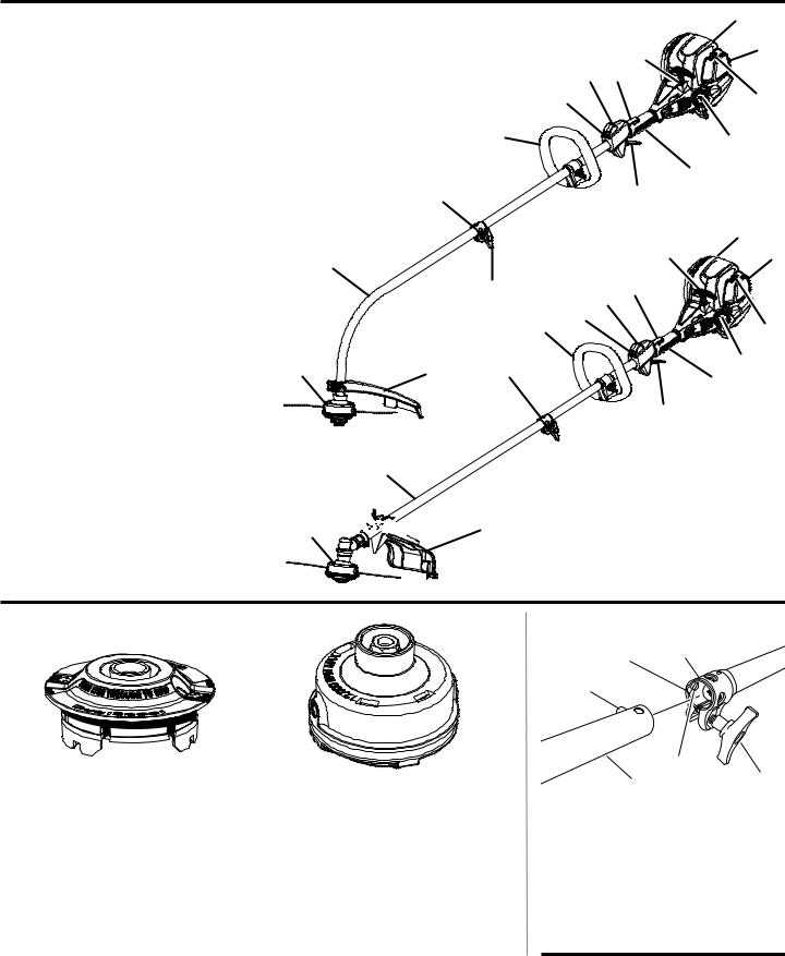
Fig. 1
A - Reel Easy string head (tête à ligne de coupe de Reel Easy, cabezal del hilo de Reel Easy)
B - Drive shaft housing (tube de l’arbre moteur, alojamiento del eje de impulsión)
C - Coupler (coupleur, acoplador)
D - Front handle (poignée avant, mango delantero)
E - Strap hanger (dispositif d’accrochage, colgador para la correa)
F - Stop switch (commutateur d’arrêt, interruptor de apagado)
G - Trigger lock-out (gâchette avec verrou, gatillo con seguro)
H - Starter grip and rope (poignée et cordon du lanceur, mango y cuerda del arrancador)
I- Primer bulb (poire d’amorçage, bomba de cebado)
J- Choke lever (levier de volet de départ, palanca del anegador)
K- Fuel cap (bouchon de carburant, tapa del tanque)
L- Rear handle (poignée arrière, mango trasero)
M- Throttletrigger(gâchetted’accélérateur, gatillo del acelerador)
N - Knob (bouton, perilla)
O - Curved shaft grass deflector (déflecteur d’herbe d’arbre courbe, deflector de pasto del eje curvo)
P- Straightshaftgrassdeflector(déflecteur d’herbe d’arbre droit, deflector de pasto para eje recto)
Q- Muffler (silencieux, silenciador)
C430 |
|
|
|
|
|
Q |
|
|
|
|
|
|
|
|
|
|
|
|
H |
I |
|
|
|
|
|
|
|
|
|
|
F |
|
G |
|
|
|
|
E |
|
|
J |
|
|
|
|
|
|
|
|
|
D |
|
|
|
K |
|
|
|
|
|
|
|
|
|
|
|
|
|
L |
|
C |
|
|
|
M |
|
|
|
|
|
|
H |
Q |
|
B |
|
|
|
I |
|
|
|
|
|
|
|
|
|
|
N |
|
F |
G |
|
|
|
|
E |
|
|
|
|
|
D |
|
|
J |
|
|
|
|
|
|
||
A |
O |
C |
|
|
|
K |
|
|
|
L |
|||
|
|
|
|
|
|
|
|
|
|
|
|
M |
|
B  N
N
S430
A 


 P
P
Fig. 2
DUAL SPOOL™ FIXED LINE STRING HEAD |
|
INSERT |
REEL-EASY™ TAP ADVANCE SYSTEM |
BOBINE À FIL FIXE DUAL SPOOLTM |
AVANCE DE LA LIGNE DE COUPE À TAPANT |
INSERTO PARA CABEZAL DEL HILO CON |
REEL-EASY™ |
LÍNEA FIJA DUAL SPOOL™ |
SISTEMA DE AVANCE DE HILO POR GOLPE |
|
REEL-EASY™ |
|
|
Fig. 3
D B C 
A
F
G E
A - Button (bouton, botón)
B - Guide recess (logement guide, hueco guía) C - Coupler (coupleur, acoplador)
D - Power head shaft (arbre du bloc moteur, eje del cabezal motor)
E - Knob (bouton, perilla)
F - Positioning hole (trou de positionnement, orificio de posicionamiento)
G - Trimmer attachment (accessoire taillebordures, aditamento para recortar)
ii
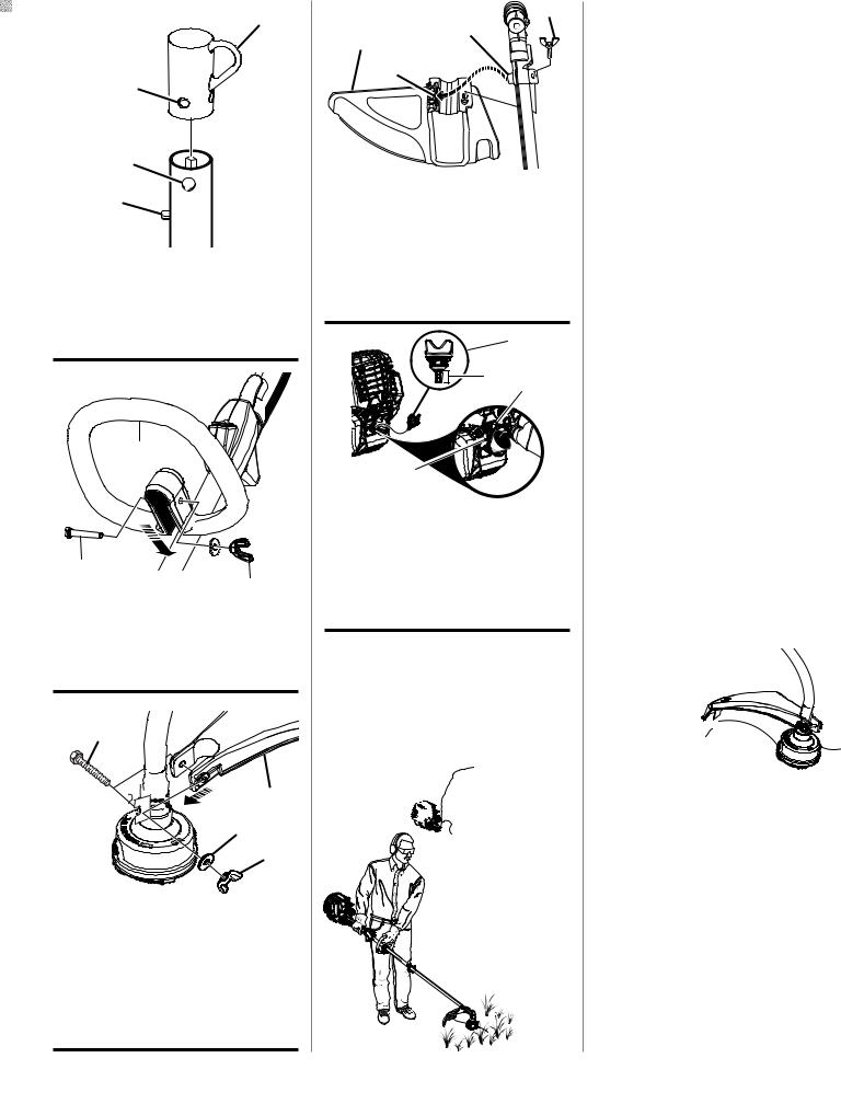
Fig. 4 |
A |
|
B
C
D
A - Hanger cap (capuchon de suspension, tapa de suspensión)
B - Hole (trou, orificio)
C - Secondary hole (trou secondaire, orificio secundario)
D - Button (bouton, botón)
Fig. 5
A
B 
 C D
C D
A - Front handle (poignée avant, mango delantero)
B - Bolt (boulon, perno)
C - Washer (rondelle, arandela)
D - Wing nut (écrou papillon, tuerca de mariposa)
Fig. 6 F
E
D
C 


B
A
A - Wing nut (écrou papillon, tuerca de mariposa)
B - Flat washer (rondelle plate, arandela plana) C - Bracket (support, soporte)
D - Grass deflector (déflecteur d’herbe, deflector de pasto)
E - Hex screw (vis à six pans, tornillo de hexagonal)
F - Curved shaft (d’arbre courbe, pasto del eje curvo)
Fig. 7 |
D |
A |
C |
|
|
|
B |
A - Straight shaft grass deflector (déflecteur d’herbe d’arbre droit, deflector de pasto para eje recto)
B - Slot (fente, ranura)
C - Tab (languette, orejeta)
D - Wing screw (vis à oreilles, tornillo de mariposa)
Fig. 8 |
A |
B C
D
A - Oil cap/dipstick (bouchon/jauge d’huile, tapa de relleno de aceite / varilla medidora de aceite)
B - Hatched area (zone hachurée, área cubierta con rayas entrecruzadas)
C - Funnel (entonnoir, embudo)
D - Oil fill hole (orifice de remplissage d’huile, agujero de llenado de aceite)
Fig. 9
PROPER OPERATING POSITION
BONNE POSITION DE TRAVAIL
POSICIÓN CORRECTA PARA EL MANEJO DE
LA HERRAMIENTA
Fig. 10 |
A |
B
C
D
A - Curved shaft trimmer (taille-bordures à arbre courbe, recortadora de eje curvo)
B - Dangerous cutting area (zone de coupe dangereuse, área peligrosa de corte)
C - Direction of rotation (sens de rotation, sentido de rotación)
D - Best cutting area (zone d’efficacité maximum, mejor área de corte)
Fig. 11 |
A |
B
C D
A - Straight shaft trimmer (taille-bordures à arbre droit, recortadora de eje recto)
B - Dangerous cutting area (zone de coupe dangereuse, área peligrosa de corte)
C - Direction of rotation (sens de rotation, sentido de rotación)
D - Best cutting area (zone d’efficacité maximum, mejor área de corte)
Fig. 12
B
A
A - Straight shaft trimmer line trimming cutoff blade (lame de sectionnement de ligne du taille-bordures à arbre droit, cuchilla de corte de hilo de la recortadora de eje recto)
B - Curved shaft trimmer line trimming cut-off blade (lame de sectionnement de ligne du taille-bordures à arbre courbe, cuchilla de corte de hilo de la recortadora de eje curvo)
iii

Fig. 13 A
 B
B
C 

A - Stop switch (commutateur d’arrêt, interruptor de apagado)
B - Trigger lock-out (gâchette avec verrou, gatillo con seguro)
C - Throttle trigger (gâchette d’accélérateur, gatillo del acelerador)
Fig. 14 |
C |
A |
B |
 D
D
A - Stop switch (commutateur d’arrêt, interruptor de apagado)
B - Trigger lock-out (gâchette avec verrou, gatillo con seguro)
C - Primer bulb (poire d’amorçage, bomba de cebado)
D - Throttle trigger (gâchette d’accélérateur, gatillo del acelerador)
Fig. 15
A |
RUN |
B |
|
HALF |
|
|
|
|
|
CHOKE |
|
|
FULL |
|
|
CHOKE |
|
RUN |
B |
|
HALF
CHOKE
C CHOKEFULL
A - Run position (position de marche , posición de marcha)
B - Start lever (palanca de arranque, levier de voletRUNde départ)
C - StartHALFposition (position de démarrage,
posiciónCHOKE de arranque)
FULL
CHOKE
Fig. 16
A
A - Spool retainer (retenue de bobine, retén del carrete)
Fig. 17 A
B
A - Spool retainer (retenue de
 bobine, retén
 del carrete)
B - Spool (bobine, carrete)
Fig. 18 |
A |
B |
A - Eyelet (oeillet, ojillo)
B - Arrow on spool (flèche sur la bobine, flecha en el carrete)
Fig. 19
A
A - Pull strings (tirer vers l’extérieur, tira del hilo)
B - Rotate the spool counterclock wise (tourner le bobine dans le sens antihoraire, gire a la izquierda el carrete)
iv
Fig. 20
A
A - Pull strings (tirer vers l’extérieur, tira del hilo)
Fig. 21
A
B
C
A - String head housing (boîtier de tête de coupe, alojamiento del cabezal de hilo)
B - Spool (bobine, carrete)
C - Spool retainer (retenue de bobine, retén del carrete)
Fig. 22
A
C
B
A - Insert line through slots until approx.
1 in. protrudes from holes |
[insérer les |
fils dans les fentes de manière à les faire |
|
dépasser d’environ 25 mm (1 po), introduzca |
|
los hilos a través de las ranuras hasta que |
|
sobresalgan aproximadamente |
25 mm (1 |
pulg.) de los orificios] |
|
B - Eyelet (trou, ojillos)
C - Pull line from holes to remove (tirer les fils hors des trous afin de les retirer, tire de los hilospara retirar los a través de los orificios)
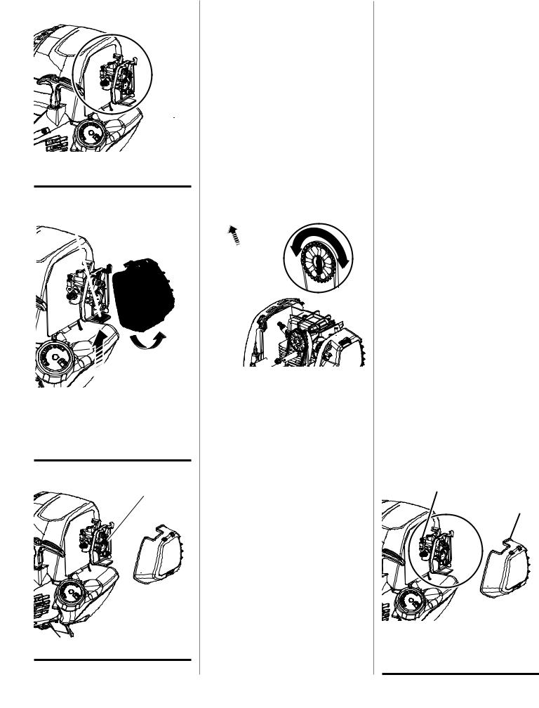
Fig. 23
A
A - Idle speed screw (vis de ralenti, tornillo de ajuste de la velocidad en vacío)
Fig. 24
A
C
B
A - Latch (loquet, pestillo)
B - Air filter cover (couvercle du filtre à air, tapa del filtro de aire)
C - Pull and lift cover to open (tirer sur le couvercle pour l’ouvrir, tire de la tapa para abrirla)
Fig. 25
A
A - Filter screen (filtre écran, filtro pantalla)
Fig. 26
B
A
C
A - Screw (vis, tornillo) |
A |
|
B - Top engine cover (couvercle moteur supérieur, cubierta superior del motor)
C - Bottom cover (couvercle inférieure, cubierta inferior)
Fig. 27
A
A
B
A - Starter grip and rope (poignée et cordon du lanceur, mango y cuerda del arrancador)
B - Deep hole in camshaft gear (Trou profond situé dans l’engrenage de l’arbre à cames Orificio profundo en el engranaje del árbol de levas)
Fig. 28 |
C |
D |
|
||
B |
|
|
A
A - Feeler gauge (jauge d’épaisseur, calibrador de separaciones)
B - Rocker arm (culbuteur, balancín)
C - Rocker arm cover (cache-culasse, tapa del balancín)
D - Screw (vis, tornillo)
Fig. 29 |
C |
|
A |
B
A - Retaining nut (écrou de retenue, tuerca de retencion)
B - Adjusting nut (écrou de réglage, tuerca de ajuste)
C - Stud (goujon, elemento estructural)
Fig. 30
A
B
A - Idle speed screw (vis de ralenti, tornillo de ajuste de la velocidad en vacío)
B - Air filter cover (couvercle du filtre à air, tapa del filtro de aire)
v

TABLE OF CONTENTS
TABLE DES MATIÈRES / ÍNDICE DE CONTENIDO
Introduction....................................................................................................................................................................... |
2 |
Introduction / Introducción |
|
General Safety Rules......................................................................................................................................................... |
3 |
Règles de sécurité générales / Reglas de seguridad generales |
|
Specific Safety Rules........................................................................................................................................................ |
4 |
Règles de sécurité particulières / Reglas de seguridad específicas |
|
Symbols............................................................................................................................................................................ |
5 |
Symboles / Símbolos |
|
Features............................................................................................................................................................................ |
6 |
Caractéristiques / Características |
|
Assembly........................................................................................................................................................................ |
7-8 |
Assemblage / Armado |
|
Operation..................................................................................................................................................................... |
8-10 |
Utilisation / Funcionamiento |
|
Maintenance............................................................................................................................................................... |
11-13 |
Entretien / Mantenimiento |
|
Troubleshooting.......................................................................................................................................................... |
14-15 |
Dépannage / Solución de problemas |
|
Warranty..................................................................................................................................................................... |
15-17 |
Garantie / Garantía |
|
Parts Ordering and Service................................................................................................................................ |
Back Page |
Commande de pièces et réparation / Pedidos de piezas y servicio.......................................................... |
Page arrière / Pág. posterior |
INTRODUCTION
INTRODUCTION / INTRODUCCIÓN
This product has many features for making its use more pleasant and enjoyable. Safety, performance, and dependability have been given top priority in the design of this product making it easy to maintain and operate.
* * *
Ce produit offre de nombreuses fonctions destinées à rendre son utilisation plus plaisante et satisfaisante. Lors de la conception de ce produit, l’accent a été mis sur la sécurité, les performances et la fiabilité, afin d’en faire un outil facile à utiliser et à entretenir.
* * *
Este producto ofrece numerosas características para hacer más agradable y placentero su uso. En el diseño de este producto se ha conferido prioridad a la seguridad, el desempeño y la fiabilidad, por lo cual se facilita su manejo y mantenimiento.
2

GENERAL SAFETY RULES
WARNING:
Read and understand all instructions. Failure to follow all instructions listed below may result in electric shock, fire and/or serious personal injury.
READ ALL INSTRUCTIONS
For safe operation, read and understand all instructions before using this product. Follow all safety instructions. Failure to follow all safety instructions listed below, can result in serious personal injury.
Do not allow children or untrained individuals to use this unit.
Never start or run the engine in a closed or poorly ventilated area; breathing exhaust fumes can kill.
Clear the work area before each use. Remove all objects such as rocks, broken glass, nails, wire, or loose string which can be thrown or become entangled in the cutting line or blade.
Always wear eye protection with side shields marked to comply with ANSI Z87.1 along with hearing protection when operating this equipment.
Wear heavy, long pants, long sleeves, boots, and gloves. Do not wear loose fitting clothing, short pants, sandals, or go barefoot. Do not wear jewelry of any kind.
Heavy protective clothing may increase operator fatigue, which could lead to heat stroke. During weather that is hot and humid, heavy work should be scheduled for early morning or late afternoon hours when temperatures are cooler.
Product users on United States Forest Service land, and in some states, must comply with fire prevention regulations. This product is equipped with a spark arrestor; however, other user requirements may apply. Check with your federal, state, or local authorities.
Never operate this unit on the operator’s left side.
Secure long hair above shoulder level to prevent entanglement in moving parts.
Keep all bystanders, children, and pets at least 50 ft. away. Bystanders should be encouraged to wear eye protection. If you are approached, stop the engine and cutting attachment. In the case of bladed units, there is the added risk of injury to bystanders from being struck with the moving blade in the event of a blade thrust or other unexpected reaction of the saw.
Do not operate this unit when you are tired, ill, or under the influence of alcohol, drugs, or medication.
Do not operate in poor lighting.
Keep firm footing and balance. Do not overreach. Overreaching can result in loss of balance or exposure to hot surfaces.
Keep all parts of your body away from any moving part.
To avoid hot surfaces, never operate the unit with the bottom of the engine above waist level.
Do not touch area around the muffler or cylinder of the unit, these parts get hot from operation. Contact with hot surfaces could result in possible serious personal injury.
Always stop the engine and remove the spark plug wire before making any adjustments or repairs except for carburetor adjustments.
Inspect the unit before each use for loose fasteners, fuel leaks, etc. Replace any damaged parts before use.
The cutting attachment should never rotate at idle during normal use. The cutting attachment may rotate at idle during carburetor adjustments.
It has been reported that vibrations from hand-held tools may contribute to a condition called Raynaud’s Syndrome in certain individuals. Symptoms may include tingling, numbness, and blanching of the fingers, usually apparent upon exposure to cold. Hereditary factors, exposure to cold and dampness, diet, smoking, and work practices are all thought to contribute to the development of these symptoms. It is presently unknown what, if any, vibrations or extent of exposure may contribute to the condition. There are measures that can be taken by the operator to possibly reduce the effects of vibration:
a)Keep your body warm in cold weather. When operating the unit wear gloves to keep hands and wrists warm. It is reported that cold weather is a major factor contributing to Raynaud’s Syndrome.
b)After each period of operation, exercise to increase blood circulation.
c)Take frequent work breaks. Limit the amount of exposure per day.
d)Keep the tool well maintained, fasteners tightened, and worn parts replaced.
If you experience any of the symptoms of this condition, immediately discontinue use and see your physician about these symptoms.
Mix and store fuel in a container approved for gasoline.
Mix fuel outdoors where there are no sparks or flames. Wipe up any fuel spillage. Move 30 ft. away from refueling site before starting engine. Slowly remove the fuel cap after stopping engine. Do not smoke when refueling.
Stop the engine and allow to cool before refueling or storing the unit.
Allow the engine to cool; empty the fuel tank and secure the unit from moving before transporting in a vehicle.
Wear your protective equipment and observe all safety instructions. For units equipped with a clutch, be sure the cutting attachment stops turning when the engine idles. When the unit is turned off make sure the cutting attachment has stopped before the unit is set down.
3 — English

SPECIFIC SAFETY RULES
SPECIFIC SAFETY RULES FOR TRIMMER USE
Inspect before use. Replace damaged parts. Make sure fasteners are in place and secure. Check for fuel leaks.
Replace string head if cracked, chipped, or damaged in any way. Be sure the string head or blade is properly installed and securely fastened. Failure to do so can cause serious injury.
Make sure all guards, straps, deflectors, and handles are properly and securely attached.
Never use blades, flailing devices, wire, or rope. Use only the manufacturer’s replacement line in the cutting head. Do not use any other cutting attachment. To install any other brand of cutting head to this string trimmer can result in serious personal injury.
Never operate unit without the grass deflector in place and in good condition.
Maintain a firm grip on both handles while trimming. Keep string head below waist level. Never cut with the string head located over 30 in. or more above the ground.
4 — English

SYMBOLS
The following signal words and meanings are intended to explain the levels of risk associated with this product.
SYMBOL |
SIGNAL |
MEANING |
|
|
|
|
DANGER: |
Indicates an imminently hazardous situation, which, if not avoided, will result |
|
in death or serious injury. |
|
|
|
|
|
|
|
|
WARNING: |
Indicates a potentially hazardous situation, which, if not avoided, could result |
|
in death or serious injury. |
|
|
|
|
|
|
|
|
CAUTION: |
Indicates a potentially hazardous situation, which, if not avoided, may result in |
|
minor or moderate injury. |
|
|
|
|
|
|
|
|
CAUTION: |
(Without Safety Alert Symbol) Indicates a situation that may result in property |
|
damage. |
|
|
|
Some of the following symbols may be used on this product. Please study them and learn their meaning for safe operation of this product.
SYMBOL |
NAME |
EXPLANATION |
|
Safety Alert |
Indicates a potential personal injury hazard. |
|
|
|
|
Read Operator’s Manual |
To reduce the risk of injury, user must read and under- |
|
stand operator’s manual before using this product. |
|
|
|
|
|
Always wear eye protection with side shields marked to |
|
Eye and Hearing Protection |
comply with ANSI Z87.1 along with hearing protection |
|
|
when operating this equipment. |
|
|
|
|
Keep Bystanders Away |
Keep all bystanders at least 50 ft. away. |
|
|
|
|
Ricochet |
Thrown objects can ricochet and result in personal injury |
|
or property damage. |
|
|
|
|
|
|
|
|
No Blade |
Do not install or use any type of blade on a product dis- |
|
playing this symbol. |
|
|
|
|
|
|
|
5 — English
|
FEATURES |
|
|
PRODUCT SPECIFICATIONS |
|
Weight - (without fuel) |
|
C430................................................................................................................................................................... |
10.7 lbs. |
S430................................................................................................................................................................... |
11.8 lbs. |
Line cutting width |
|
C430........................................................................................................................................................................ |
17 in. |
S430........................................................................................................................................................................ |
18 in. |
Engine displacement ................................................................................................................................................. |
30cc |
Engine Lubricant Volume............................................................................................................................................ |
65 ml |
Line diameter |
|
Reel Easy String Head......................................................................................................................................... |
.095 in. |
Dual Spool String Head............................................................................................................. |
.095 in. to .105 in. max. |
KNOW YOUR STRING TRIMMER
See Figure 1.
The safe use of this product requires an understanding of the information on the tool and in this operator’s manual as well as a knowledge of the project you are attempting. Before use of this product, familiarize yourself with all operating features and safety rules.
GRASS DEFLECTOR
The trimmer includes a grass deflector that helps protect you from flying debris.
OIL CAP/DIPSTICK
Remove the oil fill cap to check and add lubricant when necessary.
ERGONOMIC DESIGN
The design of the trimmer provides for easy handling. It is designed for comfort and ease of grasp when operating in different positions and at different angles.
TOP-MOUNTED ENGINE
The top-mounted engine improves balance and is located away from the dust and debris of the cutting area.
6 — English
ASSEMBLY
UNPACKING
This product requires assembly.
nCarefully remove the product and any accessories from the box. Make sure that all items listed in the packing list are included.
 WARNING:
To prevent accidental starting that could cause serious personal injury, always disconnect the engine spark plug wire from the spark plug when assembling parts.
 WARNING:
Do not use this product if any parts on the packing list are already assembled to your product when you unpack it. Parts on this list are not assembled to the product by the manufacturer and require customer installation. Use of a product that may have been improperly assembled could result in serious personal injury.
nInspect the product carefully to make sure no breakage or damage occurred during shipping.
nDo not discard the packing material until you have carefully inspected and satisfactorily operated the product.
nIf any parts are damaged or missing, please call 1-800-860-4050 for assistance.
PACKING LIST
C430
Trimmer Assembly
Dual Spool™ Fixed Line Adaptor
Front Handle
Curved Shaft Grass Deflector
Bottle of 4-Cycle Lubricant
Paper Funnel
Hanger Cap
Operator’s Manual
S430
Trimmer Assembly
Dual Spool™ Fixed Line Adaptor
Front Handle
Straight Shaft Grass Deflector
Bottle of 4-Cycle Lubricant
Paper Funnel
Hanger Cap
Operator’s Manual
 WARNING:
If any parts are damaged or missing do not operate this product until the parts are replaced. Use of this product with damaged or missing parts could result in serious personal injury.
INSTALLING THE POWER HEAD TO THE ATTACHMENT
See Figures 2 - 3.
 WARNING:
Never install, remove, or adjust any attachment while power head is running. Failure to stop the engine can cause serious personal injury.
The attachment connects to the power head by means of a coupler device.
Stop the engine and disconnect the spark plug wire.
Loosen the knob on the coupler of the power head shaft and remove the end cap from the attachment.
Push in the button located on the attachment shaft. Align thebuttonwith the guiderecessonthepowerheadcoupler and slide the two shafts together. Rotate the attachment shaft until the button locks into the positioning hole.
NOTE: If the button does not release completely in the positioning hole, the shafts are not locked into place. Slightly rotate from side to side until the button is locked into place.
Tighten the knob securely.
WARNING:
Be certain the knob is fully tightened before operating equipment; check it periodically for tightness during use to avoid serious personal injury.
REMOVING THE ATTACHMENT FROM THE POWER HEAD
For removing or changing the attachment:
Stop the engine and disconnect the spark plug wire.
Loosen the knob.
Push in the button and twist the shafts to remove and separate ends.
 WARNING:
Do not attempt to modify this product or create accessories not recommended for use with this product. Any such alteration or modification is misuse and could result in a hazardous condition leading to possible serious personal injury.
ATTACHING THE STORAGE HANGER
See Figure 4.
There are two ways to hang your attachment for storage.
To use the hanger cap, push in the button and place the hanger cap over end of the lower end attachment shaft. Slightly rotate the cap from side to side until the button locks into place.
7 — English

ASSEMBLY
The secondary hole in the attachment shaft can be used for hanging purposes as well.
ATTACHING THE FRONT HANDLE
See Figure 5.
Remove wing nut, washer, and bolt from the front handle.
Install the front handle onto the top side of the drive shaft housing in the area indicated by the label.
NOTE: The open side of the handle should face the operator.
Place the bolt through the front handle.
NOTE: The hex bolt head fits inside the hex recess molded into one side of the handle.
Reinstall the washer and wing nut.
Tighten wing nut securely.
ATTACHING THE GRASS DEFLECTOR
WARNING:
The line cut-off blade on the grass deflector is sharp. Avoid contact with the blade. Failure to avoid contact can result in serious personal injury.
TO ATTACH THE CURVED SHAFT GRASS DEFLECTOR — C430
See Figure 6.
Remove hex screw, flat washer, and wing nut from grass deflector.
Press the grass deflector onto the bottom of the curved shaft as shown.
Insert the hex screw through the grass deflector and the bracket on the curved shaft.
Place the flat washer on the hex screw.
Place the wing nut on the hex screw and tighten securely.
TO ATTACH THE STRAIGHT SHAFT GRASS DEFLECTOR — S430
See Figure 7.
Remove the wing screw from the grass deflector.
Insert the tab on the mounting bracket in the slot on the grass deflector.
Align the screw hole in the mounting bracket with the screw hole in the grass deflector.
Insert the wing screw through the mounting bracket and into the grass deflector.
Tighten the screw securely.
OPERATION
WARNING:
Do not allow familiarity with this product to make you careless. Remember that a careless fraction of a second is sufficient to inflict serious injury.
WARNING:
Always wear eye protection with side shields marked to comply with ANSI Z87.1, along with hearing protection. Failure to do so could result in objects being thrown into your eyes and other possible serious injuries.
WARNING:
Never use blades, flailing devices, wire, or rope on this product. Do not use any attachments or accessories not recommended by the manufacturer of this product. The use of attachments or accessories not recommended can result in serious personal injury.
WARNING:
Gasoline and its vapors are highly flammable and explosive. To prevent serious personal injury and property damage, handle it with care. Keep away from ignition sources and open flames, handle outdoors only, do not smoke and wipe up spills immediately.
FUELING AND REFUELING THE TRIMMER
Clean surface around fuel cap to prevent contamination.
Loosen fuel cap slowly by turning counterclockwise. Rest the cap on a clean surface.
Carefully pour fuel into the tank. Avoid spillage.
Prior to replacing the fuel cap, clean and inspect the gasket.
Immediately replace fuel cap and hand tighten by turning it clockwise. Wipe up any fuel spillage.
NOTE: It is normal for smoke to be emitted from a new engine after first use.
8 — English

OPERATION
WARNING:
Always shut off engine before fueling. Never add fuel to a machine with a running or hot engine. Move at least 30 ft. from refueling site before starting engine. Do not smoke and stay away from open flames and sparks. Failure to safely handle fuel could result in serious personal injury.
OXYGENATED FUELS
DO NOT USE E85 FUEL. IT WILL VOID YOUR WARRANTY.
NOTE: Fuel system damage or performance problems resulting from the use of an oxygenated fuel containing more than the percentages of oxygenates stated below are not covered under warranty.
Ethanol. Gasoline containing up to 10% ethanol by volume (commonly referred to as E10) or 15% ethanol by volume (commonly referred to as E15) are acceptable. E85 is not.
CAUTION:
Attempting to start the engine before it has been properly filled with lubricant will result in equipment failure.
CAUTION:
Do not overfill. Overfilling the crankcase may cause excessive smoke, oil loss, and engine damage.
OPERATING THE TRIMMER
See Figure 9.
WARNING:
Engine housing may become hot during trimmer operation. Do not rest or place your arm, hand, or any body part against the engine housing during trimmer operation. Only hold the trimmer as shown in Figure 9 with all body parts clear of engine housing. Extended contact with the engine housing may result in burns or other injuries.
WARNING:
Always position the unit on the operator’s right side. The use of the unit on the operator’s left side will expose the user to hot surfaces and can result in possible burn injury.
ADDING/CHECKING ENGINE LUBRICANT
See Figure 8.
Engine lubricant has a major influence on engine performance and service life. This unit is shipped with a 20W50 engine lubricant to assist in the break-in period. For best operating performance, continuing to use 20W50 engine lubricant is recommended, however, SAE 30, 10W30, or 10W40 are all acceptable lubricants to use in this product. Always use a 4-stroke engine lubricant that meets or exceeds the requirements for API service classification SJ. Check lubricant level before each use.
NOTE: Non-detergent or 2-stroke engine lubricants will damage the engine and should not be used.
To add engine lubricant:
WARNING:
To avoid burns from hot surfaces, never operate unit with the bottom of the engine above waist level.
Hold the trimmer with your right hand on the rear handle and your left hand on the front handle. Keep a firm grip with both hands while in operation. Trimmer should be held at a comfortable position with the rear handle about hip height.
Cut tall grass from the top down. This will prevent grass from wrapping around the shaft housing and string head which could cause damage from overheating. If grass becomes wrapped around the string head, STOP THE ENGINE, disconnect the spark plug wire, and remove the grass.
Remove the cap and seal from lubricant bottle pro- |
WARNING: |
|
vided. |
||
Always hold the string trimmer away from the body keep- |
||
Unscrew the oil cap/dipstick and remove. |
||
ing clearance between the body and the product. Any |
||
Using funnel provided, add entire bottle of engine lubricant |
||
contact with the housing or string trimmer cutting head can |
||
through oil fill hole. |
||
result in burns and/or other serious personal injury. |
||
Reinstall the oil cap/dipstick and secure. |
||
|
||
To check engine lubricant level: |
|
|
Set unit on a flat surface. |
|
|
Wipe dipstick clean and re-seat in hole; do not rethread. |
|
|
Removedipstickagainandchecklubricantlevel.Lubricant |
|
|
level should fall within the hatched area on the dipstick. |
|
|
If level is low, add engine lubricant until the fluid level rises |
|
|
to the upper portion of the hatched area on the dipstick. |
|
|
Replace and secure the oil cap/dipstick. |
|
|
9 — English |
||

OPERATION
TO ADVANCE THE CUTTING LINE (REEL EASY STRING HEAD)
Line advance is controlled by tapping the string head on grass while running engine at full throttle.
Run engine at full throttle.
Tap the knob on ground to advance line. The line advances each time the knob is tapped. Do not hold the knob on the ground.
NOTE: The line trimming cut-off blade on the grass deflector will cut the line to the correct length.
NOTE: If the line is worn too short you may not be able to advance the line by tapping it on the ground. If so, stop the engine and manually advance the line.
To advance the cutting line manually:
Stop the engine and disconnect the spark plug wire.
Push the knob in while pulling on line(s) to manually advance the line.
NOTE: Dual Spool™ Fixed Line Adaptor line cannot be advanced. To replace the line, refer to Installing Line in Dual Spool™ Fixed Line Adaptor later in this manual.
CUTTING TIPS
See Figures 10 -11.
Avoid hot surfaces by always keeping the tool away from your body. (Proper operating position shown in figure 9.)
Keep the trimmer tilted toward the area being cut; this is the best cutting area.
The curved shaft trimmer cuts when passing the unit from right to left. The straight shaft trimmer cuts when passing the unit from left to right. This will avoid throwing debris at the operator. Avoid cutting in the dangerous area shown in illustration.
Use the tip of line to do the cutting; do not force string head into uncut grass.
Wire and picket fences cause extra line wear, even breakage. Stone and brick walls, curbs, and wood may wear line rapidly.
Avoid trees and shrubs. Tree bark, wood moldings, siding, and fence posts can easily be damaged by the line.
GRASS DEFLECTOR LINE TRIMMING CUT-OFF BLADE
See Figure 12.
The trimmer is equipped with a line trimming cut-off blade on the grass deflector. For best cutting, advance line until it is trimmed to length by the cut-off blade. Advance the line whenever you hear the engine running faster than normal, or when trimming efficiency diminishes. This will maintain best performance and keep the line long enough to advance properly.
STARTING AND STOPPING
See Figures 13 - 15.
Trimmer should be on a flat, bare surface for starting.
To start a cold engine:
Slowly press the primer bulb 10 times.
NOTE: After the 7th press, fuel should be visible in the primer bulb. If it is not, continue to press the primer until you see fuel in the bulb.
Set the choke lever to FULL CHOKE position.
With the throttle trigger at idle, pull the starter handle sharply until the engine attempts to run. Do not pull the starter handle more than 4 times.
Set the choke lever to HALF CHOKE position.
Pull the starter grip until the engine runs. Do not pull the starter grip more than 6 times.
NOTE: If the engine does not start, return to full choke position and repeat the steps that follow.
Allow the engine to run for 10 seconds, then set the choke lever to the RUN position.
To restart a warm engine:
Slowly press the primer bulb 10 times.
Set the choke lever to the RUN position.
Pull the starter grip until the engine runs. DO NOT SQUEEZE the throttle trigger to start a warm engine.
To stop the engine:
To stop the engine, depress the STOP switch to the stop position “  ”.
”.
IF ASSISTANCE IS REQUIRED FOR THIS PRODUCT:
Do not return this product to the retail store where it was purchased. Please call our Customer Service Department for any issues you may have.
For Help Call: 1-800-860-4050
10 — English

MAINTENANCE
WARNING:
When servicing, use only identical replacement parts. Use of any other parts may create a hazard or cause product damage.
WARNING:
Always wear eye protection with side shields marked to comply with ANSI Z87.1, along with hearing protection. Failure to do so could result in objects being thrown into your eyes and other possible serious injuries.
WARNING:
Before inspecting, cleaning, or servicing the machine, shut off engine, wait for all moving parts to stop, and disconnect spark plug wire and move it away from spark plug. Failure to follow these instructions can result in serious personal injury or property damage.
GENERAL MAINTENANCE
Avoid using solvents when cleaning plastic parts. Most plastics are susceptible to damage from various types of commercial solvents and may be damaged by their use. Use clean cloths to remove dirt, dust, lubricant, grease, etc.
WARNING:
Do not at any time let brake fluids, gasoline, petroleumbased products, penetrating lubricants, etc., come in contact with plastic parts. Chemicals can damage, weaken or destroy plastic which may result in serious personal injury.
You can often make adjustments and repairs described here. For other repairs, have the trimmer serviced by an authorized service dealer.
SPOOL REPLACEMENT REEL-EASY™ TAP ADVANCE SYSTEM
See Figures 16 - 18.
If replacing line only, refer to Line Replacement later in this manual.
Use only .095 in. trimmer line.
Stop the engine and disconnect the spark plug wire. Hold the string head and unscrew the spool retainer.
To remove the spool retainer:
Turn the spool retainer counterclockwise for 26CS. Turn the spool retainer clockwise for 26SS.
Remove the empty spool from the string head.
NOTE: It is not necessary to remove the string head housing from the drive shaft.
Insert the new spool into the string head.
NOTE: Make sure the arrows on the spool are aligned with the eyelets in the string head housing. Push down and hold the spool and housing together while completing the installation.
Reinstall the spool retainer to secure.
To install the spool retainer:
Turn the spool retainer clockwise for CS26.
Turn the spool retainer counterclockwise for SS26.
Install line as described in LINE REPLACEMENT.
LINE REPLACEMENT
See Figures 18 - 20
Stop the engine and disconnect the spark plug wire.
Rotatethespoolclockwiseasnecessarytoalignthearrows on the spool with the eyelets in the string head housing.
nCut one piece of trimmer line 10 ft. long. Insert the line into the eyelet on the string trimmer housing. Push until the end of the line comes out the other side of the string head. Pull the line from the other side until equal amounts of line appear on both sides of the spool.
Rotate the spool clockwise to wind the line on the spool until approximately 6 in. of line is showing on each side.
Push the spool retainer down while pulling on line(s) to manually advance the line and to check for proper assembly of the string head.
INSTALLING DUAL SPOOL™ FIXED LINE STRING HEAD INSERT
See Figure 21.
Stop the engine and disconnect the spark plug wire.
Remove spool retainer.
Remove the spool and spring from the string head.
Find the word LOAD on top of the Dual Spool™ Fixed Line String Head Insert, then locate the openings on the sides of the insert beneath LOAD. Place the insert inside the string head so that the openings on the sides of the insert align with the slots on the sides of the string head. Make sure the spool is completely seated.
Reinstall the spool retainer on the string head and turn counterclockwise to secure.
Install line as described in the next section of this manual .
INSTALLING LINE IN DUAL SPOOL™ FIXED LINE STRING HEAD INSERT
See Figure 22.
Use monofilament line between .095 in. and .105 in. diameter.
Stop the engine and disconnect the spark plug wire.
Gather two of the pre-cut lengths of trimmer line provided or cut two pieces of trimmer line in 11 in. lengths.
11 — English

MAINTENANCE
Insert the lines into the eyelets located on the sides of the string head. Line should be pushed in until approximately 1 in. protrudes from the holes on the top of the string head.
Remove old line by pulling it from the holes located on the top of the string head.
CLEANING THE EXHAUST PORT AND MUFFLER
NOTE: Depending on the type of fuel used, the type and amount of lubricant used, and/or your operating conditions, the exhaust port, muffler, and/or spark arrestor screen may become blocked with carbon deposits. If you notice a power loss with your gas powered tool, you may need to remove these deposits to restore performance. We highly recommend that only qualified service technicians perform this service.
SPARK ARRESTOR
The spark arrestor must be replaced every 50 hours or yearly to ensure proper performance of your product. Spark arrestors may be in different locations depending on the model purchased. Please contact your nearest service dealer for the location of the spark arrestor for your model.
IDLE SPEED ADJUSTMENT
See Figure 23.
If the cutting attachment turns at idle, the idle speed screw needs adjusting on the engine. Turn the idle speed screw counterclockwise to reduce the idle RPM and stop the cutting attachment movement. If the cutting attachment still moves at idle speed, contact a service dealer for adjustment and discontinue use until the repair is made.
 WARNING:
The cutting attachment should never turn at idle. Turn the idle speed screw counterclockwise to reduce the idle RPM and stop the cutting attachment, or contact a service dealer for adjustment and discontinue use until the repair is made. Serious personal injury may result from the cutting attachment turning at idle.
CLEANING AIR FILTER SCREEN
See Figures 24 - 25.
For proper performance and long life, keep air filter screen clean.
Remove the air filter cover by pushing down on the latch with your thumb while gently pulling on the cover.
Brush the air filter screen lightly to clean.
Replace the air filter cover by inserting the tabs on the bottom of the cover into the slots on the air filter base; push the cover up until it latches securely in place.
FUEL CAP
WARNING:
Check for fuel leaks. A leaking fuel cap is a fire hazard and must be replaced immediately. If you find any leaks, correct the problem before using the product. Failure to do so could result in a fire that could cause serious personal injury.
The fuel cap contains a non-serviceable filter and a check valve. A clogged fuel filter will cause poor engine performance. If performance improves when the fuel cap is loosened, check valve may be faulty or filter clogged. Replace fuel cap if required.
SPARK PLUG REPLACEMENT
This engine uses an Champion RY4C spark plug with
.025 in. electrode gap. Use an exact replacement and replace annually.
CHANGING ENGINE LUBRICANT
See Figure 26.
For best performance, engine lubricant should be changed after every 25 hours of operation.
To change the engine lubricant:
Stop the engine and disconnect the spark plug wire. Allow the engine to cool completely before proceeding.
Remove the screw from the top engine cover and set aside.
Remove the screws from the bottom of the engine cover. Remove the bottom cover and set aside.
Remove the oil fill cap/dipstick.
Tip powerhead on its side and allow lubricant to drain from the oil fill hole into an approved container.
NOTE: Drain the lubricant while the engine is still warm but not hot. Warm lubricant will drain quickly and more completely.
Return the power head to an upright position and refill with lubricant following the instructions in the Adding/ Checking Engine Lubricant section previously in this manual.
Reinstall the bottom engine cover. Replace the screws and tighten securely.
Replace the screw in the top engine cover and tighten securely.
NOTE: Used lubricant should be disposed of at an approved disposal site. See your local retailer for more information.
12 — English

MAINTENANCE
ADJUSTING CAMSHAFT-TO-ROCKER ARM CLEARANCE
See Figures 27 - 30.
Inspect the camshaft-to-rocker arm clearance after every 25 hours of operation. This should be done in a clean, dustfree environment.
NOTE: This procedure requires partial disassembly of the engine. If you are unsure if you are qualified to perform this operation, take the unit to an authorized service center.
Stop the engine and disconnect the spark plug wire. Allow the engine to cool completely before proceeding.
Remove the screw from the top engine cover. Remove engine cover and set aside.
Using a Torx screwdriver, remove the screw from the rocker arm cover. Remove the cover and set aside.
Position camshaft by pulling the recoil starter grip just until the deep hole in the camshaft gear is located at the 6 o-clock position as shown.
Place the feeler gauge under each rocker arm and measure the gap. The gap should be between .006 in. (0.15
mm)and .008 in. (0.20 mm) for both rocker arms.
NOTE: Use a standard automotive feeler gauge. The .006 in. (0.15 mm) feeler gauge should slide between the rocker arm and valve stem with a slight amount of resistance but without binding. The 0.008 in. (0.20 mm) feeler gage should not slide between the rocker arms and the cam lobes — it should be held tight.
If the valve clearance is not between .006 in. (0.15 mm) and .008 in. (0.20 mm), the clearance should be adjusted as follows:
While holding a wrench on the flats of the adjusting nut with one hand, loosen the retaining nut with a second wrench as shown. Take care not to loosen the stud.
Rotatetheadjustingnutuntilittouchesthefeelergauge. Once the gap setting is correct, hold the wrench on the flats of the adjusting nut and retighten the retaining nut securely.
Adjust the second rocker arm, if necessary.
Replace the rocker arm cover and screw; tighten securely.
Replace the top engine cover and screw; tighten securely.
 WARNING:
Ensure all engine cover and all engine parts are completely and properly reassembled before starting engine. Failure to correctly reassemble engine may result in serious injury or property damage.
STORING THE PRODUCT
Clean all foreign material from the product. Store idle unit indoors in a dry, well-ventilated area that is inaccessible to children. Keep away from corrosive agents such as garden chemicals and de-icing salts.
When storing the product vertically, do so with the engine up to avoid hydraulically locking the engine due to oil entering the combustion chamber.
NOTE: If the engine/starter rope becomes locked after storage, place the unit flat on the ground in the upright position to allow the engine oil to slowly migrate back into the engine’s oil reservoir.
Abide by all ISO and local regulations for the safe storage and handling of gasoline.
When storing 1 month or longer:
Drain all fuel from tank into a container approved for gasoline. Run engine until it stops.
HIGH ALTITUDE ENGINE OPERATION
Please have an authorized service center adjust this engine if it is to be run above 2000 feet. Failure to do so may result in poor engine performance, spark plug fouling, hard starting, and increased emissions. Carburetor adjustment by an authorized service center will improve performance and allow that this engine meets EPA (Environmental Protection Agency) and California ARB (Air Resources Board) emission standards. An engine adjusted for high altitudes can not be run at 2000 feet or lower. In doing so, the engine will overheat and cause serious engine damage. Please have an authorized service center restore high altitude modified engines to the original factory specification before operating below 2000 feet.
13 — English
 Loading...