


OPERATOR’S MANUAL
MANUEL D’UTILISATION
MANUAL DEL OPERADOR
20 in., 48 VOLT SELF-PROPELLED LAWN MOWER
20 po 48V
TONDEUSE DE FONCTION D’AUTOPROPULSION
20 pulg. 48V
PODADORA AUTOPROPULSADO
RY14110
ALL VERSIONS
TOUTES LES VERSIONS
TODAS LAS VERSIONES
Your lawn mower has been engineered and manufactured to our high standard for dependability, ease of operation, and operator safety. When properly cared for, it will give you years of rugged, trouble-free performance.
 WARNING: To reduce the risk of injury, the user must read and understand the operator’s manual before using this product.
Thank you for your purchase.
SAVE THIS MANUAL FOR FUTURE REFERENCE
Ce tondeuse a été conçu et fabriqué conformément à nos strictes normes de fiabilité, simplicité d’emploi et sécurité d’utilisation. Correctement entretenu, cet outil vous donnera des années de fonctionnement robuste et sans problème.
 AVERTISSEMENT : Pour réduire les risques de blessures, l’utilisateur doit lire et veiller à bien comprendre le manuel d’utilisation avant d’employer ce produit.
Su podadora ha sido diseñado y fabricado de conformidad con nuestras estrictas normas para brindar fiabilidad, facilidad de uso y seguridad para el operador. Con el debido cuidado, le brindará muchos años de sólido funcionamiento y sin problemas.
 ADVERTENCIA: Para reducir el riesgo de lesiones, el usuario debe leer y comprender el manual del operador antes de usar este producto.
CONSERVER CE MANUEL POUR |
GUARDE ESTE MANUAL PARA |
FUTURE RÉFÉRENCE |
FUTURAS CONSULTAS |
See this fold-out section for all of the figures referenced in the operator’s manual.
Consulter l’encart à volets afin d’examiner toutes les figures mentionnées dans le manuel d’utilisation.
Consulte esta sección desplegable para ver todas las figuras a las que se hace referencia en el manual del operador.
ii
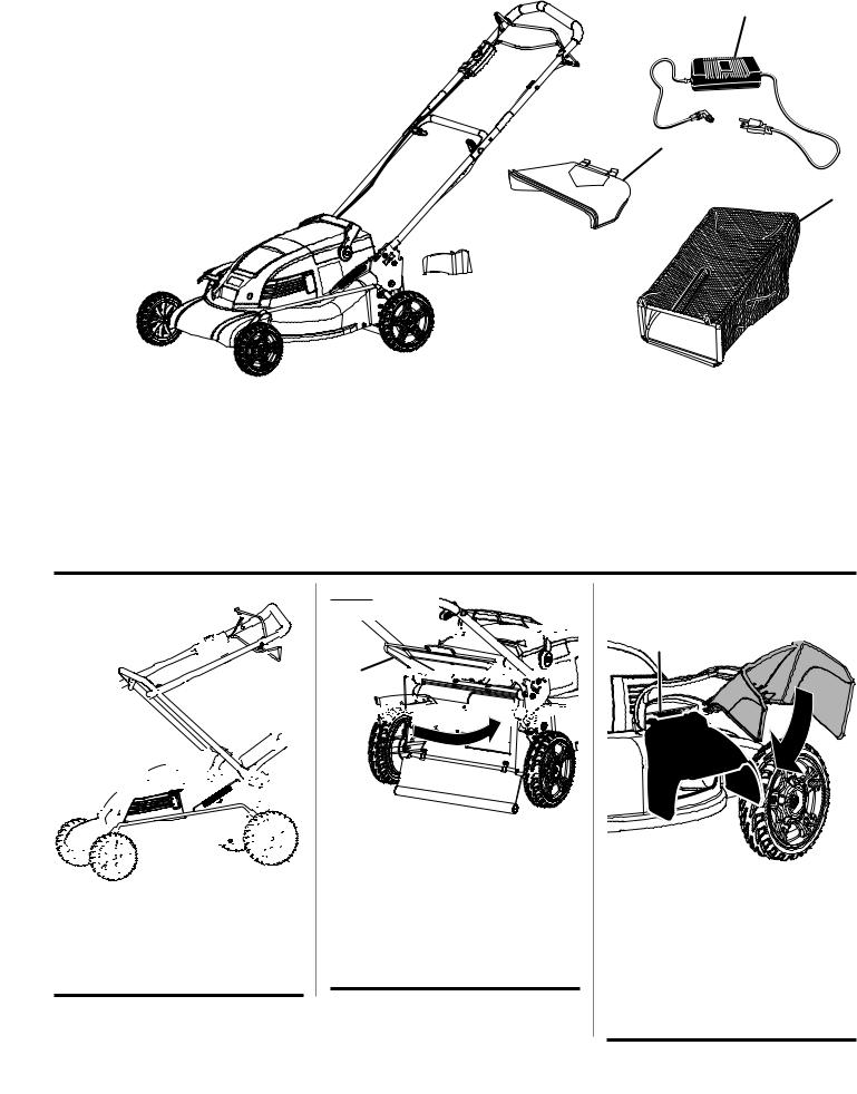
Fig. 1
E
O
A - Motor/blade control assembly (dispositif de commande du moteur/de la lame, conjunto de control del motor/hoja)
B- Battery pack (bloc-pile, paquete de baterías)
C- Battery meter (compteur de piles, medidor de batería)
D- Fuse key (clé-fusible, llave del fusible)
E- Height adjustment lever (levier de réglage de la hauteur, palanca de ajuste de altura)
F- Charger (chargeur, cargador)
|
L |
M |
|
|
|
|
|
F |
|
J |
|
A |
K |
|
|
|
|
|
|
H |
B |
|
|
C |
|
I |
|
|
G
N D
G- Mulching plug (insert broyeur, tapón para trituración)
H- Side discharge deflector (déflecteur d’éjection latérale, deflector de descarga lateral)
I- Grass catcher (collecteur d’herbe, receptor de hierba)
J - Start button (bouton « Start » [démarrer] botón de arranque)
K- Lower bail (green) (anse inférieure [verte], asa inferior [verde])
L- Upper bail (gray) (anse supérieure [grise], asa superior [gris])
M- Handle (poignée, mangos)
N- Fuse key cover/slot (couvercle ou fente de la clé-fusible, cubierta y ranura de la llave del fusible)
O- Side discharge door opening (ouverture d’éjection latérale, abertura de descarga lateral)
Fig. 2
C
B
A
A - Handle knobs (boutons de la poignée, perillas)
B - Lower handle (poignée inférieure, mango inferior)
C - Upper handle (poignée supérieure, mango superior)
Fig. 3
B 


A 


 C
C 


 D
D 


A - Rear discharge door (couvercle d’éjection arrière, puerta de descarga posterior)
B- Handle (poignée inférieure, mango inferior)
C- Mulching plug (insert broyeur, tapón para trituración)
D- Rear discharge opening (ouverture d’éjection arrière, abertura de descarga posterio)
Fig. 4
E D 
 A B
A B 


C
A - Pins (goupilles, pasadores) B - Hooks (crochets, ganchos)
C - Side discharge opening (ouverture d’éjection latérale, abertura de descarga lateral)
D - Side discharge deflector (déflecteur d’éjection latérale, deflector de descarga lateral)
E - Side discharge door (couvercle d’éjection latérale, barra de descarga lateral)
iii

Fig. 5 |
|
|
|
B |
|
B |
|
A |
|
|
|
|
|
|
|
|
|
|
|
A - |
Grass catcher handle (poignée |
|
|
|
|
C |
|
de collecteur d’herbe, mango del |
|
|
|
|
receptor de hierba) |
|
|
|
|
|
|
|
|
|
|
B |
- |
Slots (fentes, ranuras) |
F |
|
|
C - |
Rear door (couvercle d’éjection, |
||
|
|
|
|
puerta de descarga) |
|
E |
D |
D - |
Rear discharge opening |
|
|
F |
|
(ouverture d’éjection latérale, |
|
||
|
|
|
abertura de descarga lateral) |
|
|
|
|
E - |
Door rod (barre de couvercle, |
|
|
|
|
|
|
barra de la puerta) |
|
|
|
F |
- |
Hooks (crochets, ganchos) |
|
Fig. 6
A
C
B
A - Height adjustment lever (levier de réglage de la hauteur, palanca de ajuste de altura)
B- Lowest blade setting (le plus bas réglage de la lame, ajuste más bajo de la hoja)
C- Highest blade setting (le plus haut réglage de la lame, ajustes de cuchilla más alto)
Fig. 7
A 


C
B
A - LEDs (les témoins, DEL)
B- Battery meter (compteur de piles, medidor de batería)
C- Battery receptacle cover (prise ou couvercle de la pile, receptáculo y tapa de la batería)
Fig. 8 |
B |
A
A - Charger (chargeur, cargador)
B- Battery receptacle (prise de la pile, receptáculo de la batería)
Fig. 9 C
A
B
A - Fuse key (clé-fusible, llave del fusible)
B- Fuse key cover/slot (couvercle ou fente de la clé-fusible, cubierta y ranura de la llave del fusible)
C- Motor shroud (enveloppe du moteur, cubierta del motor)
Fig. 10 |
A |
|
|
|
C |
B
A - Upper bail (gray) (anse supérieure [grise], asa superior [gris])
B- Lower bail (green) (anse inférieure [verte], asa inferior [verde])
C- Start button(bouton « Start » [démarrer] botón de arranque)
Fig. 11
15° MAXIMUM 15° MAXIMAL 15° MÁXIMA
iv
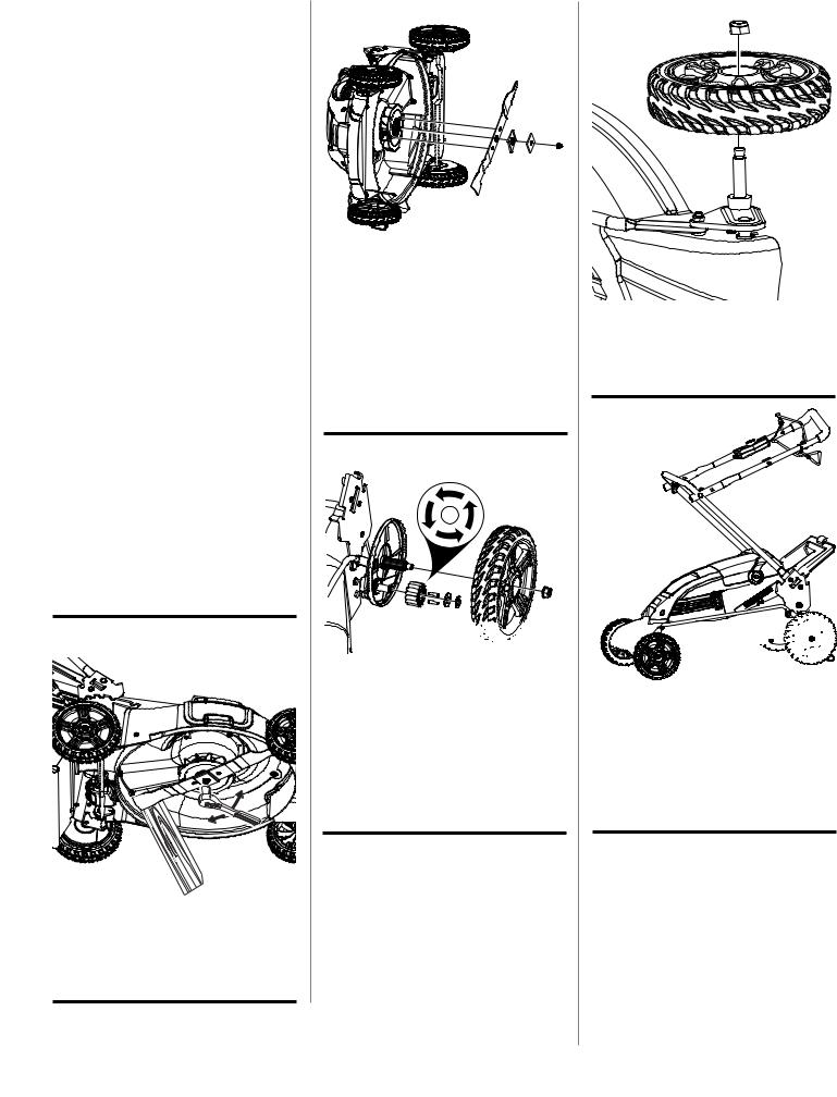
Fig. 12
Fig. 13
B
A
A - Fuse key (clé-fusible, llave del fusible)
B- Reset button (red) (bouton « reset » [rouge], botón de reajuste [rojo])
Fig. 14
A
C  B
B
A - Blade (lame, hoja)
B- Wrench (clé, llave)
C- Block of wood (pièce de bois, bloque de madera)
Fig. 15
C
A
G B
D E F
G
A - Fan assembly (ensemble de ventilateur, conjunto del ventilador)
B- Shaft (arbre, eje)
C- Blade (lame, hoja)
D- Blade insulator (isolant de lame, aislante de hoja)
E- Spacer (entretoise, separador)
F- Blade nut (écrou de lame, tuerca de la hoja)
G- Blade posts (tiges pour lame, montantes de cuchilla)
Fig. 16
G F E D 


 A
A
A - Nut (écrou, tuerca) |
B |
|
B- Wheel (roue, rueda)
C- Dust cover(pare-poussière, tapa contrapolvo)
D- E-ring (clip en E, aro “E”)
E- Washer (rondelle, arandela)
F- Pins (goupilles, pasadores)
G- Wheel gear (engrenage de roue, engranaje de muela)
Fig. 17
A
B
C
A - Hex nut (écrou hexagonal, tuerca hexagonal)
B- Wheel (roulette, rueda)
C- Wheel axle (essieu, eje de la rueda)
Fig. 18 B
C
A
A - Handle knobs (boutons de la poignée, perillas)
B- Upper handle (poignée supérieure, mango superior)
C- Lower handle (poignée inférieure, mango inferior)
v

TABLE OF CONTENTS
TABLE DES MATIÈRES / ÍNDICE DE CONTENIDO
Introduction....................................................................................................................................................................... |
2 |
Introduction / Introducción |
|
Important Safety Instructions......................................................................................................................................... |
3-4 |
Règles de sécurité générales / Reglas de seguridad generales |
|
Symbols......................................................................................................................................................................... |
5-6 |
Symboles / Símbolos |
|
Features............................................................................................................................................................................ |
7 |
Caractéristiques / Características |
|
Assembly........................................................................................................................................................................ |
8-9 |
Assemblage / Armado |
|
Operation..................................................................................................................................................................... |
9-11 |
Utilisation / Funcionamiento |
|
Maintenance............................................................................................................................................................... |
11-12 |
Entretien / Mantenimiento.............................................................................................................................................................. |
12-13 |
Troubleshooting............................................................................................................................................................... |
13 |
Dépannage / Solución de problemas................................................................................................................................................... |
14 |
Warranty.......................................................................................................................................................................... |
14 |
Garantie / Garantía............................................................................................................................................................................... |
15 |
Parts Ordering and Service................................................................................................................................ |
Back Page |
Commande de pièces et réparation / Pedidos de piezas y servicio.......................................................... |
Page arrière / Pág. posterior |
INTRODUCTION
INTRODUCTION / INTRODUCCIÓN
This product has many features for making its use more pleasant and enjoyable. Safety, performance, and dependability have been given top priority in the design of this product making it easy to maintain and operate.
* * *
Ce produit offre de nombreuses fonctions destinées à rendre son utilisation plus plaisante et satisfaisante. Lors de la conception de ce produit, l’accent a été mis sur la sécurité, les performances et la fiabilité, afin d’en faire un outil facile à utiliser et à entretenir.
* * *
Este producto ofrece numerosas características para hacer más agradable y placentero su uso. En el diseño de este producto se ha conferido prioridad a la seguridad, el desempeño y la fiabilidad, por lo cual se facilita su manejo y mantenimiento.
2 — English

IMPORTANT SAFETY INSTRUCTIONS
WARNING:
READ AND UNDERSTAND ALL INSTRUCTIONS.
Failure to follow all instructions listed below and on the machine may result in electric shock, fire, and/or serious personal injury.
READ ALL INSTRUCTIONS
This cutting machine is capable of amputating hands and feet and throwing objects. Failure to observe all safety instructions could result in serious injury or death.
Do not use the lawn mower in damp or wet conditions or operate in the rain.
Keep children away - Keep all bystanders, children, and pets at least 50 ft. away.
Tragic accidents can occur if the operator is not alert to the presence of children. Children are often attracted to the machine and the mowing activity. Never assume that children will remain where you last saw them.
•Keep children out of the mowing area and under the watchful care of a responsible adult other than the operator.
•Be alert and turn mower off if a child enters the area.
•Never allow children to operate the machine.
•Useextracarewhen approaching blind corners,shrubs, trees, or other objects that may block your view of a child.
Wear heavy, long pants, long sleeves, boots, and gloves. Do not wear loose fitting clothing, short pants, sandals, or go barefoot. Do not wear jewelry of any kind.
Keep firm footing and balance. Do not overreach. Overreaching can result in loss of balance.
Do not operate the equipment while barefoot or when wearing sandals or similar lightweight footwear. Wear protective footwear that will protect your feet and improve your footing on slippery surfaces.
Do not leave the mower unattended while running or with the fuse key installed.
Keep hands and feet away from cutting area. Keep clear of the discharge opening at all times.
Operate the lawn mower only in daylight or good artificial light.
Always wear safety glasses with side shields. Everyday glasses have only impact resistant lenses. They are NOT safety glasses. Following this rule will reduce the risk of eye injury. Use face mask if operation is dusty.
Always wear eye protection with side shields marked to comply with ANSI Z87.1. Use face mask if operation is dusty.
Use the right appliance. Do not use the lawn mower for any job except that for which it is intended.
Do not force the lawn mower. It will do the job better and safer at the rate for which it was designed.
Stay alert, watch what you are doing and use common sense when operating the lawn mower. Do not operate the mower while tired or under the influence of drugs, alcohol, or medication. A moment of inattention while operating the lawn mower may result in serious personal injury.
Keep machine in good working condition. Keep blades sharp and guards in place and in working order. Replace damaged or unevenly worn blades before using mower.
Check all nuts, bolts, and screws at frequent intervals for proper tightness to be sure the equipment is in safe working condition.
Stop the motor, wait until the blade comes to a complete stop, and remove the fuse key before cleaning the lawn mower, removing the grass catcher, or unclogging the discharge guard.
When not in use, mower should be stored indoors in a dry, locked up place—out of the reach of children. The fuse key should also be removed and stored in a separate location out of the reach of children.
Do not operate the mower without the entire grass catcher, discharge guard, rear guard, or other safety protective devices in place and working.
Follow manufacturer’s instructions for proper operation and installation of accessories. Only use accessories approved by the manufacturer.
Clear the work area before each use. Remove all objects such as rocks, sticks, metal, wire, bones, toys, or other objects which can be thrown by the blade.Stay behind the handle when the motor is running.
Avoid holes, ruts, bumps, rocks, property stakes, or other hidden objects. Uneven terrain could cause a slip and fall accident.
Do not mow near drop-offs, ditches, or embankments.
Mowacrossthefaceofslopes, never up and down.Exercise extreme caution when changing direction on slopes.
Plan your mowing pattern to avoid discharge of material toward roads, sidewalks, bystanders and the like. Also, avoid discharging material against a wall or obstruction, which may cause the material to ricochet back toward the operator.
Do not mow on wet grass or excessively steep slopes.
Poor footing could cause a slip and fall accident. Walk, never run.
Use extra care when approaching blind corners, shrubs, trees, or other objects that may block your view.
Do not pull the mower backward unless absolutely necessary. If you must back the mower away from a wall or obstruction, first look down and behind to avoid tripping or pulling the mower over your feet.
3 — English

IMPORTANT SAFETY INSTRUCTIONS
Never direct discharged material toward anyone. Avoid discharging material against a wall or obstruction. Material may ricochet back toward the operator. Stop the blade when crossing gravel surfaces.
Objects struck by the lawn mower blade can cause severe injuries to persons. The lawn should always be carefully examined and cleared of all objects prior to each mowing.
If the lawn mower strikes a foreign object, follow these steps:
•Stop the lawn mower by releasing the upper bail, wait until the blade comes to a complete stop, and then remove fuse key.
•Thoroughly inspect the mower for any damage.
•Replace the blade if it is damaged in any way. Repair any damage before restarting and continuing to operate the mower.
Stop the motor, wait until the blade comes to a complete stop, and remove fuse key before unclogging the chute. The cutting blade continues to rotate for a few seconds after the motor is shut off. Never place any part of the body in the blade area until you are sure the blade has stopped rotating.
If the mower should start to vibrate abnormally, stop the motor and check immediately for the cause. Replace the blade if it is unevenly worn or damaged in any way. Vibration is generally a warning of trouble.
Service on the product must be performed by qualified repair personnel only. Service or maintenance performed by unqualified personnel could result in injury to the user or damage to the product.
Use only authorized replacement parts when servicing the product. Use of unauthorized parts may create a risk of serious injury to the user, or damage to the product.
Do not place battery tools or their batteries near fire or heat.
This will reduce the risk of explosion and possibly injury.
Do not open or mutilate battery (ies). Released electrolyte is corrosive and may cause damage to the eyes or skin.
It may be toxic if swallowed.
If electrolyte contacts the skin, wash it off immediately with water.
If electrolyte contacts the eyes, flush thoroughly and immediately with water. Seek medical attention.
SAFETY RULES FOR CHARGER
Use of an attachment not recommended or sold by the battery charger manufacturer may result in a risk of fire, electric shock, or injury to persons. Following this rule will reduce the risk of electric shock, fire, or serious personal injury.
Do not service mower with fuse key or charger installed.
Do not use the charger when the ambient temperature is above 40°C or below 0°C.
Do not operate charger with a damaged cord or plug, which could cause shorting and electric shock. If damaged, have the charger replaced by authorized service personnel.
Do not operate charger if it has received a sharp blow, been dropped, or otherwise damaged in any way. Take it to an authorized service center for electrical check to determine if the charger is in good working order.
Unplug charger from outlet before attempting any maintenance or cleaning to reduce the risk of electric shock.
Disconnect charger from the power supply when not in use to prevent damage to the charger during a power surge.
Risk of electric shock. Do not touch uninsulated portion of output connector or uninsulated battery terminal.
Do not expose charger to wet or damp conditions. Water entering charger will increase the risk of electric shock.
Make sure cord is located so that it will not be stepped on, tripped over, come in contact with sharp edges or moving parts or otherwise subjected to damage or stress. This will reduce the risk of accidental falls, which could cause injury, and damage to the cord, which could result in electric shock.
Keep cord and charger away from heat to prevent damage to housing or internal parts.
Do not let gasoline, oils, petroleum-based products, etc. come in contact with plastic parts. They contain chemicals that can damage, weaken, or destroy plastic.
An extension cord should not be used for the charger unless absolutely necessary. Use of improper extension cord could result in a risk of fire and electric shock. If extension cord must be used, make sure:
a.That pins on plug of extension cord are the same number, size and shape as those of plug on charger.
b.That extension cord is properly wired and in good electrical condition; and
c.That wire size is large enough for AC ampere rating of charger as specified below:
Cord Length (Feet) |
25' |
50' |
100' |
Cord Size (AWG) |
16 |
16 |
16 |
NOTE: AWG = American Wire Gauge
Save these instructions. Refer to them frequently and use them to instruct others who may use this product. If you loan someone this tool, loan them these instructions also.
4 — English
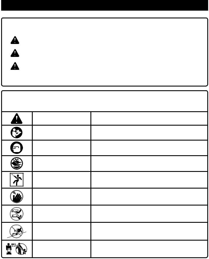
SYMBOLS
The following signal words and meanings are intended to explain the levels of risk associated with this product.
SYMBOL |
SIGNAL |
MEANING |
|
|
|
|
DANGER: |
Indicates an imminently hazardous situation, which, if not avoided, will result |
|
in death or serious injury. |
|
|
|
|
|
|
|
|
WARNING: |
Indicates a potentially hazardous situation, which, if not avoided, could result |
|
in death or serious injury. |
|
|
|
|
|
|
|
|
CAUTION: |
Indicates a potentially hazardous situation, which, if not avoided, may result in |
|
minor or moderate injury. |
|
|
|
|
|
|
|
|
CAUTION: |
(Without Safety Alert Symbol) Indicates a situation that may result in property |
|
damage. |
|
|
|
Some of the following symbols may be used on this product. Please study them and learn their meaning. Proper interpretation of these symbols will allow you to operate the product better and safer.
SYMBOL |
NAME |
DESIGNATION/EXPLANATION |
|
Safety Alert |
Indicates a potential personal injury hazard. |
|
Read Operator’s Manual |
To reduce the risk of injury, user must read and understand |
|
operator’s manual before using this product. |
|
|
|
|
|
Eye Protection |
Always wear eye protection with side shields marked to comply |
|
with ANSI Z87.1 |
|
|
|
|
|
Wet Conditions Alert |
Do not expose to rain or use in damp locations. |
|
Electric Shock |
Failure to use in dry conditions and to observe safe practices can |
|
result in electric shock. |
|
|
|
|
|
Keep Hands and Feet Away |
Keep hands and feet away from blade and cutting area. |
|
No Reach |
Do not reach hands or feet under mower deck. |
|
No Slope |
Do not operate on inclines greater than 15º. Mow across the face |
|
of slopes, never up and down. |
|
|
|
|
|
Keep Children and |
Keep all children and bystanders at least 100 ft. away |
|
Bystanders Away |
|
|
|
5 — English

SYMBOLS
Some of the following symbols may be used on this product. Please study them and learn their meaning. Proper interpretation of these symbols will allow you to operate the product better and safer.
SYMBOL |
NAME |
DESIGNATION/EXPLANATION |
|
|
|
|
|
This product uses lead-acid (Pb) batteries. Local, state, or federal |
|
Recycle Symbol |
laws may prohibit disposal of batteries in ordinary trash. Consult |
|
your local waste authority for information regarding available re- |
|
|
|
|
|
|
cycling and/or disposal options. |
|
|
|
V |
Volts |
Voltage |
|
|
|
A |
Amperes |
Current |
|
|
|
Hz |
Hertz |
Frequency (cycles per second) |
|
|
|
W |
Watt |
Power |
|
|
|
hrs |
Hours |
Time |
|
|
|
CALIFORNIA PROPOSITION 65
 WARNING:
This product and substances that may become airborne from its use may contain chemicals, including lead, known to the State of California to cause cancer, birth defects, or other reproductive harm. Wash hands after handling.
6 — English
FEATURES
PRODUCT SPECIFICATIONS
Battery................. |
48 Volt, 10 A/hr sealed maintenance free |
No-load Speed....................................... |
3,400 r/min. (RPM) |
Cutting Path................................................................ |
20 in. |
Height Adjustments............................. |
1-1/2 in. to 3-3/4 in. |
Wheel Size............................................ |
7 in. front, 8 in. rear |
Weight......................................................................... |
87 lb. |
KNOW YOUR LAWN MOWER
See Figure 1.
The safe use of this product requires an understanding of the information on the product and in this operator’s manual as well as a knowledge of the project you are attempting. Before use of this product, familiarize yourself with all operating features and safety rules.
BATTERY METER
The battery meter measures the amount of charge remaining in the battery.
FUSE KEY
The fuse key must be inserted before the mower can be started.
GRASS CATCHER
The grass catcher collects grass clippings and prevents them from being discharged across your lawn as you mow.
HEIGHT ADJUSTMENT LEVER
The height adjustment lever provides cutting height adjustments.
MOTOR/BLADE CONTROL ASSEMBLY
The motor/blade control, located on the upper handle of the mower, engages and disengages the motor and blade.
MULCHING PLUG
Your mower is equipped with a mulching plug that covers the rear discharge opening, which allows the mower blade to cut and recut for finer clippings.
SELF-PROPELLED FEATURE
Pulling the lower bail upward to meet the handle turns on the self-propelled feature of your mower.
SIDE DISCHARGE DEFLECTOR
Use the side discharge deflector on your mower when the grass is too high to mulch or when side discharging is preferred. The grass clippings produced when using the side discharge deflector are noticeably larger than those produced when using the mulching plug and side mulching plate.
SIDE DISCHARGE DOOR
Your mower is equipped with a door that covers the side discharge opening, which allows the mower blade to cut and recut the grass for finer clippings.
7 — English

ASSEMBLY
UNPACKING
This product requires assembly.
nCarefully remove the product and any accessories from the box. Make sure that all items listed in the packing list are included.
 WARNING:
Do not use this product if any parts on the Packing List are already assembled to your product when you unpack it. Parts on this list are not assembled to the product by the manufacturer and require customer installation. Use of a product that may have been improperly assembled could result in serious personal injury.
nInspect the product carefully to make sure no breakage or damage occurred during shipping.
nDo not discard the packing material until you have carefully inspected and satisfactorily operated the product.
nIf any parts are damaged or missing, please call 1-800-860-4050 for assistance.
PACKING LIST
Mower
Fuse Key
Side Discharge Deflector
Mulching Plug
Grass Catcher
Charger
Operator’s Manual
 WARNING:
If any parts are damaged or missing, do not operate this product until the parts are replaced. Use of this product with damaged or missing parts could result in serious personal injury.
 WARNING:
Do not attempt to modify this product or create accessories not recommended for use with this product. Any such alteration or modification is misuse and could result in a hazardous condition leading to possible serious personal injury.
 WARNING:
Do not insert fuse key until assembly is complete and you are ready to mow. Failure to comply could result in accidental starting and possible serious personal injury.
 WARNING:
To prevent accidental starting, do not make any adjustments or installations with the fuse key inserted. Accidental starting of the mower during assembly could result in serious personal injury.
 WARNING:
Never operate the mower without the proper safety devices in place and working. Never operate the mower with damaged safety devices. Operating the mower with missing or damaged parts can result in serious personal injury.
UNFOLDING AND ADJUSTING HANDLE ASSEMBLY
See Figure 2.
Fully loosen the handle knobs on both sides of the handle by rotating counterclockwise.
Pull up and back on the upper handle to raise the handle into operating position. Make certain the handles snap into place securely.
Tighten the handle knobs on both sides of the handle to secure by rotating clockwise.
Avoid pinching or trapping any cables in handle assembly.
INSTALLING THE MULCHING PLUG (FOR MULCHING OPERATION)
See Figure 3.
NOTE: When using the mulching plug, do not install either the side discharge deflector or the grass catcher.
Lift and hold up the rear discharge door.
Grasp the mulching plug by its handle and insert it at a slight angle, as shown.
Push the mulching plug securely into place.
Ensure side discharge door is down.
Lower the rear discharge door.
INSTALLING SIDE DISCHARGE DEFLECTOR (FOR SIDE DISCHARGE OPERATION)
See Figure 4.
NOTE: When using the side discharge deflector, do not install the grass catcher. The mulching plug should remain installed.
Lift the side discharge door.
Align the hooks on the deflector with the hinge rod on the underside of the door.
8 — English

ASSEMBLY
Lower the deflector until the hooks are secured on the mulch door hinge rod.
Release the deflector and side discharge door.
INSTALLING THE GRASS CATCHER (FOR REAR BAGGING OPERATION)
See Figure 5.
NOTE: When using the grass catcher, do not install either the side discharge deflector or the mulching plug. Also, ensure side discharge door is closed securely.
Lift the rear discharge door.
Lift the grass catcher by its handle and place under the rear door so that the hooks on the grass catcher frame are seated into the slots in the handle bracket.
Release the rear door. When installed correctly, the hooks on the grass catcher will rest securely in the slots on the handle brackets.
SETTING BLADE HEIGHT
See Figure 6.
When shipped, the wheels on the mower are set to a low-cutting position. Before using the mower for the first time, raise the cutting position to the height best suited for your lawn. The average lawn should be between 1-1/2 in. to 2 in. during cool months and between 2 in. and 3-1/4 in. during hot months.
To adjust the blade height:
To raise the blade height, grasp the height adjustment lever and move it toward the back of the mower.
To lower the blade height, grasp the height adjustment lever and move it toward the front of the mower.
OPERATION
WARNING: |
BATTERY METER |
See Figure 7. |
Do not allow familiarity with products to make you careless. Remember that a careless fraction of a second is sufficient to inflict serious injury.
 WARNING:
Always wear eye protection with side shields marked to comply with ANSI Z87.1. Failure to do so could result in objects being thrown into your eyes resulting in possible serious injury.
 WARNING:
Do not use any attachments or accessories not recommended by the manufacturer of this product. The use of attachments or accessories not recommended can result in serious personal injury.
 WARNING:
Always inspect mower for missing or damaged parts and blade for damage, uneven, or excessive wear prior to use.
Use of the mower with damaged or missing parts may result in serious personal injury.
APPLICATIONS
You may use this product for the purpose listed below: Mowing your lawn
Since the mower battery is shipped in a low charge condition, the battery must be charged before use. The battery has four LED lights to indicate battery capacity. These lights will illuminate when the button is pressed.
If four LED lights illuminate, the battery is 100% charged and ready for use. Three lights indicate a 50-80% charge. Two lights indicate a 30-50% charge.
If one light illuminates, the battery will soon require charging. It is recommended that the battery be charged at this point. The battery is at 5-30% charge when one light illuminates.
If no lights illuminate, the battery must be charged IMMEDIATELY before use. There is less than 5% of battery charge remaining if none of the lights come on.
NOTE: When none of the lights are on, you must stop the mower and charge the battery immediately, or it will reduce the life of the battery.
CHARGING THE BATTERY PACK
See Figures 7 - 8.
 WARNING:
Always remove the fuse key and store it in a separate location out of the reach of children when the mower is charging or not in use. Failure to remove the fuse key may result in accidental starting or unauthorized use and cause serious personal injury.
The lawn mower comes with a maintenance-free, spill-free, sealed 48 Volt battery pack.
9 — English

OPERATION
The battery should be charged in a cool, dry place. The battery charger should be operated in temperatures between 23°F and 104°F.
Charge the battery pack only with the charger provided.
The battery pack may be charged while it is connected to the mower, or while it is disconnected from the mower.
Allow at least 10-12 hours of charge time before initial use of the mower.
The charger may remain connected to the battery pack any time the mower is not in use.
To improve battery life, store battery indoors in a controlled climate.
The battery does not have to be fully discharged before recharging.
Two to three initial charging/discharging cycles may be required to achieve maximum run time/capacity.
When fully charged, the battery can be safely stored in temperatures down to -40°F for a period of up to two weeks, before it requires charging.
To charge:
Make sure the power supply is normal household voltage,
120 volts, AC only, 60 Hz.
Remove the fuse key and store in separate location out of reach of children.
Remove the cover from the battery receptacle.
Plug the charger connector into the receptacle on the mower battery.
Insert the 120 volt plug of the charger into the wall receptacle.
The red light on the charger should come on, indicating you have power and the battery is being charged. The red light should go off when charging is complete. A fully discharged mower will charge in approximately 10-12 hours.
When charging is complete, disconnect the charger from the battery, and replace the receptacle cover.
STARTING/STOPPING THE MOWER
See Figures 9 - 10.
Insert the fuse key into the slot on the motor/shroud assembly.
Press and hold the start button. Pull the upper bail toward the handle and release the button to start the mower.
To stop the mower, release the upper bail.
MOWING TIPS
See Figure 11.
Make sure the lawn is clear of stones, sticks, wires, and other objects that could damage the lawn mower blades or motor. Do not mow over property stakes or other metal posts. Such objects could be accidentally thrown by the mower in any direction and cause serious personal injury to the operator and others.
For a healthy lawn, always cut off one-third or less of the total length of the grass.
When cutting heavy grass, reduce walking speed to allow for more effective cutting and a proper discharge of the clippings.
Do not cut wet grass. It will stick to the underside of the deck and prevent proper bagging or mulching of grass clippings.
New or thick grass may require a narrower cut or a higher cutting height.
Clean the underside of the mower deck after each use to remove grass clippings, leaves, dirt, and any other accumulated debris.
NOTE: Always stop mower, allow blades to completely stop, and remove the fuse key before cleaning unerneath the mower.
SLOPE OPERATION
 WARNING:
Slopes are a major factor related to slip and fall accidents that can result in severe injury. Operation on slopes requires extra caution. If you feel uneasy on a slope, do not mow it. For your safety, do not attempt to mow slopes greater than 15 degrees.
Mow across the face of slopes, not up and down. Exercise extreme caution when changing direction on slopes.
Watch for holes, ruts, rocks, hidden objects, or bumps which can cause you to slip or trip. Tall grass can hide obstacles. Remove all objects such as rocks, tree limbs, etc., which could be tripped over or thrown by the blade.
Always be sure of your footing. A slip and fall can cause serious personal injury. If you feel you are losing your balance, release the upper bail immediately.
Do not mow near drop-offs, ditches, or embankments; you could lose your footing or balance.
SELF-PROPELLED MOWING |
EMPTYING THE GRASS CATCHER |
See Figures 9 - 10. |
See Figure 12. |
Once the mower has been started, the self-propelled feature is engaged by pulling the lower bail upward to meet the handle.
To disengage the self-propelled feature, release the lower bail.
Stop mower, allow blades to completely stop, and remove fuse key.
Lift the rear door.
10 — English

OPERATION
Lift the grass catcher by its handle to remove from mower.
Empty grass clippings.
Lift the rear door and reinstall the grass catcher as described earlier in this manual.
RESETTING THE FUSE
See Figure 13.
If the motor stops while you are cutting grass, you may need to reset the fuse. Press the reset button on the fuse key and try restarting the motor.
MAINTENANCE
 WARNING:
Before performing any maintenance, make sure the mower battery and fuse key are removed to avoid accidental starting and possible serious personal injury.
 WARNING:
When servicing, use only authorized replacement parts. Use of any other parts may create a hazard or cause product damage.
 WARNING:
Always wear eye protection with side shields marked to comply with ANSI Z87.1. Failure to do so could result in objects being thrown into your eyes resulting in possible serious injury.
GENERAL MAINTENANCE
Avoid using solvents when cleaning plastic parts. Most plastics are susceptible to damage from various types of commercial solvents and may be damaged by their use. Use clean cloths to remove dirt, dust, oil, grease, etc.
 WARNING:
Do not at any time let brake fluids, gasoline, petroleumbased products, penetrating oils, etc., come in contact with plastic parts. Chemicals can damage, weaken, or destroy plastic which may result in serious personal injury.
Periodically check all nuts and bolts for proper tightness to ensure safe operation of the mower.
Remove any buildup of grass and leaves on or around the motor cover. Wipe the mower clean with a dry cloth occasionally. Do not use water.
LUBRICATION
All of the bearings in this product are lubricated with a sufficient amount of high grade lubricant for the life of the unit under normal operating conditions. Therefore, no further bearing lubrication is required.
 WARNING:
Always protect hands by wearing heavy gloves and/or wrapping the cutting edges of the blade with rags and other material when performing blade maintenance. Contact with the blade could result in serious personal injury.
REPLACING THE CUTTING BLADE
See Figure 14 - 15.
NOTE: Only use authorized replacement blades.
Stop the motor and remove the fuse key. Allow blade to come to a complete stop.
Remove the battery pack.
Turn the mower on its side.
Wedge a block of wood between the blade and mower deck to prevent the blade from turning.
Loosen the blade nut by turning it counterclockwise (as viewed from bottom of mower) using a 15 mm wrench or socket (not provided).
Remove the blade nut, spacer, blade insulator, and blade.
Make certain the fan assembly is pushed completely against the motor shaft.
Place the new blade on the shaft against the fan assembly. Ensure blade is properly seated with shaft going through center blade hole and the two blade posts inserted into their respective holes on the blade. Make sure it is installed with the curved ends pointing up toward the mower deck and not down toward the ground. When seated properly, the blade should be flat against the fan assembly.
Replace the blade insulator and spacer, then thread the blade nut on the shaft and finger tighten.
NOTE: Make certain all parts are replaced in the exact order in which they were removed.
Torque the blade nut down clockwise using a torque wrench (not provided) to ensure the bolt is properly tightened. The recommended torque for the blade nut is 350400 in. lbs.
11 — English
 Loading...