


OPERATOR’S MANUAL
12 in. DIGITAL DRILL PRESS
DP121l
Your drill press has been engineered and manufactured to our high standard for dependability, ease of operation, and operator safety. When properly cared for, it will give you years of rugged, trouble-free performance.
 WARNING: To reduce the risk of injury, the user must read and understand the operator’s manual before using this product.
Thank you for your purchase.
SAVE THIS MANUAL FOR FUTURE REFERENCE

|
TABLE OF CONTENTS |
Introduction...................................................................................................................................................................... |
2 |
Warranty........................................................................................................................................................................... |
2 |
General Safety Rules..................................................................................................................................................... |
3-4 |
Specific Safety Rules....................................................................................................................................................... |
5 |
Symbols........................................................................................................................................................................ |
6-7 |
Electrical........................................................................................................................................................................... |
8 |
Glossary of Terms............................................................................................................................................................ |
9 |
Features.................................................................................................................................................................... |
10-11 |
Tools Needed................................................................................................................................................................. |
11 |
Loose Parts.................................................................................................................................................................... |
12 |
Assembly................................................................................................................................................................... |
13-17 |
Operation.................................................................................................................................................................. |
18-20 |
Adjustments................................................................................................................................................................... |
21 |
Maintenance................................................................................................................................................................... |
22 |
Troubleshooting.............................................................................................................................................................. |
23 |
Parts Ordering / Service.................................................................................................................................... |
Back Page |
|
INTRODUCTION |
This tool has many features for making its use more pleasant and enjoyable. Safety, performance, and dependability have been given top priority in the design of this product making it easy to maintain and operate.
warranty
RYOBI® POWER TOOL - LIMITED TWO YEAR WARRANTY AND 30 DAY EXCHANGE POLICY
Techtronic Industries North America, Inc., warrants its RYOBI® power tools with the following conditions:
30-DAY EXCHANGE POLICY: During the first 30 days after date of purchase, you may either request service under this warranty or you may exchange any RYOBI® power tool which does not work properly due to defective workmanship or materials by returning the power tool to the dealer from which it was purchased. To receive a replacement power tool or requested warranty service, you must present proof of purchase and return all original equipment packaged with the original product. The replacement power tool will be covered by the limited warranty for the balance of the two year period from the date of the original purchase.
WHAT THIS WARRANTY COVERS: This warranty covers all defects in workmanship or materials in your RYOBI® power tool for a period of two years from the date of purchase. With the exception of batteries, power tool accessories are warranted for ninety (90) days. Batteries are warranted for two years.
HOW TO GET SERVICE: Just return the power tool, properly packaged and postage prepaid, to an Authorized Service Center. You can obtain the location of the Service Center nearest you by contacting a service representative at Techtronic Industries North America, Inc., P.O. Box 1207, Anderson, SC 29622-1207, by calling 1-800-525-2579 or by logging on to www.ryobitools.com. When you request warranty service, you must also present proof of purchase documentation, which includes the date of purchase (for example, a bill of sale). We will repair any faulty workmanship, and either repair or replace any defective part, at our option. We will do so without any charge to you. We will complete the work in a reasonable time, but, in any case, within ninety (90) days or less.
WHAT’S NOT COVERED: This warranty applies only to the original purchaser at retail and may not be transferred. This warranty only covers defects arising under normal usage and does not cover any malfunction, failure or defects resulting from misuse, abuse, neglect, alteration, modification or repairs by other than Authorized Service Centers. Techtronic Industries North America, Inc. makes no warranties, representations or promises as to the quality or performance of its power tools other than those specifically stated in this warranty.
ADDITIONAL LIMITATIONS: Any implied warranties granted under state law, including warranties of merchantability or fitness for a particular purpose, are limited to two years from the date of purchase. Techtronic Industries North America, Inc. is not responsible for direct, indirect, or incidental damages, so the above limitations and exclusions may not apply to you. This warranty gives you specific legal rights, and you may also have other rights which vary from state to state.

GENERAL SAFETY RULES
WARNING:
Read and understand all instructions. Failure to follow all instructions listed below, may result in electric shock, fire and/or serious personal injury.
READ ALL INSTRUCTIONS
KNOW YOUR POWER TOOL. Read the operator’s manual carefully. Learn the applications and limitations as well as the specific potential hazards related to this tool.
GUARD AGAINST ELECTRICAL SHOCK BY PREVENTING BODY CONTACT WITH GROUNDED SURFACES. For example: pipes, radiators, ranges, refrigerator enclosures.
KEEP GUARDS IN PLACE and in good working order.
REMOVE ADJUSTING KEYS AND WRENCHES. Form habit of checking to see that keys and adjusting wrenches are removed from tool before turning it on.
KEEP WORK AREA CLEAN. Cluttered areas and benches invite accidents. DO NOT leave tools or pieces of wood on the tool while it is in operation.
DO NOT USE IN DANGEROUS ENVIRONMENTS. Do not use power tools in damp or wet locations or expose to rain. Keep the work area well lit.
KEEP CHILDREN AND VISITORS AWAY. All visitors should wear safety glasses and be kept a safe distance from work area. Do not let visitors contact tool or extension cord while operating.
MAKE WORKSHOP CHILDPROOF with padlocks, master switches, or by removing starter keys.
DON’T FORCE THE TOOL. It will do the job better and safer at the feed rate for which it was designed.
USE THE RIGHT TOOL. Do not force the tool or attachment to do a job for which it was not designed.
USE THE PROPER EXTENSION CORD. Make sure your extension cord is in good condition. Use only a cord heavy enough to carry the current your product will draw. An undersized cord will cause a drop in line voltage resulting in loss of power and overheating. A wire gauge size (A.W.G.) of at least 16 is recommended for an extension cord 50 feet or less in length. If in doubt, use the next heavier gauge. The smaller the gauge number, the heavier the cord.
DRESS PROPERLY. Do not wear loose clothing, gloves, neckties, or jewelry that can get caught and draw you into moving parts. Rubber gloves and nonskid footwear are recommended when working outdoors. Also wear protective hair covering to contain long hair.
ALWAYS WEAR SAFETY GLASSES WITH SIDE SHIELDS. Everyday eyeglasses have only impactresistant lenses, they are NOT safety glasses.
SECURE WORK. Use clamps or a vise to hold work when practical, it is safer than using your hand and frees both hands to operate the tool.
DO NOT OVERREACH. Keep proper footing and balance at all times.
MAINTAIN TOOLS WITH CARE. Keep tools sharp and clean for better and safer performance. Follow instructions for lubricating and changing accessories.
DISCONNECT TOOLS. When not in use, before servicing, or when changing attachments, blades, bits, cutters, etc., all tools should be disconnected from power source.
AVOID ACCIDENTAL STARTING. Be sure switch is off when plugging in any tool.
USE RECOMMENDED ACCESSORIES. Consult the operator’s manual for recommended accessories. The use of improper accessories may result in injury.
NEVER STAND ON TOOL. Serious injury could occur if the tool is tipped or if the cutting tool is unintentionally contacted.
CHECK DAMAGED PARTS. Before further use of the tool, a guard or other part that is damaged should be carefully checked to determine that it will operate properly and perform its intended function. Check for alignment of moving parts, binding of moving parts, breakage of parts, mounting and any other conditions that may affect its operation. A guard or other part that is damaged must be properly repaired or replaced by an authorized service center to avoid risk of personal injury.
USE THE RIGHT DIRECTION OF FEED. Feed work into a blade, cutter, or sanding spindle against the direction or rotation of the blade, cutter, or sanding spindle only.
NEVER LEAVE TOOL RUNNING UNATTENDED. TURN THE POWER OFF. Don’t leave tool until it comes to a complete stop.
PROTECT YOUR LUNGS. Wear a face or dust mask if the cutting operation is dusty.
PROTECT YOUR HEARING. Wear hearing protection during extended periods of operation.
DO NOT ABUSE CORD. Never carry tool by the cord or yank it to disconnect from receptacle. Keep cord from heat, oil, and sharp edges.
USE OUTDOOR EXTENSION CORDS. When tool is used outdoors, use only extension cords with approved ground connection that are intended for use outdoors and so marked.
STAY ALERT AND EXERCISE CONTROL. Watch what you are doing and use common sense. Do not operate tool when you are tired. Do not rush.

GENERAL SAFETY RULES
DO NOT USE TOOL IF SWITCH DOES NOT TURN IT ON AND OFF. Have defective switches replaced by an authorized service center.
ALWAYS TURN SWITCH OFF before disconnecting it to avoid accidental starting.
NEVER USE IN AN EXPLOSIVE ATMOSPHERE. Normal sparking of the motor could ignite fumes.
INSPECT TOOL CORDS PERIODICALLY. If damaged, have repaired by a qualified service technician at an authorized service facility. The conductor with insulation having an outer surface that is green with or without yellow stripes is the equipment-grounding conductor. If repair or replacement of the electric cord or plug is necessary, do not connect the equipment-grounding conductor to a live terminal. Repair or replace a damaged or worn cord immediately. Stay constantly aware of cord location and keep it well away from the rotating blade.
INSPECT EXTENSION CORDS PERIODICALLY and replace if damaged.
GROUND ALL TOOLS. If tool is equipped with threeprong plug, it should be plugged into a three-hole electrical receptacle.
Use only correct electrical devices: 3-wire extension cords that have 3-prong grounding plugs and 3-pole receptacles that accept the tool’s plug.
KEEP TOOL DRY, CLEAN, AND FREE FROM OIL AND GREASE. Always use a clean cloth when cleaning. Never use brake fluids, gasoline, petroleum-based products, or any solvents to clean tool.
NEVER START A TOOL WHEN ANY ROTATING
COMPONENT IS IN CONTACT WITH THE WORKPIECE.
DO NOT OPERATE A TOOL WHILE UNDER THE INFLUENCE OF DRUGS, ALCOHOL, OR ANY MEDICATION.
WHEN SERVICING use only identical replacement parts. Use of any other parts may create a hazard or cause product damage.
USE ONLY RECOMMENDED ACCESSORIES listed in this manual or addendums. Use of accessories that are not listed may cause the risk of personal injury. Instructions for safe use of accessories are included with the accessory.

SPECIFIC SAFETY RULES
KEEP BITS CLEAN AND SHARP. Sharp bits minimize stalling. Dirty and dull bits may cause misalignment of the material and possible operator injury.
KEEP HANDS AWAY FROM WORK AREA. Keep hands away from the bit. Restrain any loose clothing, jewelry, long hair, etc., that may become entangled in the bit.
ALWAYS CLAMP WORKPIECE AND BRACE AGAINST COLUMN TO PREVENT ROTATION. Never use your hand to hold the object while drilling.
USE RECOMMENDED SPEED FOR DRILL ACCESSORY AND WORKPIECE MATERIAL.
BE SURE DRILL BIT OR CUTTING TOOL IS SECURELY LOCKED IN THE CHUCK.
BE SURE CHUCK KEY IS REMOVED from the chuck before connecting to power source or turning power
ON.
ADJUST THE TABLE OR DEPTH STOP TO AVOID DRILLING INTO THE TABLE. Shut off the power, remove the drill bit, and clean the table before leaving machine.
AVOID direct eye exposure when using the laser guide.
Always ensure the laser beam is aimed at a surface withou reflective properties.
Shiny reflective materials are not suitable for laser use.
NEVER PLACE YOUR FINGERS IN A POSITION WHERE THEY COULD CONTACT THE DRILL or other cutting tool if the workpiece should unexpectedly shift.
NEVER PERFORM ANY OPERATION by moving the head or table with respect to one another. Do not turn the motor switch ON or start any operation before checking that the head and table support lock handle is clamped tight to column and head and table support collars are correctly positioned.
BEFORE ENGAGING THE POWER SWITCH, MAKE SURE THE BELT GUARD IS DOWN AND THE CHUCK IS INSTALLED PROPERLY.
LOCK THE MOTOR SWITCH OFF WHEN LEAVING THE DRILL PRESS. Do not perform layout, assembly, or set-up work on the table while the cutting tool is rotating, switched on, or connected to a power source.
SAVE THESE INSTRUCTIONS. Refer to them frequently and use to instruct other users. If you loan someone this tool, loan them these instructions also.
WARNING:
Some dust created by power sanding, sawing, grinding, drilling, and other construction activities contains chemicals known to cause cancer, birth defects or other reproductive harm. Some examples of these chemicals are:
•lead from lead-based paints,
•crystalline silica from bricks and cement and other masonry products, and
•arsenic and chromium from chemically-treated lumber.
Your risk from these exposures varies, depending on how often you do this type of work. To reduce your exposure to these chemicals, work in a well ventilated area, and work with approved safety equipment, such as those dust masks that are specially designed to filter out microscopic particles.

SYMBOLS
Some of the following symbols may be used on this tool. Please study them and learn their meaning. Proper interpretation of these symbols will allow you to operate the tool better and safer.
SYMBOL |
NAME |
DESIGNATION/EXPLANATION |
V |
Volts |
Voltage |
A |
Amperes |
Current |
Hz |
Hertz |
Frequency (cycles per second) |
W |
Watt |
Power |
min |
Minutes |
Time |
|
Alternating Current |
Type of current |
|
Direct Current |
Type or a characteristic of current |
no |
No Load Speed |
Rotational speed, at no load |
|
Class II Construction |
Double-insulated construction |
.../min |
Per Minute |
Revolutions, strokes, surface speed, orbits etc., per minute |
|
Wet Conditions Alert |
Do not expose to rain or use in damp locations. |
|
Read The Operator’s Manual |
To reduce the risk of injury, user must read and understand |
|
operator’s manual before using this product. |
|
|
|
|
|
Eye Protection |
Always wear safety goggles or safety glasses with side shields |
|
and a full face shield when operating this product. |
|
|
|
|
|
Safety Alert |
Precautions that involve your safety. |
|
No Hands Symbol |
Failure to keep your hands away from the blade will result in |
|
serious personal injury. |
|
|
|
|
|
Hot Surface |
To reduce the risk of injury or damage, avoid contact with |
|
any hot surface. |
|
|
|

SYMBOLS
The following signal words and meanings are intended to explain the levels of risk associated with this product.
SYMBOL |
SIGNAL |
MEANING |
|
|
|
|
|
|
DANGER: |
Indicates an imminently hazardous situation, which, if not avoided, will |
|
|
result in death or serious injury. |
|
|
|
|
|
|
|
|
|
|
|
WARNING: |
Indicates a potentially hazardous situation, which, if not avoided, could |
|
|
result in death or serious injury. |
|
|
|
|
|
|
|
|
|
|
|
CAUTION: |
Indicates a potentially hazardous situation, which, if not avoided, may |
|
|
result in minor or moderate injury. |
|
|
|
|
|
|
|
|
|
|
|
CAUTION: |
(Without Safety Alert Symbol) Indicates a situation that may result in |
|
|
property damage. |
|
|
|
|
|
SERVICE
Servicing requires extreme care and knowledge and should be performed only by a qualified service technician. For service we suggest you return the product to your nearest
AUTHORIZED SERVICE CENTER for repair. When servicing, use only identical replacement parts.
WARNING:
To avoid serious personal injury, do not attempt to use this product until you read thoroughly and understand completely the operator’s manual. Save this operator’s manual and review frequently for continuing safe operation and instructing others who may use this product.
WARNING:
The operation of any power tool can result in foreign objects being thrown into your eyes, which can result in severe eye damage. Before beginning power tool operation, always wear safety goggles or safety glasses with side shields and a full face shield when needed. We recommend Wide Vision Safety Mask for use over eyeglasses or standard safety glasses with side shields. Always use eye protection which is marked to comply with ANSI Z87.1.
SAVE THESE INSTRUCTIONS
Electrical
Extension Cords
Use only 3-wire extension cords that have 3-prong grounding plugs and 3-pole receptacles that accept the tool’s plug. When using a power tool at a considerable distance from the power source, use an extension cord heavy enough to carry the current that the tool will draw. An undersized extension cord will cause a drop in line voltage, resulting in a loss of power and causing the motor to overheat. Use the chart provided below to determine the minimum wire size required in an extension cord. Only round jacketed cords listed by Underwriter’s Laboratories (UL) should be used.
**Ampere rating (on tool faceplate)
|
0-2.0 |
2.1-3.4 |
3.5-5.0 5.1-7.0 |
7.1-12.0 |
12.1-16.0 |
|
Cord Length |
Wire Size (A.W.G.) |
|
|
|||
|
|
|
|
|
|
|
25' |
16 |
16 |
16 |
16 |
14 |
14 |
|
|
|
|
|
|
|
50' |
16 |
16 |
16 |
14 |
14 |
12 |
|
|
|
|
|
|
|
100' |
16 |
16 |
14 |
12 |
10 |
— |
**Used on 12 gauge - 20 amp circuit.
NOTE: AWG = American Wire Gauge
When working with the tool outdoors, use an extension cord that is designed for outside use. This is indicated by the letters “WA” on the cord's jacket.
Before using an extension cord, inspect it for loose or exposed wires, and cut or worn insulation.
WARNING:
Keep the extension cord clear of the working area. Position the cord so that it will not get caught on lumber, tools, or other obstructions while you are working with a power tool. Failure to do so can result in serious personal injury.
 WARNING:
Check extension cords before each use. If damaged replace immediately. Never use tool with a damaged cord since touching the damaged area could cause electrical shock resulting in serious injury.
Electrical Connection
This tool is powered by a precision built electric motor. It should be connected to a power supply that is 120 volts, 60 Hz, AC only (normal household current). Do not operate this tool on direct current (DC). A substantial voltage drop will cause a loss of power and the motor will overheat. If the tool does not operate when plugged into an outlet, double check the power supply.
SPEED AND WIRING
The no-load speed of this tool is approximately 3,000 rpm. This speed is not constant and decreases under a load or with lower voltage. For voltage, the wiring in a shop is as important as the motor’s horsepower rating. A line intended only for lights cannot properly carry a power tool motor. Wire that is heavy enough for a short distance will be too light for a greater distance. A line that can support one power tool may not be able to support two or three tools.
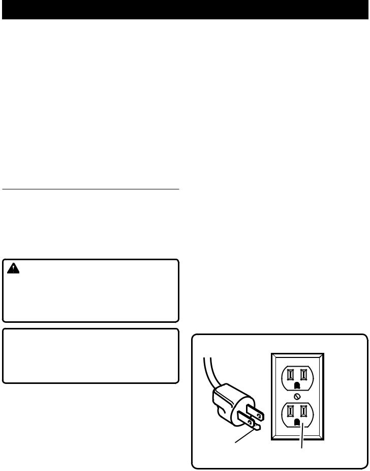
Grounding Instructions
In the event of a malfunction or breakdown, grounding provides a path of least resistance for electric current to reduce the risk of electric shock. This tool is equipped with an electric cord having an equipment-grounding conductor and a grounding plug. The plug must be plugged into a matching outlet that is properly installed and grounded in accordance with all local codes and ordinances.
Do not modify the plug provided. If it will not fit the outlet, have the proper outlet installed by a qualified electrician. Improper connection of the equipment-grounding conductor can result in a risk of electric shock. The conductor with insulation having an outer surface that is green with or without yellow stripes is the equipment-grounding conductor. If repair or replacement of the electric cord or plug is necessary, do not connect the equipment-grounding conductor to a live terminal.
Check with a qualified electrician or service personnel if the grounding instructions are not completely understood, or if in doubt as to whether the tool is properly grounded.
Repair or replace a damaged or worn cord immediately.
This tool is intended for use on a circuit that has an outlet like the one shown in figure 1. It also has a grounding pin like the one shown.
Grounding |
120V Grounded outlet |
Pin |
Fig. 1
 Loading...