


I N S T A L L A T I O N / O P E R A T I O N M A N U A L
LS-3 Series
LS-5 Series
Home Theater Projectors
LS-3
LS-3/CineWide™
LS-5
LS-5/CineWide™

RuncoCare™ Standard Two Year Limited
Warranty
Congratulations on your purchase of a Runco® product! With proper installation, setup and care, you should enjoy many years of unparalleled video performance.
This RuncoCare Standard Limited Warranty is provided free of charge by Runco International with the purchase of a covered Runco product. The following sets forth Runco’s Standard Limited Warranty applicable to all Runco projectors, processors, LCD and plasma display products, with the exception of the following models: XP-103DHD, SC-1, SC-1a and VW-100HD1.
The following terms and conditions of the RuncoCare Standard Limited Warranty represent a contract between us, Runco International and you, the customer who has purchased a Runco product. This contract applies to purchases of covered Runco products occurring on or after September 1, 2008. Runco reserves the right to change the terms of this contract, and such changes shall apply to purchases of covered Runco products that occur on or after any future effective date.
RuncoCare Standard Features
•Two-year protection from defects in material and workmanship
•Access to 24x7 phone support
•Complimentary, second-day one-way shipping
Warranty Coverage
Runco warrants its products to be free from defects in material and workmanship during the warranty period provided below. If, in Runco’s determination, a product proves to be defective in material or workmanship during the warranty period, Runco will repair the product, replace the product with a similar new or like new product, or refund a prorata share of the purchase price (calculated based on the remainder of the warranty period and the thencurrent MSRP2 of a similar product), if repair or replacement of the product is determined by Runco to not be feasible.
Length of Warranty
Runco products are warranted for two (2) years from the date of shipment from Runco. Lamps are warranted six (6) months from the date of shipment or 1000 hours, whichever comes first. All other accessories, which includes, but is not limited to, cables, remotes, carrying cases, lens cap and other peripherals sold with the Runco product, are warranted for ninety (90) days from the date of shipment. Repaired product or replacement lamp is subsequently warranted for the remaining portion (if any) of the original warranty term or 90 days from the date the product was shipped to you, whichever is longer.
Eligibility
This RuncoCare Standard Limited Warranty is valid only for the first customer who purchases the covered product from an authorized Runco dealer or distributor. This warranty is not transferable. You may be required to provide proof of purchase in order to receive warranty services.
1.Runco may update this list of products excluded from this warranty from time to time at Runco’s sole discretion, but updates to the list of covered products will not apply on a retroactive basis.
2.MSRP is defined as the most recent product price listed on Runco’s price list.
Runco LS-3/LS-5 Installation/Operation Manual |
iii |

RuncoCare Claim Procedure
In the event of a product defect, please follow the warranty claim procedure provided below:
1.The Customer is required to contact a Runco dealer or Runco Technical Support via email at support@runco.com or via phone at (toll free) 800-23RUNCO (800-237-8626). If the customer is located outside North America, call +3589 4200 554 in Europe for product service.
2.Be prepared to provide the date of purchase, the place of purchase, serial number, product model number, description of the problem and troubleshooting steps already attempted.
3.Runco Technical Support staff will attempt to correct any minor issues that may be causing the problem. If Runco is unable to fix the problem to the customer’s satisfaction, Runco will issue a Return Material Authorization (RMA) if it is determined that the claim was made within the coverage period of the Standard Limited Warranty.
4.The customer will need to return the defective product to the Runco repair depot location specified by the Runco technical support representative. The customer will need to properly package the defective product, consisting of the product only, and not include any accessories (e.g., cables, remotes, carrying cases, lens, lens cap and other peripherals) and return it to the Runco repair depot specified by the technical support representative. It is the customer’s responsibility to properly package the hardware, include all appropriate materials, and return it to the location specified by the Runco technical support department. The customer will need to address and resolve any shipping damage claims directly with the shipping company.
5.The customer is responsible for providing a suitable box to ship the defective product to an authorized Runco repair depot. Boxes may be purchased from a Runco technical support representative.
6.The customer is responsible for paying freight charges to ship the defective product to an authorized Runco repair depot.
7.Runco will pay freight charges to return the repaired/replacement product to the customer from the Runco repair depot.
8.Once an RMA has been created, the customer may contact serviceorders@runco.com for followup questions or confirmation status of the claim process.
Warranty Exclusions
This RuncoCare Standard Limited Warranty does not include or is limited by the following:
1.Products not purchased from an authorized Runco dealer
2.Rental costs incurred by the customer in the event of product defect or failure
3.Any product with a defaced, modified, or removed serial number
4.Damage, deterioration, or malfunction resulting from:
a Accident, abuse, misuse, neglect, improper ventilation, fire, water, disaster, lightning, or other acts of nature, smoke exposure (cigarette or otherwise), unauthorized product modification (including use of an unauthorized mount), or failure to follow instructions supplied with the product
b Repair or attempted repair by anyone not authorized by Runco c Any damage to the product due to shipment
d Removal or installation of the product
e Causes external to the product, such as electric power fluctuations or failure f Use of supplies or parts not meeting Runco’s specifications
g Normal wear and tear
h Expected lamp degradation and normal decrease in lamp output over a period of time or as the lamp is consumed i Customer caused defects, including but not limited to, scratched/defaced/altered plastics
iv |
Runco LS-3/LS-5 Installation/Operation Manual |

jFailure to follow maintenance procedures as outlined in the product’s user guide where a schedule is specified for regular cleaning of the product
kOpening the product and/or tampering with internal circuitry
lProducts lost, stolen or discarded
mAny damage or dissatisfaction associated with latent images, “burnin,” or any other damage determined by Runco to be the result of customer use patterns
nAny other cause, which does not relate to a product defect in material or workmanship
5.Removal, installation, and setup service charges are excluded from this Standard Limited warranty
6.Runco’s warranty does not cover black uniformity issues or other LCD issues associated with usage outside the Runco recommended guidelines and specifications for the product
7.Second day shipment delivery time and availability may vary based on origin and destination and Runco is unable to deliver to PO Box and FPO Box addresses
Extended Service Options
Runco offers extended and expanded service plans. For information on additional product protection, please email serviceorders@runco.com or call (toll free) 800-23RUNCO (800-237-8626).
Online Product Registration
Please visit http://www.runco.com/info.html to register product.
Limitation of Implied Warranties
RUNCO PROVIDES NO WARRANTIES, EXPRESS OR IMPLIED, EXCEPT THOSE EXPRESSLY PROVIDED HEREIN. RUNCO EXPRESSLY DISCLAIMS ALL OTHER WARRANTIES, INCLUDING THE IMPLIED WARRANTIES OF MERCHANTABILITY AND FITNESS FOR A PARTICULAR PURPOSE.
Runco LS-3/LS-5 Installation/Operation Manual |
v |

Exclusion of Damages
RUNCO’S MAXIMUM AGGREGATE LIABILITY HEREUNDER IS LIMITED TO THE COST OF REPAIR OR REPLACEMENT OF THE PRODUCT.
1.RUNCO SHALL NOT BE LIABLE FOR DAMAGE TO OTHER PROPERTY CAUSED BY ANY DEFECT IN THE PRODUCT, DAMAGES BASED UPON INCONVENIENCE, LOSS OF USE OF THE PRODUCT, LOSS OF TIME, LOSS OF PROFITS, LOSS OF BUSINESS OPPORTUNITY, LOSS OF GOODWILL, INTERFERENCE WITH BUSINESS RELATIONSHIPS, OR OTHER COMMERCIAL LOSS, EVEN IF THE CUSTOMER HAS BEEN ADVISED OF THE POSSIBILITY OF SUCH DAMAGES.
2.RUNCO SHALL NOT BE LIABLE FOR ANY CONSEQUENTIAL, INCIDENTAL, INDIRECT, SPECIAL, OR PUNITIVE DAMAGES ANY OTHER DAMAGES, WHETHER INCIDENTAL, INDIRECT, CONSEQUENTIAL OR OTHERWISE.
3.RUNCO SHALL NOT BE LIABLE FOR ANY CLAIM AGAINST THE CUSTOMER BY ANY OTHER PARTY.
Effect of Local Law
This warranty gives you specific legal rights, and you may have other rights, which vary from locality to locality. Some localities do not allow limitations on implied warranties and/or do not allow the exclusion of incidental or consequential damages, so the above limitations and exclusions may not apply to you.
COPYRIGHT AND TRADEMARKS:
© Copyright 2009 Runco International, LLC (“Runco”). This document contains proprietary information protected by copyright, trademark and other intellectual property laws. All rights are reserved. No part of this manual may be reproduced by any mechanical, electronic or other means, in any form, without prior written permission of Runco.
The trademarks reporduced in this Runco Owner’s Manual and used on the Runco Products are either owned by Runco or are licensed by Runco. You may not reproduce or use the trademarks without the prior written consent of Runco.
Runco Products are manufactured under one or more of the following patents: US. Patent 6755540 and Other Patents Pending.
vi |
Runco LS-3/LS-5 Installation/Operation Manual |
Important Safety Instructions
Thank you for your purchase of this quality Runco video product! For the best performance, please read this manual carefully as it is your guide through the menus and operation.
CAUTION
RISK OF ELECTRIC SHOCK
DO NOT OPEN
CAUTION:
TO REDUCE THE RISK OF ELECTRIC SHOCK DO NOT REMOVE COVER (OR BACK)
NO USER SERVICEABLE PARTS INSIDE. REFER SERVICING TO QUALIFIED SERVICE PERSONNEL.
WARNING
This symbol is intended to alert the user to the presence of uninsulated “dangerous voltage” within the product’s enclosure that may be of sufficient magnitude to constitute a risk of electric shock.
This symbol is intended to alert the user to the presence of important operating and maintenance (servicing) instructions in the literature accompanying the appliance.
1.Read these instructions.
2.Keep these instructions.
3.Heed all warnings.
4.Follow all instructions.
5.Do not use this apparatus near water.
6.Clean only with a dry cloth.
7.Do not block any of the ventilation openings. Install in accordance with the manufacturer’s instructions.
8.Do not install near any heat sources such as radiators, heat registers, stoves, or other apparatus (including amplifiers) that produce heat.
9.Do not defeat the safety purpose of the polarized or grounding type plug. A polarized plug has two blades with one wider than the other. A grounding type plug has two blades and a third grounding prong. The wide blade or the third prong is provided for your safety. When the provided plug does not fit into your outlet, consult an electrician for the replacement of the obsolete outlet.
10.Protect the power cord from being walked on or pinched particularly at plugs, convenience receptacles and the point where they exit from the apparatus.
11.Only use the attachments/accessories specified by the manufacturer.
12.Use only with a cart, stand, tripod, bracket or table specified by the manufacturer or sold with the apparatus. When a cart is used, use caution when moving the cart/apparatus to avoid injury from tip-over.
13.Unplug this apparatus during lightning storms or when unused for long periods of time.
14.Refer all servicing to qualified service personnel. Servicing is required when the apparatus has been damaged in
any way, such as power supply cord or plug is damaged, liquid has been spilled or objects have fallen into the apparatus, the apparatus has been exposed to rain or moisture, does not operate normally, or has been dropped.
15.The +12V trigger only outputs 12Vdc signal for triggering. Do not connect to any other power input or output. This could cause damage to this unit.
16.Keep the packing material in case the equipment should ever need to be shipped.
17.The lamp becomes extremely hot during operation. Allow the projector to cool down for approximately 45 minutes prior to removing the lamp assembly for replacement.
18.Do not operate lamps beyond the rated lamp life. Excessive operation of lamps beyond rated life could cause them to explode in rare occasions.
Runco LS-3/LS-5 Installation/Operation Manual |
vii |

19. Never look directly into the lens when the lamp is on.
Compliance Information
DECLARATION OF CONFORMITY:
Manufacturer’s Name: Runco International, LLC
Manufacturer’s Address: 1195 NW Compton Drive, Beaverton, OR 97006-1992 hereby declares that the Products’ Model Numbers:
LS-3, LS-3/CineWide, LS-5 and LS-5/CineWide conform with the provisions of:
Council Directive 2004/108/EC on Electromagnetic Compatibility;
EN 55022 “Limits and methods of measurements of radio interference characteristics of information technology equipment” 1998;
EN 55024 “Limits and methods of measurements of immunity characteristics of information technology equipment” 1998; Including:
•EN 61000-4-2 “Electromagnetic compatibility (EMC) Part 4: Testing and measurement techniques Section 2: Electrostatic discharge immunity test”
•EN 61000-4-3 “Electromagnetic compatibility (EMC) Part 4: Testing and measurement techniques Section 3: Radiated, Radio-Frequency, Electromagnetic Field Immunity Test”
•EN 61000-4-4 “Electromagnetic compatibility (EMC) Part 4: Testing and measurement techniques Section 4: Electrical fast transient/burst immunity test”
•EN 61000-4-5 "Electromagnetic compatibility (EMC) Part 4: Testing and measurement techniques Section 5: Surge immunity test"
•EN 61000-4-6 "Electromagnetic compatibility (EMC) Part 4: Testing and measurement techniques Section 6: Conducted disturbances induced by radio-frequency fields immunity test"
•EN 61000-4-8 "Electromagnetic compatibility (EMC) Part 4: Testing and measurement techniques Section 8: Conducted disturbances induced by power frequency magnetic fields immunity test"
•EN 61000-4-11 "Electromagnetic compatibility (EMC) Part 4: Testing and measurement techniques Section 11: Voltage dips, short interruptions and voltage variations immunity tests"
And:
•EN 61000-3-2 "Electromagnetic compatibility (EMC) Part 3, Section 2: Limits for harmonic current emissions (equipment input current up to and including 16 A per phase)" 2000;
•EN 61000-3-3 "Electromagnetic compatibility (EMC) Part 3, Section 3: Limitations of voltage changes, voltage fluctuations and flicker in public low-voltage supply systems, for equipment with rated current up to and including 16 A and not subject to conditional connection" 1995;
Council Directive 2006/95/EC and amended by M1 and C1 on Low Voltage Equipment Safety;
EN 60950 “Safety of information technology equipment, including electrical business equipment”
The Technical Construction file required by this Directive is maintained at the corporate headquarters of Runco International, LLC, located at 1195 NW Compton Drive, Beaverton, OR 97006-1992.
Date of Declaration: November 2009
viii |
Runco LS-3/LS-5 Installation/Operation Manual |
FCC PART 15:
NOTE: This equipment has been tested and found to comply with the limits for a Class B digital device, pursuant to Part 15 of the FCC Rules. These limits are designed to provide reasonable protection against harmful interference in a residential installation.
This equipment generates, uses and can radiate radio frequency energy and, if not installed and used in accordance with the instructions, may cause harmful interference to radio communications. However, there is no guarantee that interference will not occur in a particular installation. If this equipment does cause harmful interference to radio or television reception, which can be determined by turning the equipment off and on, the user is encouraged to try to correct the interference by one or more of the following measures:
•Reorient or relocate the receiving antenna.
•Increase the separation between the equipment and receiver.
•Connect the equipment into an outlet on a circuit different from that to which the receiver is connected.
•Consult the dealer or an experienced radio/TV technician for help.
INDUSTRY CANADA (ICES-003):
This Class B digital apparatus complies with Canadian ICES-003.
Cet appareil numérique de la classe B est conforme à la norme NMB-003 du Canada.
PRODUCT DISPOSAL:
The Product contains small amounts of tin, lead and/or mercury. Disposal of these materials may be regulated due to environmental considerations.
IMPORTANT RECYCLE INSTRUCTIONS
Lamp(s) inside this product contain mercury. This product may contain other electronic waste that can be hazardous if not disposed of properly. Recycle or dispose in accordance with local, state, or federal Laws.
For more information, contact the Electronic Industries Alliance at WWW.EIAE.ORG.
For lamp specific disposal information check WWW.LAMPRECYCLE.ORG.
DISPOSAL OF OLD ELECTRICAL AND ELECTRONIC EQUIPMENT (Applicable throughout the European Union and other European countries with separate collection programs)
This symbol found on your product or on its packaging, indicates that this product should not be treated as household waste when you wish to dispose of it. Instead, it should be handed over to an applicable collection point for the recycling of electrical and electronic equipment. By ensuring this product is disposed of correctly, you will help prevent potential negative consequences to the environment and human health, which could otherwise be caused by inappropriate disposal of this product. The recycling of materials will help to conserve natural resources. This symbol is only valid in the European Union. If you wish to discard this product, please contact your local authorities or dealer and ask for the correct method of disposal.
Runco LS-3/LS-5 Installation/Operation Manual |
ix |

Notes:
x |
Runco LS-3/LS-5 Installation/Operation Manual |
|
Table of Contents |
|
RuncoCare™ Standard Two Year Limited Warranty |
................................................... iii |
|
Important Safety Instructions ....................................................................................... |
vii |
|
Compliance Information .............................................................................................. |
viii |
|
1. |
Introduction ............................................................................................................... |
1 |
|
About This Manual ....................................................................................................... |
1 |
|
Target Audience ..................................................................................................... |
1 |
|
If You Have Comments About This Manual............................................................. |
1 |
|
Textual and Graphic Conventions ........................................................................... |
1 |
|
Using This Manual ........................................................................................................ |
2 |
|
Description, Features and Benefits ............................................................................... |
3 |
|
Key Features and Benefits ...................................................................................... |
4 |
|
Parts List ................................................................................................................ |
4 |
2. |
Controls and Functions ............................................................................................ |
5 |
|
LS-3/LS-5 at a Glance ................................................................................................. |
5 |
|
LS-3/LS-5 Rear Panel .................................................................................................. |
9 |
|
LS-3/LS-5 Remote Control ........................................................................................ |
11 |
3. |
Installation ............................................................................................................... |
13 |
|
Remote Control .......................................................................................................... |
13 |
|
Notes on Batteries ................................................................................................ |
13 |
|
Notes on Remote Control Operation..................................................................... |
13 |
|
Quick Setup ............................................................................................................... |
15 |
|
Installation Considerations .......................................................................................... |
16 |
|
Installation Type .................................................................................................... |
16 |
|
Ambient Light ....................................................................................................... |
17 |
|
Throw Distance..................................................................................................... |
17 |
|
Vertical and Horizontal Position............................................................................. |
18 |
|
Lens Shift ............................................................................................................. |
19 |
|
Folded Optics ....................................................................................................... |
21 |
|
Other Considerations ............................................................................................ |
21 |
|
Installing the Optional CineWide Lens Mount .............................................................. |
21 |
|
Installing the Fixed CineWide Base Plate............................................................... |
22 |
Runco LS-3/LS-5 Installation/Operation Manual |
xi |

Table of Contents
|
Mounting the LS-3/LS-5 ............................................................................................. |
23 |
|
Floor Mounting (Upright) ....................................................................................... |
23 |
|
Ceiling Mounting (Inverted).................................................................................... |
23 |
|
Adjusting the Projection Angle .............................................................................. |
23 |
|
Connections to the LS-3/LS-5 .................................................................................... |
24 |
|
Connector Panel Access....................................................................................... |
24 |
|
Connecting Source Components to the LS-3/LS-5............................................... |
25 |
|
RS-232 Controller Connection .............................................................................. |
29 |
|
Connecting 12-Volt Trigger Output to External Theater Equipment ....................... |
30 |
|
Connecting an External IR Receiver ...................................................................... |
30 |
|
Connecting to AC Power ...................................................................................... |
31 |
|
Turning on the Power ................................................................................................. |
31 |
|
Lens Adjustments ...................................................................................................... |
31 |
|
Focus and Zoom .................................................................................................. |
31 |
|
Lens Shift ............................................................................................................. |
31 |
|
Changing the OSD Language ..................................................................................... |
33 |
|
Adjusting the Picture Orientation ................................................................................ |
33 |
|
Rear Projection ..................................................................................................... |
33 |
|
Ceiling Mode......................................................................................................... |
33 |
|
Installing and Adjusting the CineWide Anamorphic Lens ............................................. |
34 |
4. |
Operation ................................................................................................................. |
37 |
|
Selecting Video Memory ............................................................................................. |
37 |
|
Selecting an Aspect Ratio .......................................................................................... |
37 |
|
Selecting An Input Source .......................................................................................... |
37 |
|
Using Picture-In-Picture (PIP) ..................................................................................... |
38 |
|
Using the On-Screen Menus ...................................................................................... |
39 |
|
Main ..................................................................................................................... |
41 |
|
Advanced ............................................................................................................. |
51 |
|
System ................................................................................................................. |
57 |
|
Control ................................................................................................................. |
61 |
|
Language ............................................................................................................. |
63 |
|
Service ................................................................................................................. |
64 |
5. |
Maintenance and Troubleshooting ........................................................................ |
67 |
|
Lamp Replacement .................................................................................................... |
67 |
|
Troubleshooting Tips .................................................................................................. |
68 |
xii |
Runco LS-3/LS-5 Installation/Operation Manual |

|
|
Table of Contents |
6. |
Serial Communications .......................................................................................... |
71 |
|
RS-232 Connection and Port Configuration ............................................................... |
71 |
|
Serial Command Syntax ............................................................................................. |
71 |
|
Key Commands.................................................................................................... |
71 |
|
Operations Commands......................................................................................... |
74 |
|
RS-232 Error Codes ............................................................................................. |
82 |
7. |
Specifications .......................................................................................................... |
83 |
|
LS-3/LS-5 Specifications ............................................................................................ |
83 |
|
LS-3/LS-5 Dimensions ............................................................................................... |
86 |
|
Supported Timings ..................................................................................................... |
87 |
Runco LS-3/LS-5 Installation/Operation Manual |
xiii |

Table of Contents
Notes:
xiv |
Runco LS-3/LS-5 Installation/Operation Manual |

List of Figures |
|
2-1. LS-3/LS-5 Front/Side View........................................................................................... |
5 |
2-2. LS-3/LS-5 Rear/Bottom/Top View................................................................................ |
7 |
2-3. LS-3/LS-5 Rear Panel .................................................................................................. |
9 |
3-1. IR Reception Angles ................................................................................................... |
14 |
3-2. Estimating Throw Distance ......................................................................................... |
17 |
3-3. Projector Placement ................................................................................................... |
18 |
3-4. Vertical Lens Shift (Example Only)............................................................................... |
19 |
3-5. Horizontal Lens Shift (Example Only)........................................................................... |
20 |
3-6. Folded Optics............................................................................................................. |
21 |
3-7. Projector with Whitney (Prismatic) Lens Base Plate - Bottom View ............................. |
22 |
3-8. HDMI/DVI Source Connections .................................................................................. |
25 |
3-9. RGB Connections ...................................................................................................... |
26 |
3-10. Component Video Connections................................................................................ |
27 |
3-11. Composite and S-Video Connections....................................................................... |
28 |
3-12. RS-232 Control System Connection......................................................................... |
29 |
3-13. 12-Volt Trigger Output Connection........................................................................... |
30 |
3-14. External IR Receiver Connection............................................................................... |
30 |
3-15. Anamorphic Lens Mounting Assembly - Exploded View ........................................... |
34 |
4-1. LS-3/LS-5 OSD Menu Structure................................................................................. |
40 |
4-2. LS-3/LS-5 Main Menu ................................................................................................ |
41 |
4-3. Typical PLUGE Pattern for Adjusting Brightness ......................................................... |
46 |
4-4. Typical Gray Bar Pattern for Adjusting Contrast .......................................................... |
46 |
4-5. Typical Test Pattern for Adjusting Sharpness.............................................................. |
47 |
4-6. Overscan Examples.................................................................................................... |
49 |
4-7. Source Select Sub-Menu ........................................................................................... |
50 |
4-8. LS-3/LS-5 Advanced Menu........................................................................................ |
51 |
4-9. RGB Adjust Sub-Menu............................................................................................... |
54 |
4-10. Fine Sync Sub-Menu ................................................................................................ |
55 |
4-11. LS-3/LS-5 System Menu.......................................................................................... |
57 |
4-12. Source Enable Sub-Menu ........................................................................................ |
58 |
4-13. PIP and PBP areas for 1080p Display....................................................................... |
59 |
4-14. PIP Split-Screen Mode ............................................................................................. |
60 |
4-15. LS-3/LS-5 Service Menu .......................................................................................... |
64 |
7-1. LS-3/LS-5 Dimensions ............................................................................................... |
86 |
Runco LS-3/LS-5 Installation/Operation Manual |
xv |

List of Figures
Notes:
xvi |
Runco LS-3/LS-5 Installation/Operation Manual |
Introduction
1. Introduction
This Owner’s Manual describes how to install, set up and operate the Runco LS-3/LS-5 Digital Light Processing (DLP™) Projector.
Throughout this manual, the Runco LightStyle™ Series LS-3/LS-5 Home Theater Projector is referred to as the “LS-3/LS-5.”
1.1
About This Manual
Runco has prepared this manual to help home theater installers and end users get the |
Target Audience |
most out of the LS-3/LS-5. |
|
Runco has made every effort to ensure that this manual is accurate as of the date it was |
|
printed. However, because of ongoing product improvements and customer feedback, it |
|
may require updating from time to time. You can always find the latest version of this and |
|
other Runco product manuals on-line, at www.Runco.com. |
|
Runco welcomes your comments about this manual. Send them to info@Runco.com. |
If You Have Comments |
|
About This Manual... |
Text Conventions: The following conventions are used in this manual, in order to clarify |
Textual and Graphic |
the information and instructions provided: |
Conventions |
• Remote and built-in keypad button identifiers are set in upper-case bold type; for |
|
example, “Press EXIT to return to the previous menu.” |
|
• Computer input (commands you type) and output (responses that appear on-screen) is |
|
shown in monospace (fixed-width) type; for example: “To change the aspect ratio to |
|
Letterbox, type op aspect = 1 <Enter>. ” |
|
• All keys with functional names are initial-capped, set in bold type and enclosed in angle |
|
brackets. These keys are the following: <Enter>, <Spacebar>, <Control>, |
|
<Esc> and <Tab>. |
|
• <Enter> indicates that you may press either the RETURN or ENTER key on your |
|
keyboard if it has both keys. |
|
In addition to these conventions, underlining, boldface and/or italics are occasionally used |
|
to highlight important information, as in this example: |
|
A carriage return must be used after each command or string. |
|
Note |
|
Runco LS-3/LS-5 Installation/Operation Manual |
1 |
Introduction
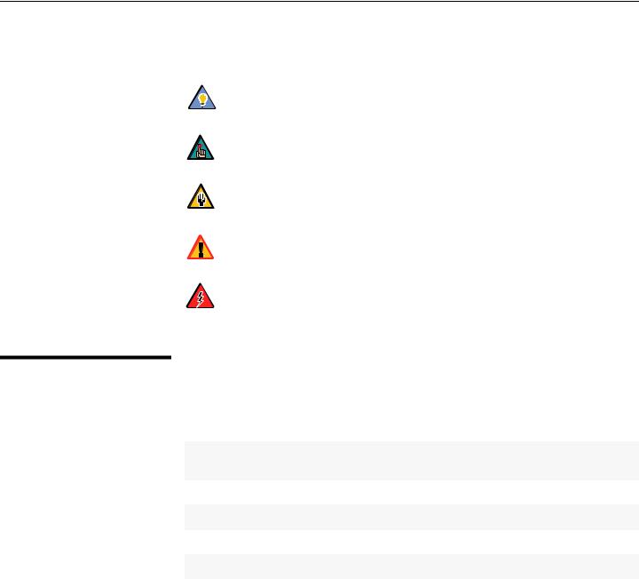
Graphic Conventions: These symbols appear in numerous places throughout the manual, to emphasize points that you must keep in mind to avoid problems with your equipment or injury:
Tip |
TIPS highlight time-saving short cuts and helpful guidelines for using |
|
certain features. |
||
Note |
NOTES emphasize text with unusual importance or special |
|
significance. They also provide supplemental information. |
||
Caution |
CAUTIONS alert users that a given action or omitted action can |
|
degrade performance or cause a malfunction. |
||
|
||
WARNING |
WARNINGS appear when a given action or omitted action can result |
|
in damage to the equipment, or possible non-fatal injury to the user. |
||
DANGER! |
DANGER appears when a given action can cause severe injury or |
|
death. |
||
|
1.2
Using This Manual
Use the following table to locate the specific information you need in this manual.
If you need... |
... Turn to page: |
|
|
Information about obtaining service |
iv |
General information about the LightStyle™ Series LS-3/LS-5 |
3 |
Home Theater Projector |
|
Installation instructions |
13 |
First-time configuration instructions |
31 |
Advanced configuration instructions |
51 |
Troubleshooting tips |
68 |
Specifications for the LightStyle™ Series LS-3/LS-5 Home The- |
83 |
ater Projector |
|
|
|
2 |
Runco LS-3/LS-5 Installation/Operation Manual |

Introduction
Elegant and electrifying, the LightStyle™ Series LS-3/LS-5 Home Theater Projector is Runco’s first-ever 1080p projector designed for both performance and esthetics. Where sleek design encompasses incredible performance, this stylish combination of legendary Runco engineering and impactful design yield a powerhouse that elevates the bar for affordable home theater projection.
Designed inside and out by Runco’s award-winning engineering and design team, the LS-3/LS-5 incorporates Runco’s proprietary engineering, advanced features and performance enhancements to achieve an elevated home theater experience. Combining a 1080p native resolution DLP™ light engine featuring Runco’s powerful SuperOnyx™ technology with ConstantContrast™ for bright, pristine, high-definition images with deep black levels and significant contrast, the LS-3/LS-5 projects pristine images from any source.
The LS-3/LS-5 is equipped with a precision optics package offering zoom, focus and lens shift controls and a throw range of 1.85:1 to 2.40:1. For installations requiring shorter throw distances, the LS-3/LS-5 is optionally available with a lens that offers a throw range of 1.56:1 to 1.86:1.
To ensure a perfect fit in any room at any time, the LS-3/LS-5 incorporates the ISF™ (Imaging Science Foundation) calibration suite for optimal performance in various rooms and lighting conditions. These calibration tools feature day and night calibration memory settings, individual sharpness and noise reduction controls, programmable image memory selection keys, built-in test patterns and a dark room-optimized remote.
Runco’s advanced ViVix™ digital video processing enhances the LS-3/LS-5 picture quality and provide artifact-free scaling. Rounding out this impressive projector are discrete input source, aspect ratio and power on/off, as well as an RS-232 interface for seamless integration with automation control systems.
For uncompromised widescreen reproduction of movies originally filmed in the CinemaScope™ 2:35:1 format, the LS-3/LS-5 can also be paired with Runco’s award-winning CineWide™ technology. Through an ingenious combination of software, electronics and precision anamorphic optics, CineWide maintains constant image height on the screen just as in a movie theater. When a viewer transitions from 1.78:1 (16:9) program material to superwide 2.35:1, the image simply gets wider while image height is maintained.
With Runco CineWide, the projection system is able to use the full pixel array, thereby producing a 2.35:1 image with enhanced resolution and increased brightness. No resolution or image area is lost to those black bars that contain no picture information.
Note |
CineWide requires the use of a 2.35:1 or similar aspect ratio superwide |
format screen. |
1.3
Description, Features and Benefits
Runco LS-3/LS-5 Installation/Operation Manual |
3 |

Introduction
Key Features and Benefits The LS-3/LS-5 offers these key features and benefits:
•Native Resolution: 1920 x 1080 (16:9 Native Aspect Ratio)
•DLP system using high-performance Digital Micromirror Device (DMD)
•Customized color wheel produces wide dynamic range and rich grayscale
•ConstantContrast™ provides for infinitely variable adjustment of the light path through the optics, enabling the perfect balance of black and white levels for any type of video source material
•Picture in Picture function allows you to display two inputs on the screen at the same time
•Two (2), HDMI 1.3 Inputs with High-bandwidth Digital Content Protection (HDCP)
•HDTV Compatible
Additional Features of the LS-5:
•Greater optical contrast (up to 15,000:1 with ConstantContrast enabled)
•Horizontal (as well as vertical) lens shift
•Expanded connectivity (additional component video input and 12-volt trigger output)
Parts List Your LS-3/LS-5 is shipped with the following items. If any items are missing or damaged, please contact your Runco dealer or Runco Customer Service at (800) 23RUNCO.
•LS-3/LS-5 DLP Projector
•Remote Control Unit and two (2), AA-size batteries
•AC Power Cords (North America, Europe, United Kingdom)
•Source Connection Cables:
•Component Video
•HDMI to HDMI
•Warranty information and registration card
•Cleaning Cloth
•5.0-mm Hex wrench (for lens shift adjustment)
•Runco LS-3/LS-5 Installation/Operation Manual (this document)
•Runco LS-3/LS-5 Quick Setup Guide
Optional Accessories:
•CineWide™ technology (fixed, secondary anamorphic lens)
•Ceiling mount kit (part number 997-4214-00)
•Short-throw lens, 1.56:1-1.86:1
•Replacement Lamp (part number 997-5268-00)
4 |
Runco LS-3/LS-5 Installation/Operation Manual |
Controls and Functions
2. Controls and Functions
Figure 2-1 and Figure 2-2 show the key LS-3/LS-5 components.
2.1
LS-3/LS-5 at a Glance
Top IR Sensor
System 
Keypad
Power Button/
Status LED
Exhaust Vent (on side)
Intake |
Focus Ring |
|
Projection Lens |
||
Vent |
Front 
IR Sensor
Zoom Ring
Figure 2-1. LS-3/LS-5 Front/Side View
•TOP IR SENSOR
Receives infrared signals from the remote control unit.
•POWER BUTTON/STATUS LED
Indicates projector status as follows:
•Solid green = AC power present, ready to turn on (lamp not lit)
•Flashing green = lamp is warming up or cooling down; keypad functions not allowed
•Off = Lamp lit, projector functioning normally
•Alternating green/red = Lamp problem (door open, unable to strike, end of life), user intervention likely to fix problem
•Flashing red = Over temperature, user intervention (clear vents, turn on AC) may fix problem
•Solid red = Error that requires servicing (fan fail, Power-on self-test fail etc.)
•EXHAUST VENT
Warm air exits the projector through this vent. Ensure that it is not blocked.
•FOCUS RING
Rotate this to focus the projected image.
•PROJECTION LENS
Available in two versions: standard throw range (1.85:1 to 2.40:1) and short throw range (1.56:1 to 1.86:1).
Runco LS-3/LS-5 Installation/Operation Manual |
5 |
Controls and Functions
|
• |
ZOOM RING |
||
|
|
Rotate this to change the projected image size. |
||
|
• |
FRONT IR SENSOR |
||
|
|
Receives infrared signals from the remote control unit. |
||
|
• |
INTAKE VENT |
||
|
|
Internal fans draw cool air into the projector through this vent. |
||
|
• |
SYSTEM KEYPAD |
||
|
SOURCE |
Provides an alternative to using the remote control unit to select a source or navigate |
||
|
the on-screen display (OSD) controls. |
|||
|
▲ |
SOURCE |
||
|
|
Use this button to select a video source. |
||
◄ |
► |
Cursor Keys ( , , , ) |
||
|
|
Use these buttons to select items or settings, adjust settings or switch display patterns. |
||
|
▲ |
ENTER |
( ) |
|
|
|
Press to |
select |
a highlighted menu item or confirm a changed setting. |
|
MENU |
MENU |
||
|
|
Press this button to show or hide the OSD menus. |
||
6 |
Runco LS-3/LS-5 Installation/Operation Manual |
Controls and Functions
1 
 2
2
3 
 4
4
5
7  6
6
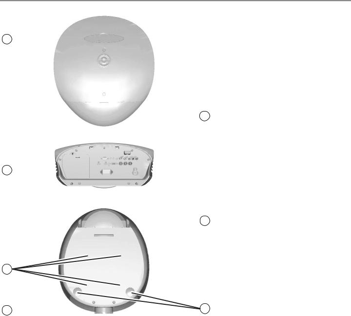
Figure 2-2. LS-3/LS-5 Rear/Bottom/Top View
Runco LS-3/LS-5 Installation/Operation Manual |
7 |
Controls and Functions
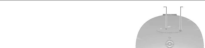
1. RUNCO LOGO BADGE |
Vertical Lens Shift |
Horizontal |
Remove to access the lens shift |
|
Lens Shift |
controls. |
|
(LS-5 only) |
2.REAR COVER
Remove to access connectors.
3.LAMP MODULE COVER
Remove this cover to access the lamp compartment.
4.CABLE OPENING
Pass cables through this opening.
5.CEILING MOUNT HOLES
Use these to attach the ceiling bracket to the projector. Use M4 screws with a maximum screw depth of 10 mm (0.39 inch).
6.ADJUSTABLE FEET
Use these when the projector is installed in a table-top configuration to level the image and/or adjust the projection angle.
7.PROJECTION LENS
The inside of the lens barrel is threaded to accommodate a standard, 72-mm lens filter. For example, with a smaller screen you can install a neutral-density filter to reduce the overall light output.
8 |
Runco LS-3/LS-5 Installation/Operation Manual |

Controls and Functions
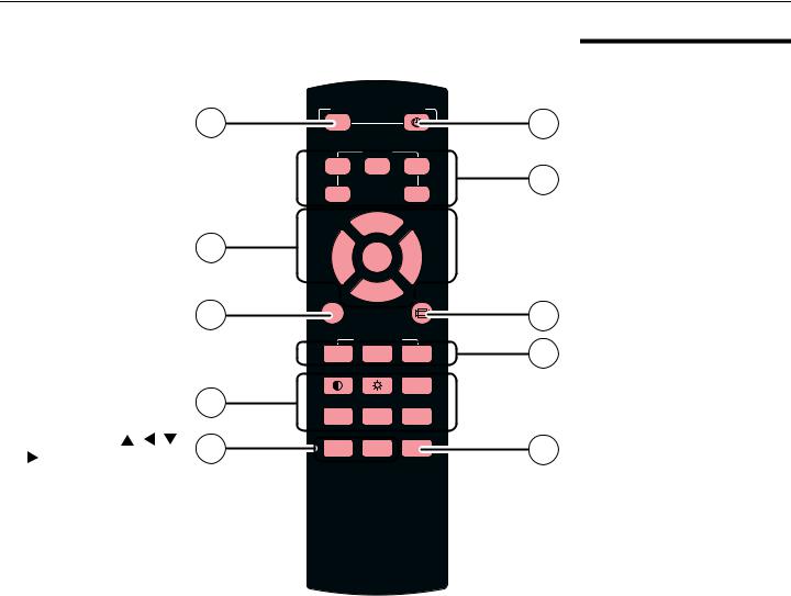
1.ON
Use this button to turn
|
the projector on. |
1 |
ON |
POWER |
OFF |
2 |
|
l |
|
|
|||
2. |
OFF |
|
|
|
||
|
|
SOURCE |
|
|
||
|
Use this button to turn |
|
|
|
|
|
|
|
1 |
2 |
3 |
3 |
|
|
the projector off. |
|
4 |
|
5 |
|
3. |
Source Selection |
|
|
|
||
|
|
|
|
|
||
|
Buttons (1-5): |
|
|
▲ |
|
|
|
Press to select a video |
4 |
▲ |
ENTER |
▼ |
|
|
source. By default, these |
|
|
|
|
|
|
buttons are assigned as |
|
|
▼ |
|
|
|
follows: 1 = HDMI 1; 2 = |
6 |
MENU |
|
|
5 |
|
HDMI 2; 3 = |
|
|
|
||
|
Component 1; 4 = |
|
|
USER MEMORY |
|
7 |
|
|
M1 |
M2 |
M3 |
||
|
S-Video; 5 = Video. |
|
||||
|
|
|
|
|
||
|
However, you can assign |
|
|
|
SHARP |
|
|
each button to any |
8 |
|
|
|
|
|
|
|
|
|
||
|
source you wish. |
GAMMA |
OS |
NR |
|
|
|
|
|
||||
4. |
Cursor Keys ( , , , |
10 |
PIP |
SWAP |
LIGHT |
9 |
|
) |
|||||
|
|
|
|
Use these buttons to select items or settings, adjust settings or switch display patterns.
ENTER
Press to select a highlighted menu item or confirm a changed setting.
5.Aspect Ratio Selection Button
Press this button repeatedly to select one of the following aspect ratios:
16 : 9: For viewing 16:9 DVDs or HDTV programs in their native aspect ratio. Letterbox: For viewing LaserDisc movies or non-anamorphic DVDs on a 16:9 screen.
4 : 3: Scales the input signal to fit 4:3 sources in the center of the screen.
4:3 Narrow: Scales the input signal to fit 4:3 sources in the center of the screen when using an anamorphic lens.
Native: Displays source image in its native resolution without re-sizing or overscan.
6.MENU
Press this button to show or hide the OSD controls.
7.Memory Preset Buttons (M1 / M2 / M3)
Press to recall settings for the current input from one of three memory presets. By default, these buttons are assigned as follows: M1 = User Memory 1; M2 = User Memory 2; 3 = ISF Night. However, you can assign each button to any memory preset you wish.
2.3
LS-3/LS-5 Remote Control
Runco LS-3/LS-5 Installation/Operation Manual |
11 |
Controls and Functions
8.Picture Adjustment Buttons:
Contrast 
Press to adjust white level.
Brightness 
Press to adjust black level.
Sharpness (SHARP)
Press to adjust sharpness.
Gamma (GAMMA)
Press to select a gamma curve.
Overscan (OS)
Press to select an overscan mode.
Noise Reduction (NR)
Press to adjust noise reduction level.
9.LIGHT
Press momentarily to activate remote backlighting. Press and hold for five (5) seconds to illuminate the projector rear panel, to facilitate connecting cables in a dark room.
10.Picture-In-Picture (PIP) Controls:
PIP
Press repeatedly to activate/deactivate PIP mode or select the desired PIP image source.
SWAP
Press to swap the PIP image with the active source image.
12 |
Runco LS-3/LS-5 Installation/Operation Manual |
Installation
3. Installation
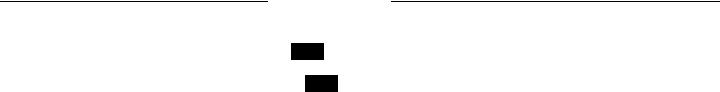
To install batteries in the remote control:
1.Slide the battery compartment cover in the direction of the arrow to remove it.
2.Install two AA batteries with the correct polarity.
3.Replace the cover.
3.1
Remote Control
1. |
2. |
3. |
• Make sure that the battery polarities are correct when installing the batteries. |
Notes on Batteries |
•Do not mix an old battery with a new one or different types of batteries.
•If you will not use the remote control for a long time, remove the batteries to avoid damage from battery leakage.
• In most situations, you can simply point the remote control at the screen which will |
Notes on Remote Control |
reflect the IR signal from the remote back toward the IR receiver on the projector. In |
Operation |
some cases, however, ambient conditions may prevent this. If so, point the remote |
|
control at the projector and try again. |
|
•If the effective range of the remote control decreases, or it stops working, replace the batteries with new ones.
•The remote control may fail to operate if the infrared remote sensor is exposed to bright sunlight or fluorescent lighting.
Runco LS-3/LS-5 Installation/Operation Manual |
13 |
Installation
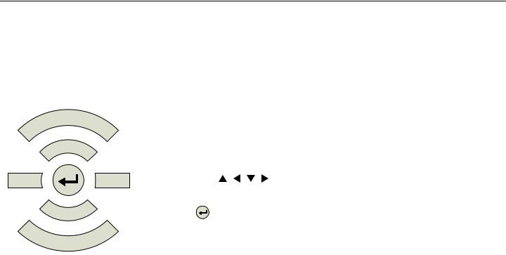
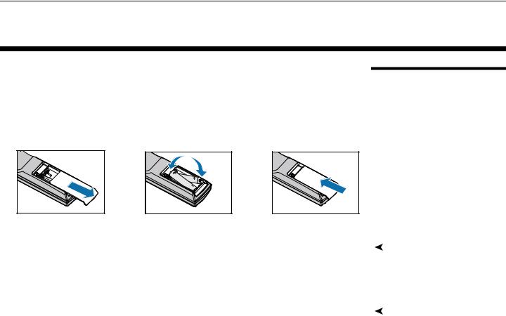
•The projector’s front IR receiver has a range of approximately 40 feet (12.19 meters); the top IR receiver has a range of approximately 20 feet (6.10 meters). Figure 3-1 shows the reception angles of the front and top IR receivers.
Figure 3-1. IR Reception Angles
14 |
Runco LS-3/LS-5 Installation/Operation Manual |
 Loading...