


RX1501
Table of contents
 Loading...
RuggedBackbone™
RX1501
Hardware Installation Guide
Revision 104 - October 14, 2011
www.RuggedCom.com

RuggedBackbone™ RX1501
RuggedBackbone™ RX1501: Hardware Installation Guide
Copyright © 2011 RuggedCom Inc.
All Rights Reserved
Dissemination or reproduction of this document, or evaluation and communication of its contents, is not authorized except where expressly
permitted. Violations are liable for damages. All rights are reserved, particularly for the purposes of patent application or trademark registration.
This document contains proprietary information, which is protected by copyright. All rights are reserved. No part of this document may be
photocopied, reproduced or translated to another language without the prior written consent of RuggedCom Inc.
Disclaimer Of Liability
We have checked the contents of this manual against the hardware and software described. However, deviations from the description cannot
be completely ruled out.
RuggedCom shall not be liable for any errors or omissions contained herein or for consequential damages in connection with the furnishing,
performance, or use of this material.
The information given in this document is reviewed regularly and any necessary corrections will be included in subsequent editions. We appreciate
any suggested improvements. We reserve the right to make technical improvements without notice.
Registered Trademarks
ROX™, RuggedRated™ and eRSTP™ are trademarks of RuggedCom Inc. RuggedRouter® is a registered trademark of RuggedCom Inc.
RuggedBackbone™ is a trademark of RuggedCom Inc. Other designations in this manual might be trademarks whose use by third parties for
their own purposes would infringe the rights of the owner.
Linux® is the registered trademark of Linus Torvalds in the U.S. and other countries.
The registered trademark Linux® is used pursuant to a sublicense from LMI, the exclusive licensee of Linus Torvalds, owner of the mark on
a world-wide basis.
Warranty
Five (5) years from date of purchase, return to factory. For warranty details, visit www.RuggedCom.com or contact your customer service
representative.
Contacting RuggedCom
Corporate Headquarters US Headquarters Europe Headquarters
RuggedCom Inc.
300 Applewood Crescent,
Concord, Ontario
Canada, L4K 5C7
Tel: +1 905 856 5288
Fax: +1 905 856 1995
Toll-free: 1 888 264 0006
Technical Support
Toll Free (North America): 1 866 922 7975
International: +1 905 856 5288
Email: Support@RuggedCom.com
Web: www.RuggedCom.com
RuggedCom
1930 Harrison Street, Suite 209
Hollywood, Florida
USA, 33020
Tel: +1 954 922 7938 ext.103
Fax: +1 954 922 7984
Toll-free: 1 888 264 0006
Email: RuggedSales@RuggedCom.com
RuggedCom
Unit 41, Aztec Centre,
Aztec West, Almondsbury, Bristol
United Kingdom BS32 4TD
Tel: +44 1454 203 404
Fax: +44 1454 203 403

RuggedBackbone™ RX1501
Table of Contents
FCC Statement And Cautions ................................................................................................... 8
1. Product Overview ................................................................................................................... 9
1.1. Functional Overview .................................................................................................... 9
1.2. Feature Highlights ....................................................................................................... 9
2. RuggedBackbone™ Modules .............................................................................................. 12
2.1. Front Panel ............................................................................................................... 13
2.1.1. Module Status LEDs ...................................................................................... 13
2.2. Line Modules (LM) .................................................................................................... 14
2.2.1. Ethernet - Copper ........................................................................................... 14
2.2.2. Ethernet - Fiber .............................................................................................. 14
2.2.3. SFP Modular .................................................................................................. 15
2.2.4. WAN ............................................................................................................... 15
2.2.5. Serial .............................................................................................................. 15
2.2.6. Cellular Modem .............................................................................................. 15
2.2.7. DDS - Digital Data Services ........................................................................... 16
2.2.8. APE - Appplication Processing Engine .......................................................... 16
2.3. Power Supply ............................................................................................................ 17
3. Installation ............................................................................................................................ 18
3.1. Rack Mounting .......................................................................................................... 18
3.1.1. Rack Mounting Dimensions ............................................................................ 18
3.1.2. Panel and DIN Rail Mounting ......................................................................... 20
3.1.3. Panel and DIN Rail Mounting Dimensions ..................................................... 21
3.2. Power Supply Wiring and Grounding ........................................................................ 22
3.2.1. Connectors for HI and HIP Power Modules ................................................... 22
3.2.2. Connectors for 24, 24P, 48, and 48P Power Modules ................................... 22
3.2.3. Chassis Ground Connection .......................................................................... 23
3.2.4. AC Power Supply Wiring Example ................................................................. 23
3.2.5. DC Power Supply Wiring Example ............................................................... 24
3.3. Critical Alarm Wiring ................................................................................................. 24
3.4. Serial Console Port ................................................................................................... 25
3.5. WAN Ports: RJ45 ...................................................................................................... 25
3.6. WAN Ports: BNC ...................................................................................................... 26
3.7. Copper Ethernet Ports .............................................................................................. 26
3.7.1. RJ45 Twisted-Pair Copper Ports .................................................................... 26
3.7.2. Gigabit Ethernet 1000Base-TX Cabling Recommendations ........................... 26
3.7.3. Transient Suppression .................................................................................... 27
3.8. Serial Ports: RJ45 ..................................................................................................... 28
3.9. DDS Ports: RJ45 ...................................................................................................... 28
3.10. DDS Rx and Tx LED Indications ............................................................................ 29
3.11. SFP Optics – Installation, removal, and precautions .............................................. 29
3.11.1. Module Insertion – SFP ............................................................................... 30
3.11.2. SFP Module Removal .................................................................................. 30
3.12. Fiber Ethernet Ports ................................................................................................ 31
3.13. Cellular Modems ..................................................................................................... 32
3.13.1. GSM, EDGE, HSPA+ Cellular Modem Card ................................................ 33
3.13.2. Installing SIM Cards for GSM, EDGE, HSPA+ Cellular Modems .................. 33
RuggedCom® RuggedBackbone™ 3 RX1501 Installation Guide Rev 104

RuggedBackbone™ RX1501
3.14. APE: Application Processing Engine ...................................................................... 35
3.14.1. APE Overview .............................................................................................. 35
3.14.2. Supported Operating Systems ..................................................................... 35
3.14.3. Secondary Network Interface ....................................................................... 36
3.14.4. Installing an Operating System .................................................................... 37
3.14.5. The APE BIOS ............................................................................................. 38
3.14.6. Resetting the Module ................................................................................... 38
3.14.7. LED Indicators .............................................................................................. 38
3.14.8. FAQs ............................................................................................................ 39
4. Technical Specifications ....................................................................................................... 40
4.1. Power Supply Specifications ..................................................................................... 40
4.2. Critical Alarm Relay Specifications ........................................................................... 40
4.3. Copper Ethernet Port Specifications ......................................................................... 40
4.4. Fiber Ethernet Port Specifications ............................................................................ 41
4.4.1. Fast Ethernet (100Mbps) Optical Specifications ............................................. 41
4.4.2. Gigabit Ethernet (1Gbps) Optical Specifications ............................................ 42
4.5. Operating Environment ............................................................................................. 42
4.6. Mechanical Specifications ......................................................................................... 42
5. EMI And Environmental Type Tests .................................................................................... 43
6. Agency Approvals ................................................................................................................ 45
7. Warranty ............................................................................................................................... 46
RuggedCom® RuggedBackbone™ 4 RX1501 Installation Guide Rev 104

RuggedBackbone™ RX1501
List of Figures
2.1. RX1501 Chassis Slot Assignment .................................................................................... 12
2.2. Front View - RX1501 ........................................................................................................ 13
2.3. CG01: 2 × 10/100/1000TX RJ45 ...................................................................................... 14
2.4. 6TX01: 6 × 10/100/1000TX RJ45 ..................................................................................... 14
2.5. FX**/FG**: 2 × 100FX/1000SX/1000LX LC ...................................................................... 14
2.6. 4FX**: 4 × 100FC LC ....................................................................................................... 14
2.7. FX03: 2 × 100 FX MTRJ .................................................................................................. 14
2.8. 4FX03: 4 × 100FX MTRJ ................................................................................................. 14
2.9. FX**: 2 × 100FX SC ......................................................................................................... 14
2.10. FX**: 2 × 100FX ST ....................................................................................................... 14
2.11. 10FL: 3 × 10FL ST ......................................................................................................... 14
2.12. FG5*: 2 × 1000LX/1000SX SFP ..................................................................................... 15
2.13. FX5*: 4 × 100FX/100LX/100SX SFP .............................................................................. 15
2.14. 6FX50: 6 × 100FX SFP .................................................................................................. 15
2.15. TC1: 1 × T1/E1 RJ45 ..................................................................................................... 15
2.16. E01: 1 × E1 BNC ........................................................................................................... 15
2.17. TC2: 2 × T1/E1 RJ45 ..................................................................................................... 15
2.18. E02: 2 × E1 BNC ........................................................................................................... 15
2.19. TC4: 4 × T1/E1 RJ45 ..................................................................................................... 15
2.20. 6S01: 6 × Serial RJ45 .................................................................................................... 15
2.21. W11, W21, W32 Cellular Modem ................................................................................... 15
2.22. W12, W22 Cellular Modem ............................................................................................. 15
2.23. D02: 1 × DDS RJ45 ....................................................................................................... 16
2.24. APE 1402 ........................................................................................................................ 16
2.25. Screw terminal block power module: terminal cover in place (HI module shown) ........... 17
2.26. Screw terminal block power module: terminal cover removed (HI module shown) .......... 17
2.27. Pluggable terminal block power module (HIP module shown) ........................................ 17
3.1. Side View of Mounting Brackets ....................................................................................... 18
3.2. RX1501Rack Mounting Dimensions – Front View ............................................................ 18
3.3. RX1501Rack Mounting Dimensions – Top View .............................................................. 19
3.4. RX1501Rack Mounting Dimensions – Rear View ............................................................. 19
3.5. Installing Panel and DIN Rail Mounting Brackets ............................................................. 20
3.6. DIN Rail Mounting ............................................................................................................ 20
3.7. Panel and DIN Rail Mounting Dimensions ....................................................................... 21
3.8. Screw Terminal Power Connector for HI Power Module .................................................. 22
3.9. Pluggable Phoenix Power Connector for HIP Power Module ........................................... 22
3.10. Screw Terminal Power Connector for 24 and 48 Power Modules .................................. 22
3.11. Pluggable Phoenix Power Connector for 24P and 48P Power Modules ......................... 22
3.12. Chassis Ground Connection ........................................................................................... 23
3.13. Wiring for Single AC Power Supply (HIP module shown) ............................................... 23
3.14. Wiring for Single DC Power Supply (24P or 48P module shown) ................................... 24
3.15. Critical Alarm Relay Connector ....................................................................................... 24
3.16. DB9 Serial Console Port ................................................................................................. 25
3.17. RJ45 T1/E1 Pin Configuration ........................................................................................ 25
3.18. RJ45 T1/E1 Pin Configuration ........................................................................................ 26
3.19. RJ45 Ethernet Pin Configuration .................................................................................... 26
RuggedCom® RuggedBackbone™ 5 RX1501 Installation Guide Rev 104

RuggedBackbone™ RX1501
3.20. RJ45 Serial Pin Configuration ......................................................................................... 28
3.21. RJ45 DDS Pin Configuration .......................................................................................... 28
3.22. DDS Module Rx and Tx LED Indicators ......................................................................... 29
3.23. SFP module orientation .................................................................................................. 30
3.24. SFP module insertion ..................................................................................................... 30
3.25. SFP module removal ...................................................................................................... 31
3.26. LC .................................................................................................................................... 31
3.27. MTRJ ............................................................................................................................... 31
3.28. SC ................................................................................................................................... 31
3.29. ST .................................................................................................................................... 31
3.30. Single Port Cellular Modem: Antenna Connections ........................................................ 32
3.31. Dual Port Cellular Modem: Antenna Connections .......................................................... 32
3.32. Cellular Modem Module Assembly: W11 and W32 Single Antenna Modules .................. 33
3.33. Cellular Modem Module Assembly: W12 Dual Antenna Modules ................................... 33
3.34. APE Faceplate and Ports ............................................................................................... 35
3.35. APE Chassis Network Connection .................................................................................. 36
RuggedCom® RuggedBackbone™ 6 RX1501 Installation Guide Rev 104

RuggedBackbone™ RX1501
List of Tables
2.1. Module Status LED Indications ......................................................................................... 13
3.1. DB9 Serial Console Pinout ............................................................................................... 25
3.2. RJ45 T1/E1 Pin Assignment ............................................................................................. 25
3.3. RJ45 Ethernet Pin Assignment ......................................................................................... 26
3.4. Cabling Categories and 1000Base-TX Compliance .......................................................... 27
3.5. RJ45 RS232/RS485/RS422 Serial Pin Assignment .......................................................... 28
3.6. RJ45 DDS Pin Assignment ............................................................................................... 28
3.7. DDS Rx LED Indications .................................................................................................. 29
3.8. DDS Tx LED Indications ................................................................................................... 29
3.9. Available Fiber Connector Types ...................................................................................... 31
3.10. Cellular Modem Modules ................................................................................................ 32
3.11. HSPA Antenna Requirements ........................................................................................ 33
3.12. APE Specifications .......................................................................................................... 35
3.13. APE Module LED Indicators ........................................................................................... 38
4.1. Power Supply Specifications ............................................................................................. 40
4.2. Form C Contact Relay Specifications ............................................................................... 40
4.3. Copper Ethernet Port Specifications ................................................................................. 40
4.4. Fast Ethernet (100Mbps) Optical Specifications ............................................................... 41
4.5. SFP Fast Ethernet Transceivers ....................................................................................... 41
4.6. Fixed Gigabit Transceivers ............................................................................................... 42
4.7. SFP Gigabit Transceivers ................................................................................................. 42
4.8. Operating Environment ..................................................................................................... 42
4.9. Mechanical Specifications ................................................................................................. 42
5.1. IEC 61850-3 EMI Type Tests ........................................................................................... 43
5.2. IEEE 1613 (C37.90.x) EMI Immunity Type Tests ............................................................. 44
5.3. Environmental Type Tests ................................................................................................ 44
6.1. Agency Approvals ............................................................................................................. 45
RuggedCom® RuggedBackbone™ 7 RX1501 Installation Guide Rev 104
FCC Statement And Cautions
FCC Statement And Cautions
Federal Communications Commission Radio Frequency Interference
Statement
This equipment has been tested and found to comply with the limits for a Class A digital device
pursuant to Part 15 of the FCC Rules. These limits are designed to provide reasonable protection
against harmful interference when the equipment is operated in a commercial environment. This
equipment generates, uses and can radiate radio frequency energy and, if not installed and used in
accordance with the instruction manual, may cause harmful interference to radio communications.
Operation of this equipment in a residential area is likely to cause harmful interference in which
case the user will be required to correct the interference at his own expense.
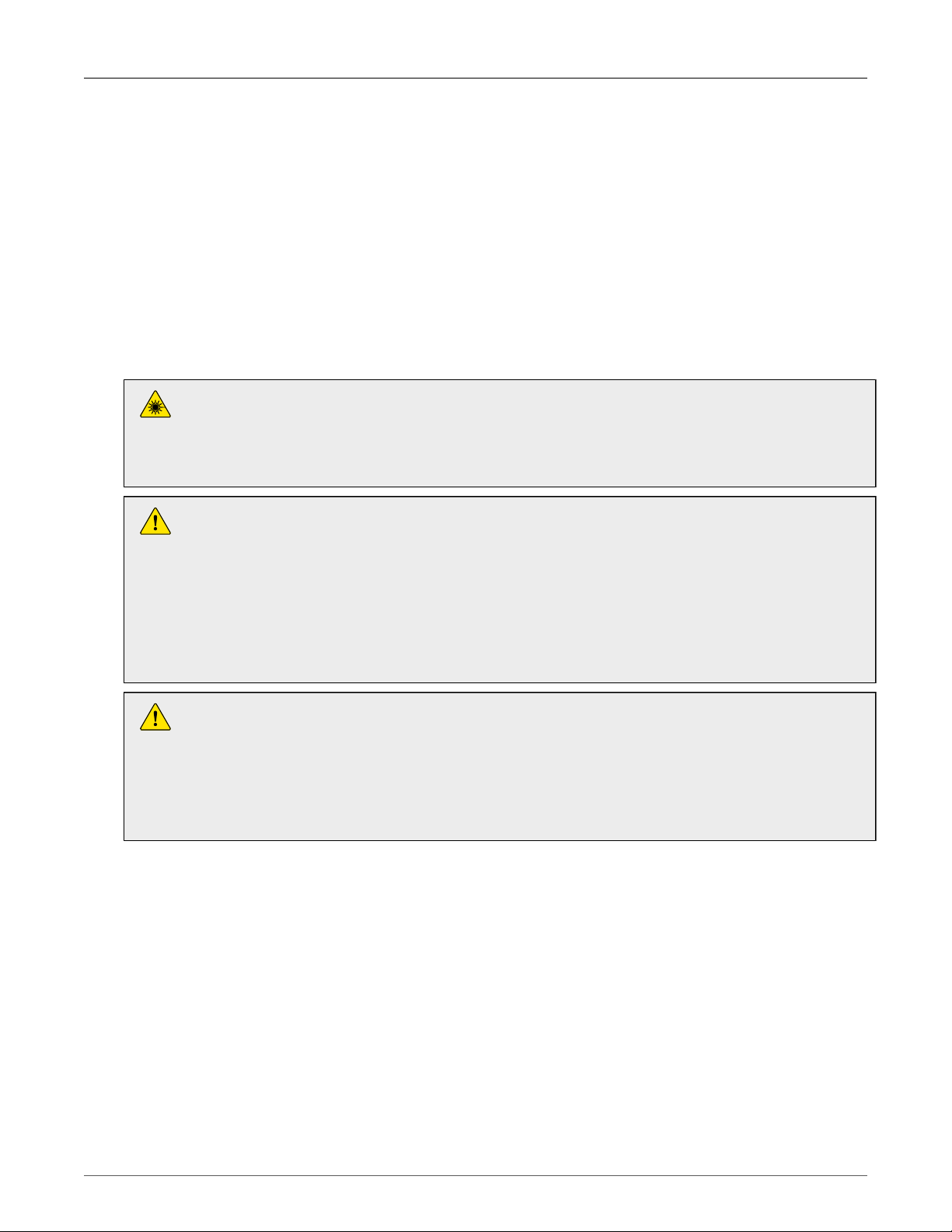
Caution: LASER
This product contains a LASER system and is classified as a CLASS 1 LASER
PRODUCT. Use of controls or adjustments or performance of procedures other than
those specified herein may result in hazardous radiation exposure.
Caution: Service
This product contains no user-serviceable parts. Attempted service by unauthorized
personnel shall render all warranties null and void.
Changes or modifications not expressly approved by RuggedCom Inc. could invalidate
specifications, test results, and agency approvals, and void the user’s authority to
operate the equipment.
Should this device require service, refer to Chapter 7, Warranty in this guide.
Caution: Physical Access
This product should be installed in a restricted access location where access can only
be gained by service personnel or users who have been instructed about the reasons
for the restrictions applied to the location and about any precautions that shall be taken;
and access is through the use of a tool or lock and key, or other means of security,
and is controlled by the authority responsible for the location.
RuggedCom® RuggedBackbone™ 8 RX1501 Installation Guide Rev 104

1. Product Overview
1. Product Overview
1.1. Functional Overview
The RuggedBackbone™ RX1501 is a cost-efficient, rugged layer 3 switch and router. The
RX1501’s modular and field replaceable platform allows you to select WAN, serial, and Ethernet
options, making it ideally suited for electric power utilities, the industrial plant floor, and traffic
control systems.
The RX1501 is designed to the RuggedRated™ specification, providing a high level of immunity to
electromagnetic interference (EMI) and heavy electrical surges typical of the harsh environments
found in many industrial applications. An operating temperature range of -40°C to +85°C (-40°F
to +185°F) allows the RX1501 to be placed in almost any location.
1.2. Feature Highlights
Cyber Security Features
• Multi-level passwords
• SSH/SSL encryption
• Enable/disable ports, MAC-based port security
• Port-based network access control (802.1x)
• VLAN (802.1Q) to segregate and secure network traffic
• RADIUS centralized password management
• SNMPv3 encrypted authentication and access security
RuggedRated™ for Reliability in Harsh Environments
• Immunity to EMI and high voltage electrical transients:
• Zero-Packet-Loss Technology
• Meets IEEE 1613 (electric utility substations)
• Exceeds IEC 61850-3 (electric utility substations)
• Exceeds IEC 61800-3 (variable speed drive systems)
• Exceeds IEC 61000-6-2 (generic industrial environment)
• -40°C to +85°C operating temperature (no fans)
• Optional conformal coated printed circuit boards
• Failsafe Output Relay: For critical failure or error alarming
Physical Ports
• Field replaceable line modules
• Up to 36 ports 100FX
• Up to 36 ports 10/100TX
• Up to 8 ports Gigabit Ethernet
RuggedCom® RuggedBackbone™ 9 RX1501 Installation Guide Rev 104

1. Product Overview
WAN Port Options
• Up to 4 T1/E1 ports via RJ45 connectors (channelized/unchannelized)
• Up to 2 E1 ports via BNC connectors (channelized/unchannelized)
• Cellular/DDS
Serial Ports
• Fully compliant EIA/TIA RS485, RS422, RS232 serial ports (software selectable) with RJ45
connectors
• Raw socket mode support allows conversion of any serial protocol
Protocols
WAN
•
• Frame Relay RFC 1490 or RFC 1294
• PPP RFC 1661, 1332, 1321, 1334, PAP, CHAP Authentication
• Multilink PPP RFC 1990
• GOOSE messaging support
IP
•
• Routing: OSPF, BGP, RIPv1, RIPv2
• VRRP Agent
• Traffic control, NTP Server, IP Multicast Routing
• DHCP Agent (Option 82 Capable)
Frame Relay Support
• ISO and ITU compliant, network certified.
• ANSI T1.617 Annex D, Q.933 or LMI Local Signaling
Management Tools
• Web-based, SSH, CLI management interfaces
• SNMP v1, v2, and v3
• Remote Syslog
• Rich set of diagnostics with logging and alarms
• Loopback diagnostic tests
• Raw and interpreted real-time line traces
RuggedCom® RuggedBackbone™ 10 RX1501 Installation Guide Rev 104

1. Product Overview
Universal Power Supply Options
• Single, removable power supply module
• Single power supply
• Fully integrated power supply (no external adaptor)
• Input voltage ranges: 10-36VDC, 36-72VDC, 88-300VDC, 85-264VAC
• TUV/UL 60950 safety approved to 85°C
Warranty
• 5 Year Warranty
RuggedCom® RuggedBackbone™ 11 RX1501 Installation Guide Rev 104

2. RuggedBackbone™ Modules
2. RuggedBackbone™ Modules
The RX1501 chassis provides seven module slots . Each slot accommodates a particular type
of RuggedCom module. Figure 2.1, “RX1501 Chassis Slot Assignment” shows the module slots
on the RX1501.
Figure 2.1. RX1501 Chassis Slot Assignment
The RX1501 chassis supports the following modules:
LM1 through LM6
The RX1501 chassis supports up to six line module (LM) cards. For more information on line
modules, see Section 2.2, “Line Modules (LM)”.
All modules are built to the RuggedRated™ specifications of the RuggedBackbone™ RX1501.
Each module type is described in the following sections.
To install a module into the RuggedBackbone™ chassis, align the module guide ribs
with the channels on the chassis. Push the module in as far as it will go, being sure to
push through the resistance provided by the grounding springs. When properly seated,
the module flange will rest on the main chassis frame. Tighten the thumbscrews using
finger strength only.
RuggedCom® RuggedBackbone™ 12 RX1501 Installation Guide Rev 104
2. RuggedBackbone™ Modules
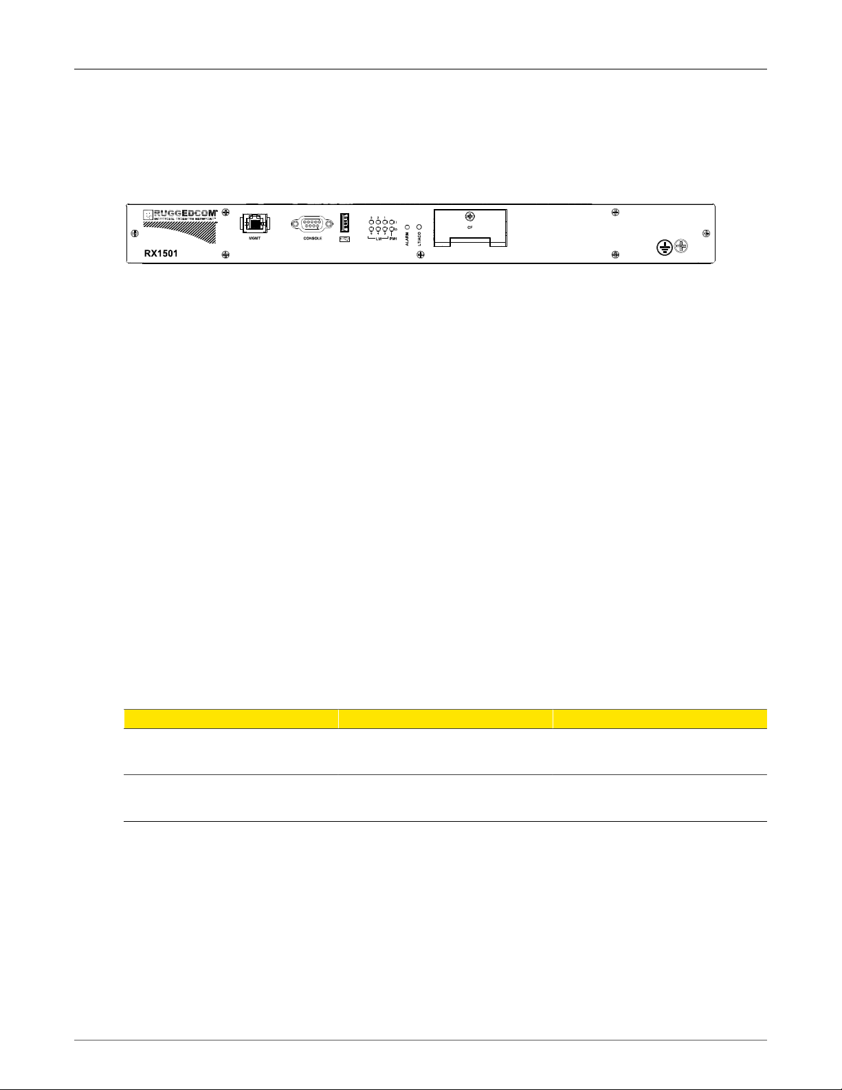
2.1. Front Panel
The RX1501 Front Panel is equipped with an RS232 serial console port for initial management
functions, and a locally connected 10/100Base-T Ethernet port for system management out of
band from the switch fabric.
Figure 2.2. Front View - RX1501
Other Front Panel features include:
• Utility USB port.
• Power module indicator LED.
• Line module indicator LEDs.
• Alarm Indicator LED, which indicates system alarm status.
• Lamp Test / Alarm Cutoff (LT/ACO) button.
• Removable 1GB Compact Flash (CF) card, which contains active and fallback installations of
the ROX™ operating system, along with the configuration database and other system data.
• Chassis ground connection.
For more information on connecting to the ports on the front panel, see the following topics:
• Serial Console: Section 3.4, “Serial Console Port”
• Management Ethernet Interface: Section 3.7, “Copper Ethernet Ports”
• Critical Alarm (Failsafe) Relay Interface: Section 3.3, “Critical Alarm Wiring”
2.1.1. Module Status LEDs
The front panel module status LEDs provide the following information:
LED Purpose Description
PM1 Indicates power supply status.
LM 1 through 6 Indicates the line module status.
Table 2.1. Module Status LED Indications
I = Power supply is receiving input voltage.
O = Power supply is providing
output voltage to the RX1501.
Green = OK
Orange = Warning alert
Red = Configuration error
RuggedCom® RuggedBackbone™ 13 RX1501 Installation Guide Rev 104
2. RuggedBackbone™ Modules
2.2. Line Modules (LM)
The RuggedBackbone™ RX1501 supports six line modules in slots LM1 through LM6 . Several
types of line modules may be ordered, depending on the type, speed, and number of Ethernet
ports required.
The following illustrations show the typical port configurations and connectors available for
RX1501 line modules. For complete information on the available line modules, refer to the
RuggedBackbone™ RX1501 data sheet.
Only one T1/E1 module may be used per router.
On the RX1501, 2-port modules can only be inserted in LM1 and LM2.
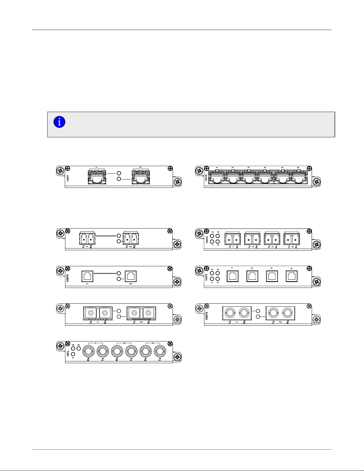
2.2.1. Ethernet - Copper
Figure 2.3. CG01: 2 × 10/100/1000TX RJ45 Figure 2.4. 6TX01: 6 × 10/100/1000TX RJ45
2.2.2. Ethernet - Fiber
Figure 2.5. FX**/FG**: 2 × 100FX/1000SX/1000LX LC Figure 2.6. 4FX**: 4 × 100FC LC
Figure 2.7. FX03: 2 × 100 FX MTRJ
Figure 2.9. FX**: 2 × 100FX SC
Figure 2.11. 10FL: 3 × 10FL ST
Figure 2.8. 4FX03: 4 × 100FX MTRJ
Figure 2.10. FX**: 2 × 100FX ST
RuggedCom® RuggedBackbone™ 14 RX1501 Installation Guide Rev 104
Loading...