


USER'S MANUAL
For the USA
FEDERAL COMMUNICATIONS COMMISSION RADIO FREQUENCY INTERFERENCE STATEMENT
This equipment has been tested and found to comply with the limits for a Class B digital device, pursuant to Part 15 of the FCC Rules.
These limits are designed to provide reasonable protection against harmful interference in a residential installation. This equipment generates, uses, and can radiate radio frequency energy and, if not installed and used in accordance
with the instructions, may cause harmful interference to radio communications.
However, there is no guarantee that interference will not occur in a particular installation.
If this equipment does cause harmful interference to radio or television reception, which can be determined by turning the equipment off and on, the user is encouraged to try to correct the interference by one or more of the following measures:
-Reorient or relocate the receiving antenna.
-Increase the separation between the equipment and receiver.
-Connect the equipment into an outlet on a circuit different from that to which the receiver is connected.
-Consult the dealer or an experienced radio/TV technician for help.
Unauthorized changes or modification to this system can void the users authority to operate this equipment.
The I/O cables between this equipment and the computing device must be shielded.
NOTICE
Grounding Instructions
Do not modify the plug provided - if it will not fit the outlet, have the proper outlet installed by a qualified electrician.
Check with qualified electrician or service personnel if the grounding instructions are not completely understood, or if in doubt as to whether the tool is properly grounded.
Use only 3-wire extension cords that have 3-prong grounding plugs and 3-pole receptacles that accept the tool’s plug.
Repair or replace damaged or worn out cord immediately.
Operating Instructions
KEEP WORK AREA CLEAN. Cluttered areas and benches invites accidents.
DON’T USE IN DANGEROUS ENVIRONMENT. Don’t use power tools in damp or wet locations, or expose them to rain. Keep work area well lighted.
DISCONNECT TOOLS before servicing; when changing accessories, such as blades, bits, cutters, and like.
REDUCE THE RISK OF UNINTENTIONAL STARTING. Make sure the switch is in off position before plugging in.
USE RECOMMENDED ACCESSORIES. Consult the owner’s manual for recommended accessories. The use of improper accessories may cause risk of injury to persons.
NEVER LEAVE TOOL RUNNING UNATTENDED. TURN POWER OFF. Don’t leave tool until it comes to a complete stop.
For Canada
CLASS B |
NOTICE |
This digital apparatus does not exceed the Class B limits for radio noise emissions set out in the Radio Interference Regulations of the Canadian Department of Communications.
CLASSE B |
AVIS |
Cet appareil numérique ne dépasse pas les limites de la classe B au niveau des émissions de bruits radio - électriques fixés dans le Réglement des signaux parasites par le ministère canadien des Communications.
KEEP HANDS AWAY WHEN CUTTING TOOL IS IN MOTION.
`
REGARDEZ BIEN OU VOUS METTEZ LES MAINS LORSQUE L' OUTIL DE DECOUPE FONCTIONNE.
ROLAND DG CORPORATION |
YEARS OF |
||
MANUFACTURE |
|||
1227 Ohkubo-cho, Hamamatsu-shi, Shizuoka-ken, JAPAN 432 |
|||
1996 |
|||
MODEL NAME |
: See the MODEL given on the rating plate. |
||
RELEVANT DIRECTIVE : EC MACHINERY DIRECTIVE (89/392/EEC) |
|
||
|
|||
|
EC LOW VOLTAGE DIRECTIVE (73/23/EEC) |
|
|
|
EC ELECTROMAGNETIC COMPATIBILITY DIRECTIVE (89/336/EEC) |
||
WARNING
This is a Class A product. In a domestic environment this product may cause radio interference in which case the user may be required to take adequate measures.

Table of Contents
Thank you very much for purchasing the <Color CAMM> Model PNC-5000.
•To ensure correct and safe usage with a full understanding of this product's performance, please be sure to read through this manual completely and store it in a safe location.
•Unauthorized copying or transferal, in whole or in part, of this manual is prohibited.
•The contents of this operation manual and the specifications of this product are subject to change without notice.
•The operation manual and the product have been prepared and tested as much as possible. If you find any misprint or error, please inform us.
Table of Contents
Typographic Conventions .......................................................................................................................... |
2 |
||
|
To Ensure Safe Use ................................................................................................................ |
2 |
|
|
About the Labels Affixed to the Unit ............................................................... |
2 |
|
|
To Ensure Correct Use ............................................................................................................................. |
2 |
|
1 |
Checking Supplied Items ...................................................................................................................... |
3 |
|
2 |
Part Names and Functions ................................................................................................................... |
3 |
|
|
2-1 |
Front View ....................................................................................................................................... |
3 |
|
2-2 |
Rear View ........................................................................................................................................ |
3 |
|
2-3 |
Operation Panel ............................................................................................................................. |
4 |
3 |
Set-up and Connections ....................................................................................................................... |
5 |
|
4 |
What the PNC-5000 Can Do .................................................................................................................. |
5 |
|
5 |
Basic Operation ....................................................................................................................................... |
6 |
|
|
5-1 |
DIP Switch Settings ....................................................................................................................... |
6 |
|
5-2 |
Powering On ................................................................................................................................... |
6 |
|
5-3 |
Installing/Removing a Blade ......................................................................................................... |
7 |
|
5-4 |
Installing a Ribbon Cartridge ........................................................................................................ |
8 |
|
5-5 |
Loading/Removing the Material ................................................................................................... |
9 |
|
5-6 |
Downloading Printing/Cutting Data ............................................................................................. |
9 |
|
5-7 |
Pausing Operations .................................................................................................................... |
10 |
|
5-8 |
Removing and Reloading a Printed Material for Cutting ...................................................... |
10 |
|
5-9 |
Cutting Test to Check Cutter Force ........................................................................................... |
11 |
|
5-10 |
Performing a Self-test ................................................................................................................. |
11 |
|
5-11 |
Powering Off ................................................................................................................................. |
11 |
6 |
Printing and Cutting Samples .......................................................................................................... |
12 |
|
7 |
About the Printing/Cutting Area ....................................................................................................... |
13 |
|
8 |
About the Blade .................................................................................................................................... |
13 |
|
9 |
Care and Maintenance ........................................................................................................................ |
14 |
|
10 |
What to Do If... ...................................................................................................................................... |
14 |
|
11 |
Specifications of PNC-5000 ............................................................................................................... |
17 |
|
Clipart used this manual is from CorelDRAWTM
Copyright © 1995 ROLAND DG CORPORATION
1

Typographic Conventions / To Ensure Safe Use
Typographic
Conventions
This manual uses typographic conventions which are outlined at the right.
 This indicates a point requiring particular care to ensure safe use of the product.
|
|
|
|
|
|
|
|
|
|
|
|
|
|
|
|
|
|
: Failure to heed this message will result in serious injury or death. |
|
|
|
|
|
|
|
|
|
: Failure to heed this message may result in serious injury or death. |
|
|
|
|
|
|
|
|
|
|
|
|
|
|
|
|
|
|
|
: Failure to heed this message may result in minor injury. |
|
|
|
|
|
|
|
|
|
|
|
|
|
|
|
|
|
|
|
|
|
|
|
NOTICE |
|
|
: Indicates important information to prevent machine breakdown or |
|
|||
|
|
|
|
|
|
|
|
malfunction and ensure correct use. |
|
|
|
|
|
|
|
|
|
: Indicates a handy tip or advice regarding use. |
|
|
|
|
|
|
|
|
|||
|
|
|
|
|
|
|
|
|
|
|
|
|
|
|
|
|
|
|
|
 To Ensure Safe Use
Never disassemble or modify this product.
Handle the power cord with care.
Do not step on or damage the power cord, or allow heavy objects to be placed atop it. Failure to heed may result in electrocution
or fire.
Ensure the safety of the area around the platen before switching on the power.
The carriage moves simultaneously when the power is switched on.
ON
When pulling the power cord from an electrical socket, be sure to grip the plug.
Do not allow liquids, metal objects or flammables inside the machine.
Fire or breakdown may result.
Do not install in an |
Handle the blade |
Do not inadvertently |
unstable or high location. |
with care. |
allow the hands, hair, or |
Do not install the machine on |
|
necktie near the carriage |
|
while in operation. |
|
the edge of a table, or it may |
|
|
|
|
|
fall. |
|
|
Do not place hands near the platen while in operation.
 About the Labels
Affixed to the Unit
These labels are affixed to the body of this product.
The following figure describes the location.
Do not allow the hands near
the platen while in operation. 


 Rating plate
To Ensure Correct Use
NOTICE |
NOTICE |
NOTICE |
|
NOTICE |
|
This product is a |
Do not install in an area |
Do not connect to an AC |
When the unit is not in use |
||
precision instrument and |
subject to dust, high |
outlet that supplies other |
for an extended period, |
||
must be handled with |
humidity or poor |
than the specified |
|
detach the electrical plug |
|
care. |
ventilation. |
voltage. |
|
from the AC outlet. |
|
|
|
100 V 117 V 220 V |
3 |
|
|
|
|
|
|
2 |
1 |
|
|
|
|
|
|
|
|
240 V |
240 V |
|
|
|
|
|
|
|
|
2
1 Checking Supplied Items / 2 Part Names and Functions
1 Checking Supplied Items
Check the following to make sure that you received all the items that were shipped along with the unit.
• Power Cord |
: 1 |
• Thermal transfer ribbon cartridge |
: 1 |
• Blade (Carbide) |
: 1 |
• Blade Holder |
: 1 |
• Roller Base |
: 1 |
• Cutter Tool |
: 1 |
• Material for Test Cuts |
: 1 |
• Alignment Tool |
: 1 |
• Head Cleaner |
: 1 |
• Cleaning Sheet for Printing Head |
: 1 |
• Hexagonal Screw Driver |
: 1 |
• User's Manual |
: 1 |
2 Part Names and Functions
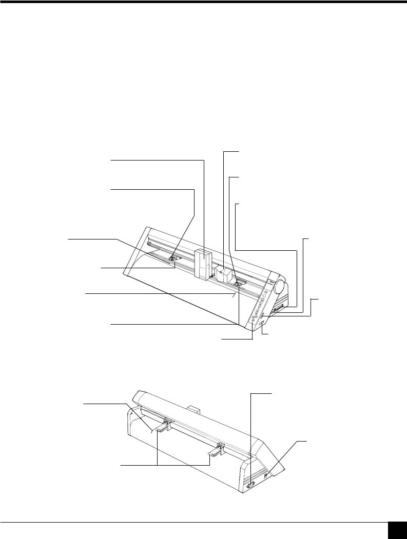
2-1 Front View
Printing Carriage
The ribbon cartridge is mounted here.
Pinch Roller (Left)
Press material against the grit roller. When loading material, place the left roller inside the left edge of the material to correctly track it through the machine.
Cutting Carriage
The blade holder is mounted here.
Pinch Roller (Right)
This presses the material against the grit roller.
Serial (RS-232C) Input Connector
In a serial configuration, connect the serial cable here. This cable carries data to your computer.
Platen
Grit Roller (Left)
Guide Line
Align the material with these lines when loading.
Grit Roller (Right)
Operation Panel
Parallel (Centronics) Input Connector
In a parallel configuration, connect the parallel cable here. This cable carries data to your computer.
DIP Switches
Used to make various settings.
Cutter Force Control Slider
Sets the down force for the cutting tool.
2-2 Rear View
Guide Line
Align the material with these lines when loading.
Sheet Loading Lever
Used to raise or lower the pinch rollers when loading or unloading material.
Power Connector (AC IN)
This connector accepts standard AC power cord.
Power Switch
3
2 Part Names and Functions
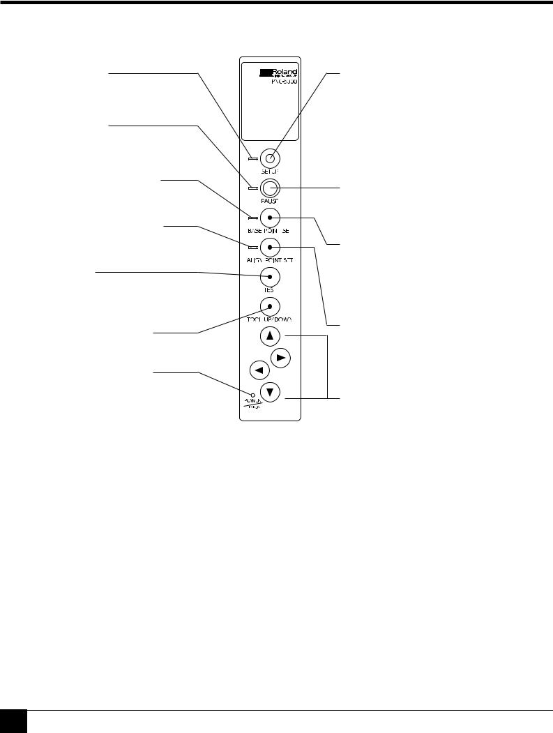
2-3 Operation Panel
SETUP LED
Lights when the SETUP key is pressed. Operations can be performed when lighted.
PAUSE LED
Lights when the PAUSE key is pressed to stop the PNC-5000 temporarily.
BASE POINT SET LED
Lights when the base point is set.
ALIGN POINT SET LED
Lights when the align point is set.
TEST Key
Executes a cutting test to check material characteristics, cut quality, and suitable pressure for the blade.
TOOL UP/DOWN Key
Moves the tool move up or down.
POWER/ERROR LED
Lights when the power is switched on and flashes when an error is generated.
SETUP Key
Pressing this key after loading material detects the position of the pinch rollers and automatically determines the area for printing or cutting. Also, pressing this key after using the PAUSE key to temporarily stop an operation in progress will delete the data that has been sent to the PNC-5000 from the computer. This key must be pressed in order to begin printing or cutting.
PAUSE Key
When pressed once, this key temporarily halts operation in progress. Pressing this key again releases the paused state.
BASE POINT SET Key
When material has been reloaded, pressing this key sets the base point (the crop-mark position at the front-right edge of the material). For more details, see section “5-8 Removing and Reloading Printed Material for Cutting.”
ALIGN POINT SET Key
When material has been reloaded, pressing this key sets the align point (the crop-mark position at the front-left edge of the material). For more details, see section “5-8 Removing and Reloading Printed Material for Cutting.”


 (Cursor Keys)
Pressing the  ,
,  ,
,  , and
, and  keys causes the tool or material to move in the specified direction.
The SETUP LED and POWER/ERROR LED blink simultaneously.
The SETUP LED and POWER/ERROR LED blink simultaneously if material is not loaded correctly. See “5-5 Loading/Removing Material” for an explanation of how to load material.
The PAUSE LED and POWER/ERROR LED blink simultaneously.
The PAUSE LED and POWER/ERROR LED blink simultaneously if no ribbon cartridge is installed, or if the ink ribbon has run out. For more details, see “5-4 Installing a Ribbon Cartridge.”
4
 Loading...