


43-1090
Cat. No. 43-1088/1090
OWNER’S MANUAL
Please read before using this equipment.
900-MHz Cordless Telephone
with Headset Jack
ET-918 White(43-1088)
ET-920 Black(43-1090)
43-1088_90.fm Page 1 Tuesday, August 17, 1999 2:57 PM

2
FEATURES
© 1997 Tandy Corporation.
All Rights Reserv ed .
COM-LOK and RadioShack are registered trademarks used by T a ndy Corporation.
Your RadioShack ET-918/920 900-
MHz Cordless Telephone with Head-
set Jack uses the 900 MHz band which
means less interference, clearer
sound, and greater range than 46/49
MHz cordless telephones.
And, its headset jack m eans you can
connect an optional headset for hands-
free convenience while you use the
phone.
The phone’s other features include:
900 MHz Operation
— provid es long-
er range and less interference than
many other cordless phones.
40 Channels
— automatically selects
a clear channel when you make or an-
swer a call. You can also manually
change channels during a call.
Super CCT Noise-Reduction Cir-
cuitr
y
— provides clear telephone
conversations, giving you sound clarity
comparable to that of a corded phone.
Securit
y
Access-Protection Code
—
automatically prevents other cordless
phone users from using your phone
line while the handset is off the base.
COM-LOK
®
— ensures that other
cordless phone users cannot u se your
phone line when the handset is on the
base.
Redial
— lets you quickly redial the
last number dialed.
10-Number Memor
y
Dialin
g
— lets
you store up to 10 numbers in memory
for easy dialing.
Pa
g
e
— lets you send a paging signal
from the base to the hand set to page
someone or loca te the handset if you
misplace it.
Flash
— sends a n electronic switch-
hook signal for use with special phone
services, such as Call Waiting.
Volume Control
— lets you adjust
the volume you hear through the
handset.
Pro
g
rammable Rin
g
er
— lets you
select from four ringer tone/volume
settings.
Tone/Pulse Dialin
g
— lets you use
your phone with tone or pulse service.
Quick Talk
— lets you make or an-
swer a call by just lifting the handset
from the base.
Hearin
g
-Aid Compatibilit
y
— lets
you use your phone with he aring aids
that have a T (telephone) switch.
This telephone has been tested and
found to comply with all applicable UL
and FCC standards.
43-1088_90.fm Page 2 Tuesday, August 17, 1999 2:57 PM
3
Important Note: Cordless phones
such as this one require AC power to
operate. When the AC power is off,
you cannot dial out or receive incoming
calls using your phone. To be safe, you
should also have a phone that does
not need AC power to ope rate (not a
cordless phone) so you c an still make
and receive calls if there is an AC pow-
er failure.
We recommend you record your
phone’s serial number here. The num-
ber is on the bottom of the base.
Serial Number __________________
This sym bol is in te nd ed to a le rt yo u
to the pr e s en ce of uninsu la ted dan-
gerous voltage within the product’s
enclos u re t h at m ig ht b e of s ufficient
magnitude to constitute a risk of
electric shock. Do not open the
product’s case.
This symbol is intended to inform
you that important operating and
maintenance instructions are in-
cluded in th e l itera ture a ccomp an y-
ing this product.
RISK OF ELECTRIC SHOCK.
DO NOT OPEN.
CAUTION: TO REDUCE THE RISK OF
ELECTRIC SHOCK, DO NOT REMOVE
COVER OR BACK. NO US ER-SERVICE-
ABLE PARTS INSIDE. REFER SERVIC-
ING TO QUALIFIED PERSONNEL.
Warning: To reduce the risk of fire
or shock hazard, do not expose
this product to rain or moisture.
CAUTION
!
!
READ THIS BEFORE
INSTALLATION
Each device that you connect to the
phone line draws power from the
phone line. We refer to this power draw
as the device’s
ringer equivalence
number
, or
REN
. The REN is on the
bottom of the base.
If you are using more than one phone
or other device on the line, add up all
the RENs. If the total is more than five,
your phones might not ring. In rural ar-
eas, a total REN of three might impair
ringer operation. If ringer operation is
impaired, remove a device from the
line.
FCC STATEMENT
This telephone complies with Part 68
of
FCC Rules
. You must, upon re-
quest, provide the FCC Registration
Number and the REN to your phone
company. These numbers are on the
bottom of the base.
Note: You must not connect your
phone to any of the following:
• coin-operated syst e ms
• party-line systems
• most electronic key phone sys-
tems
43-1088_90.fm Page 3 Tuesday, August 17, 1999 2:57 PM

4
CONTENTS
Installation ............................................................................................................ 5
Selecting a Location ........................................................................................ 5
Placing the Base on a Desk Top ............................................................... 5
Mounting the Base on a Wall Plate ........................................................... 6
Mounting the Base Directly on the Wall .................................................... 7
Connecting and Charging the Battery Pack .................................................... 9
Setting the Dialing Mode ............................................................................... 11
Setting the Ringer Tone/Volume .................................................................... 11
Operation ............................................................................................................ 12
Making and Receiving Calls ............................................................. . ............ 12
Selecting the Channel ................................................................................... 12
Setting the Handset Volume .......................................................................... 12
Using REDIAL ............................................................................................... 12
Using FLASH ................................................................................................. 13
Using Tone Services on a Pulse Line ............................................................ 13
Paging ........................................................................................................... 14
Memory Dialing .............................................................................................. 14
Storing a Number in Memory .................................................................. 14
Entering a Pause .................................................................................... 15
Dialing a Memory Number ...................................................................... 15
Chain-Dialing Service Numbers .............................................................. 16
Testing Stored Emergency Numbers ...................................................... 16
Using a Headset ............................................................................. ............... 16
Troubleshootin
g
................................................................................................. 17
Care and Maintenance ....................................................................................... 19
Replacing the Battery Pack ........................................................................... 20
The FCC Wants You to Know ........................................................................ 21
Lightnin g ........................................................................................................ 21
43-1088_90.fm Page 4 Tuesday, August 17, 1999 2:57 PM
5
INSTALLATION
SELECTING A
LOCATION
You can place t he phone’s bas e on a
desk top or table, or mount it on a wall.
Select a location that is:
• near an AC outlet
• near a telephone line jack
• out of the way of normal activities
• away from electrical machinery,
electrical appliances, metal walls
or filing cabinets, wireless inter-
coms, alarms, and room monitors
• away from other cordless phones
The base’s location affects the hand-
set’s range. If you have a choice of
several locations, try each to see
which provides the best performance.
Caution:
The supplied RadioShack
AC adapter was designed specifically
for your ET-918/920. Use only the sup-
plied adapter.
Notes:
• Your telephone connects directly
to a modular telephone line jack. If
your phone line jack is not a mod-
ular jack, you can update the wir-
ing yourself, using jacks and
adapters available at your local
RadioShack store. Or, you can let
the phone company update the
wiring for you.
• The USOC number o f the jack to
be installed is RJ11C (RJ11W if
you want to mount it on a wall
plate).
Placing the Base on a
Desk Top
Follow these steps when you place the
base on a desk, shelf, or table.
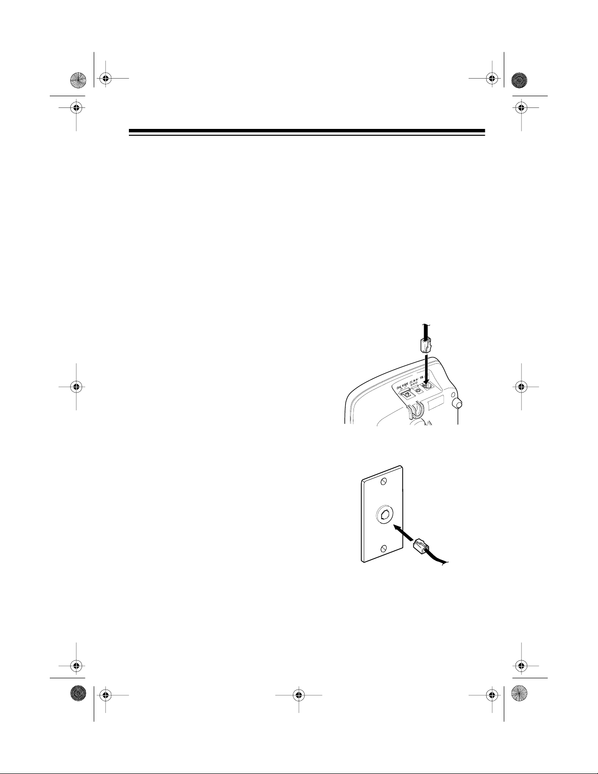
1. Plug one en d of the supp lied long
modular cord into the
TEL LINE
jack on the back of the base.
2. Plug the modular cord’s other end
into a modular phone line jack.
43-1088_90.fm Page 5 Tuesday, August 17, 1999 2:57 PM
6
3. Insert the supplied AC adapter’s
barrel plug into the
DC IN 9V
jack
on the back of the base.
4. Route the adapt er’s cord through
the strain relief slot on the base
(as shown).
5. Plug the adapter into a standard
AC outlet. The POWER indicator
on the base lights.
6. Lift the base’s antenna to a verti-
cal position.
Mounting the Base on a
Wall Plate
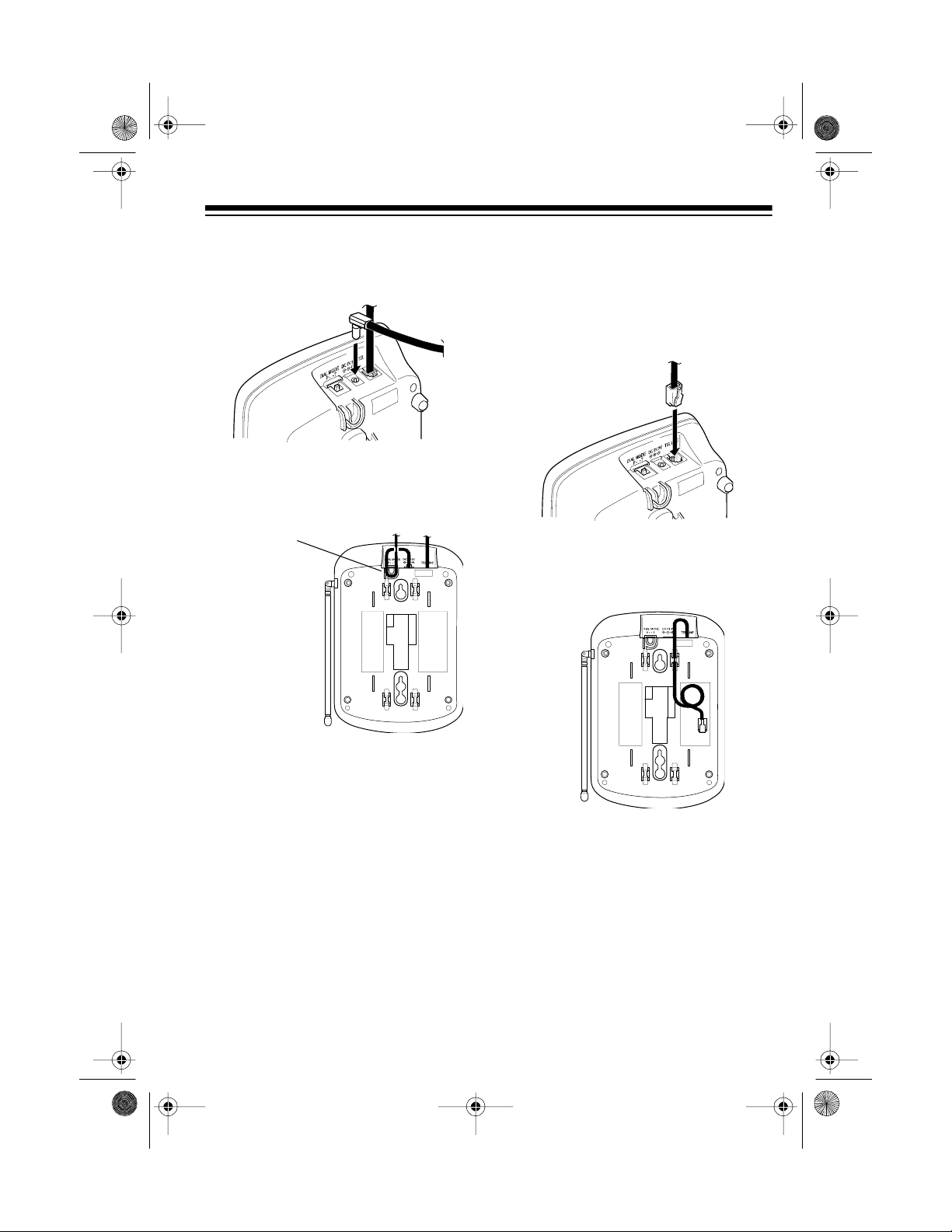
1. Plug one end of the supplied short
modular cord into the
TEL LINE
jack on the back of the base.
2. Route the modular cord through
the right slot on the bottom of the
base.
Strain Relief
Slot
43-1088_90.fm Page 6 Tuesday, August 17, 1999 2:57 PM
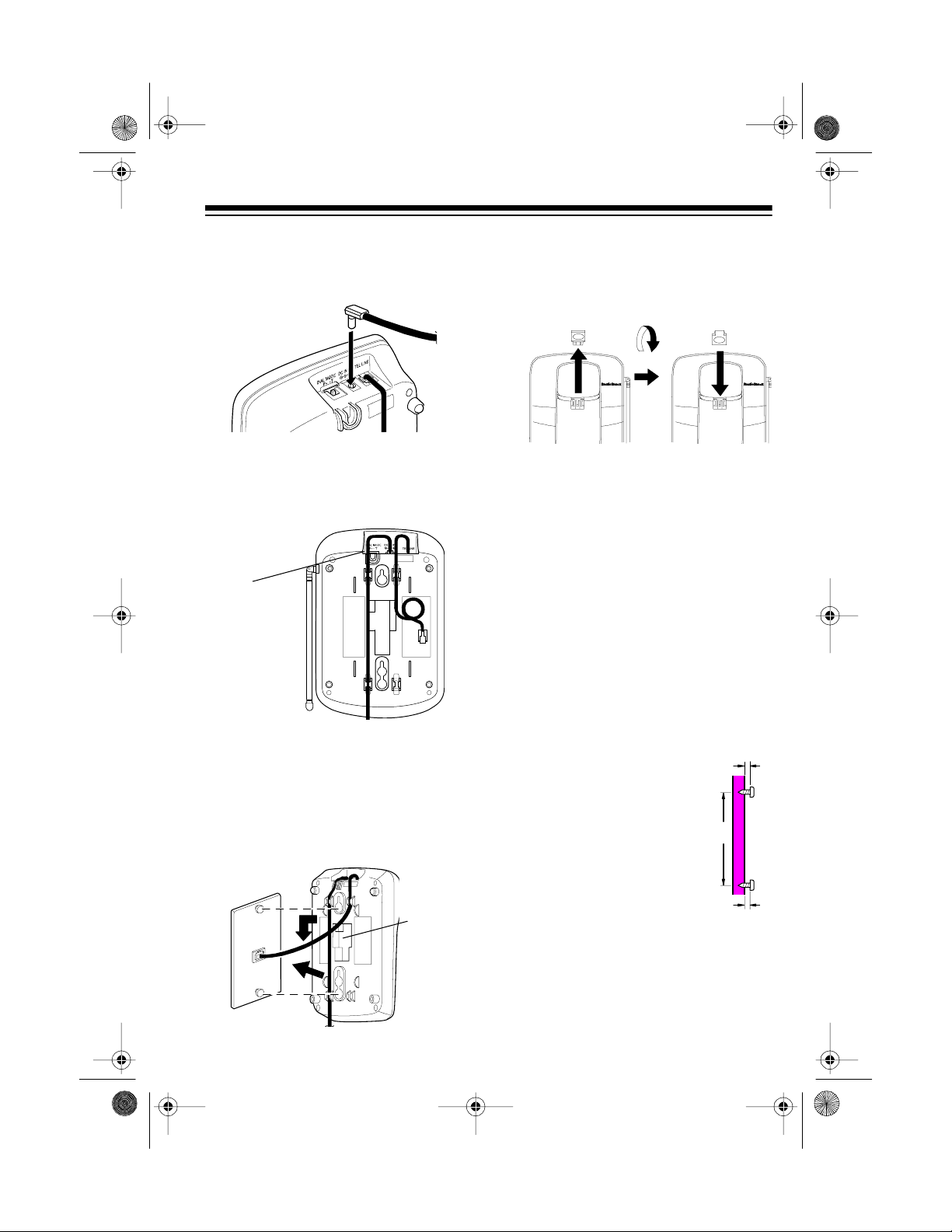
7
3. Insert the supplied AC adapter’s
barrel plug into the
DC IN 9V
jack
on the back of the base.
4. Route the adapt er’s cord through
the left side of the strain relief slot
on top of the base and through the
left slots at the bottom of the base.
5. Plug the short modular cord into
the wall plate jack, press the
excess cord into the slot in the
center of the base, then align the
base’s keyhole slots with t he wall
plate studs and slide the base
downward to secure it.
Strain Relief
Slot
Slot for
Excess
Cord
6. Press and lift out the handset
holder, turn it over and rotate it
180°, then snap it b ack into plac e
so it holds the handset.
7. Plug the adapter into a standard
AC outlet. The POWER indicator
on the base lights.
8. Lift the base’s antenna to a verti-
cal position.
Mounting the Base Directly
on the Wall
For this mounting method, you need
two flat-head wood screws (not sup-
plied) with heads that fit into the key-
hole slots on the bottom of the base.
1. Drill two holes 3
15
/
16
inches apart. Then
thread a screw into
each hole, letting the
heads extend about
3
/
16
inch from the
wall.
3
/
16
3
15
/
16
43-1088_90.fm Page 7 Tuesday, August 17, 1999 2:57 PM

8
2. Plug one end of the supplied long
modular cord into the
TEL LINE
jack on the back of the base.
3. Route the modular cord through
the right slots on the bottom of the
base.
4. Insert the supplied AC adapter’s
barrel plug into the
DC IN 9V
jack
on the back of the base.
5. Route the adapter ’s cord through
the left side of the strain relief slot
on top of the base and through the
left slots on the bottom of the
base.
6. Align the keyhole slots with the
mounting screws and slide the
base downward to secure it.
7. Plug the modular cord into a m od-
ular phone line jack.
Strain Relief
Slot
43-1088_90.fm Page 8 Tuesday, August 17, 1999 2:57 PM
 Loading...